
10
Soldering and Sewing to Complete Your Project
Learning soldering and sewing techniques to complete a project will provide you with a valuable skillset. This chapter teaches you the basics of soldering to help you to make your circuits more durable and permanent. These skills will help you to take your projects to the next level, from a low-fidelity prototype to a high-fidelity prototype, and ready for wearing.
In this chapter, you will try soldering! We will explore the tools and items we should have, learn some ways to improve our soldering practice, and try a few activities so we can learn this skill. After soldering, we will focus on sewing to make wearables. We will try some activities to put these techniques into practice. Once we have a foundation for soldering, we’ll revisit our project from Chapter 9, Designing and Prototyping Your Own Hyper-Body System. This will provide the practical element as we turn it into a wearable system. Now is the time to take this implementation prototype and to consider the look and feel and the role of the prototype.
By the end of this chapter, you will have transformed your breadboard prototype from the previous chapter into a wearable! You’ll also have practiced your soldering and sewing skills and picked up some hints and tips for a better maker practice.
In this chapter, we’re going to cover the following main topics:
- Soldering
- Sewing
- Putting your wearable together
Technical requirements
This chapter is all about learning how to solder and sew your hyper-body wearable from the last chapter. These items are suggested, but we’ll go through how to use them as we work through the chapter. Items can be found on various supplier websites (see https://cpc.farnell.com/, https://www.digikey.co.uk/, https://uk.rs-online.com/web/, https://www.mouser.co.uk/, or https://www.tinkertailor.tech/). You’ll need your prototype from the last chapter and a switch to use as an on/off switch, as well as the following:
- Items for soldering:
- A soldering iron, stand, and lead-free solder
- Brass wire sponge solder iron cleaner and tip tinner
- Wire cutters and tools for soldering
- Resistors of any value and a protoboard/perfboard
- Wires: 22 AWG or 24, an LED, a 220 Ohm resistor, and heat shrink tubing
- Flux, helping hands, a solder mat, and masking tape
- Items for sewing:
- A sewing needle, needle threader, and thread
- Fabric, a hoodie, jumper, sweater, or similar
- Optional items: nail varnish, fabric glue, a glue gun, and glue sticks
Soldering
Soldering is a way to join metal (wires, for example) by adding another metal (fusible alloy) that melts (solders) at a lower temperature than the two metal pieces we want to be joined. The solder is the glue holding it together. The purpose is to form a permanent conductive connection between the two connections. It needs to be a good enough connection to survive a pull test. When we’ve soldered our items, we will try the pull test to be sure our connections hold. Welding melts all the metal items together using higher temperatures, and we won’t be doing that with our soldering process. Solder is a mix of tin, lead, and sometimes flux. We can buy lead-free solder, and this is what I would recommend as lead-based solder is too dangerous, not environmentally friendly, and not worth the risk.
You’ll need skill and dexterity to solder. This challenge is something I thoroughly enjoy doing! Practice using old components or buy resistors that are inexpensive and good for practicing with. Let’s have a look at the different items we can use, or need, to solder.
Items used for soldering
These are some of the items we need for soldering. Figure 10.1 is the base station that I use and take with me everywhere:
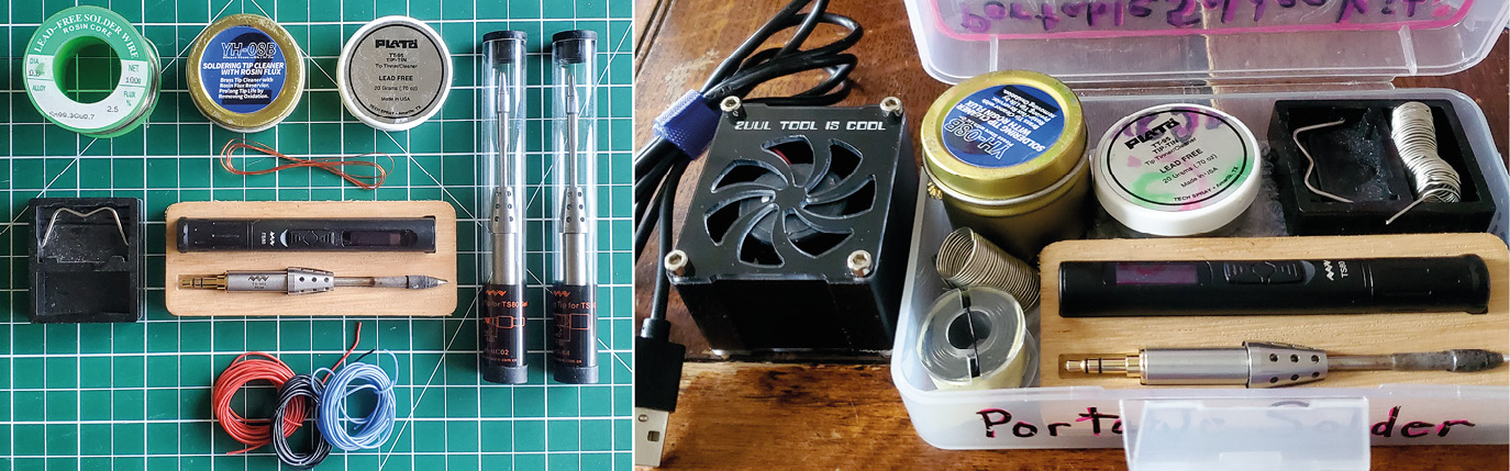
Figure 10.1 – My portable solder station items
On the left are the items: solder, a brass cleaning sponge with tip cleaner, tip cleaner, small 24 AWG silicone wires, my Miniware portable solder iron, and spare tips in different styles. On the right, is everything packed into a portable box. There’s also a mini solder fan that I use that is USB-powered and it pulls the fumes away as I solder. The items in this list will provide you with a foundation of knowledge so you can then research what items you would like to work with. Let’s set up your solder station!
Solder
You’ll often see this sold as 60/40, which means it has a mix of 60 tin and 40 lead. This is called soft solder and melts around 180–190 degrees Celsius. There is lead-free solder that is ecologically responsible, which started appearing when rules banning lead in products started happening. Lead-free has a higher melting point. You’ll also come across flux core solder. This is a spool that has a reducing agent in its center. This flux is released as you solder, and you get a cleaner connection because it improves the flow. Flux is typically made from rosin. When shopping for solder, you might also come across terms such as SAC (Sn-Ag-Cu); this details the constituents in the solder, which can be silver, antimony, bismuth, copper, nickel, or others. SAC solder is a lead-free version that melts really well:
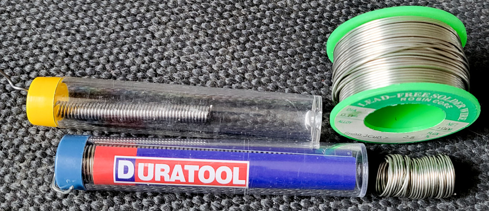
Figure 10.2 – Different types of solder in tubes and on a spool
You can buy solder in large spools, and in different widths (Figure 10.2). A solder with a diameter of 0.75 mm to 1.0 mm is good for the component sizes we are working with for wearables. If your solder is too thick, you’re liable to get a big gloop of it that might bridge the connections. To bridge a connection means it might create a connection between two pins that we don’t want to be connected. It can cause a short, or stop our component from working correctly, and is generally the way to break our components.
You can use your multimeter to test whether you have bridged your solder joins, and we’ll learn how in the upcoming Activity 10.3 – Using a multimeter to check connections. Also, if you buy solder in tubes, don’t throw away your tubes. Buy a spool of solder that you like and then, using a marker such as this sharpie (Figure 10.3), wrap your solder around it. Then, cut it and refill your tube:

Figure 10.3 – Making a refill of solder for solder tubes
I recommend getting 0.75 mm thickness, lead-free solder, in the handy solder tube format. Look out for Antex, Duratool, Draper, and other brand names that are good.
Flux
Flux is a chemical used for soldering (Figure 10.4). You can use it before you solder for preparing the surface of the item we are soldering. It prepares the surface by removing oxides that could prevent a good solder joint from forming. It helps the soldering process and I find it helps the flow and transfer of solder to the items I’m soldering together. Flux comes in different forms, which can be solid, pasty, or liquid. You can get it in tins or pen formats too, which makes it easy to apply straight to the parts you want to solder. I’ve found that soldering with lead-free solder can benefit from using flux to help the solder flow:
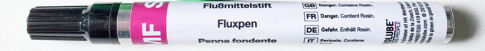
Figure 10.4 – Flux pen
The tin or jars can be good for dipping a wire in to coat it. Some flux varieties will need cleaning off the surfaces, so look for no-clean as a preferred type – though it is still recommended that you wipe your board off after using flux. You can use isopropyl alcohol to clean a circuit board. There is a flux pen made by Chip Quik that is lead-free and it’s a reliable brand. This pen-style flux should last you a long time, depending on how often you solder.
Wires
A wire carries the current to the components in our circuit. There are a few types of wire that we can use that have different purposes. Solid core wire is a single piece of metal, called a strand. These wires are great for breadboards because we can easily bend them to fit into the breadboard holes and because the single wire is thick, it is easy to push through the hole and stays in place:

Figure 10.5 – Multicore (stranded) wire (left) versus solid core in a breadboard
Multicore (stranded) has many wires inside. This makes it easier to flex and bend than solid core wire. If you want to push it into a breadboard, you’ll need to hold all the strands together and twist. This way the strands will stay together before you press them into the breadboard hole. Even then, it can be difficult to push the strands all through, and often a few strands sit on top of the breadboard. Also, after twisting the ends together to hold all the strands, you might want to tin them with solder. Tinning means covering it with a thin layer of solder to give it a light coating. In Figure 10.5, we can see the difference with a stranded wire; there is a chance that it may connect to the wrong area.
If you have moving circuit parts, then a stranded wire is better suited for the job due to its flexibility. The silicone variety of wires is great to work with for wearables. It has a soft super-flexible surface and comes in a variety of colors too. You can usually buy these in small packs with five or six color spools.
Wires are measured in gauges, and the gauge also determines the amount of current that can safely go through it. I’ve mentioned the American Wire Gauge (AWG) of the wires we’ve been using, around 22 AWG (0.644 mm) and 24 AWG (0.511 mm). I would recommend getting a variety of 22 and 24 AWG wire, in both solid core for your breadboarding, and silicone for when you want to solder your circuits and put them into wearables.
Headers
Headers are needed to solder different components. You can find colored headers, though the most common is black. It’s a good idea to get a multipack with varieties to suit different needs depending on your components:
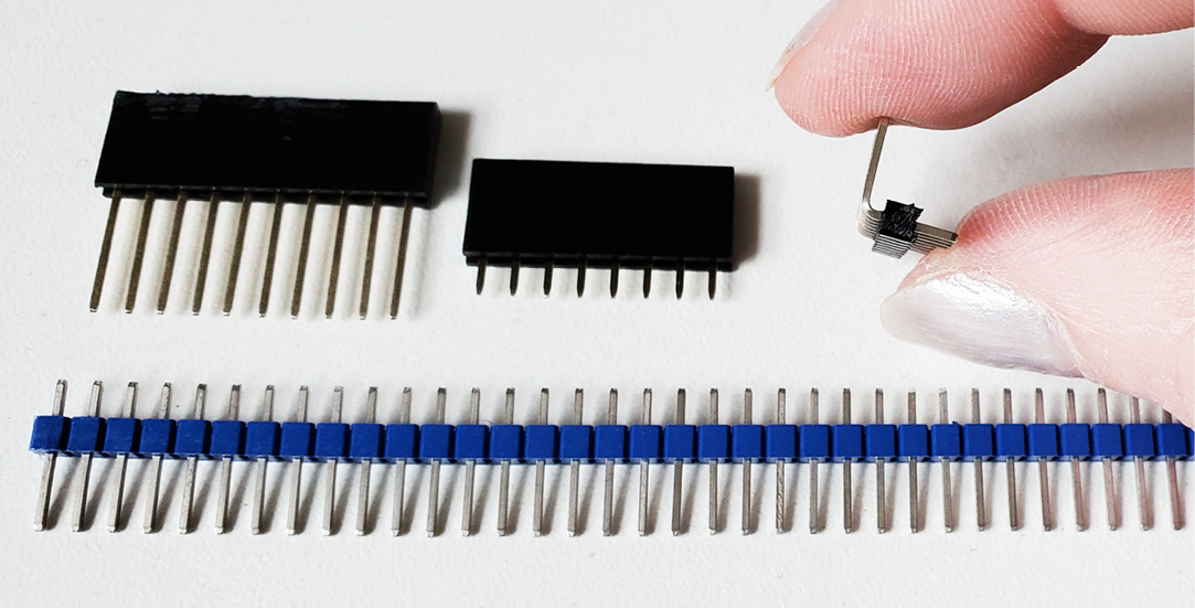
Figure 10.6 – Different headers; I’m holding the right-angle header
Figure 10.6 shows breakaway male headers on the bottom and a stackable header above. Stackable headers are useful when you want to put one board on top of another to save space, provided the pin numbers match up. When buying pin headers, be sure to search for Arduino pin headers or sized at 2.54 mm pitch.
Heat shrink tubing
Heat shrink is a plastic tube that we place over our soldered connection and wires so we can insulate them. The tube is larger than the wires/component. You slide it over the connection and then apply heat. This can be done with a hot air gun. Some people use a lighter, but this can burn and melt it unevenly. Figure 10.7 shows a NeoPixel end that has wires soldered to it, covered with heat shrink, and then heated so you can see the before and after of this process. This will add stability to our soldered wires and be less fragile:
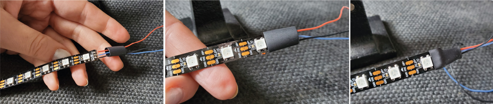
Figure 10.7 – Heat shrink on the end of NeoPixels, covering our soldered wire end
You can buy single and dual wall heat shrink tubing; dual has adhesive inside and it will provide waterproofing when it is shrunk into place. Heat shrink tubing shrinks around the wires but it typically doesn’t shrink in length. I would recommend getting a variety pack to start, with different sizes and colors. I mostly use black and red, and my preference is clear. It can be useful to be able to see the soldered connection just in case it has come apart. We will be looking at using heat shrink in the activities in this chapter.
Removing solder – desoldering braid
If you put too much solder on by accident or need to remove solder to swap a component, you can use solder wick (desoldering braid). Pictured in Figure 10.8 is a selection of the forms that desoldering braid is available as. It’s made from thin copper wire that is braided together:
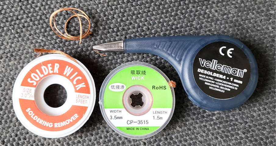
Figure 10.8 – Desoldering braid
If you need to remove some solder, place the braid over the solder you want to remove and then place the solder iron tip on top. The heat will allow the solder to flow from the board to the braid as if the solder is being soaked up. It comes in different wick sizes, and it might be a good idea to grab one thin and one thick. For larger amounts of solder to be removed, you can use a solder pump. These are used by hand and there are also powered versions.
Tools
There are a few tools that will make soldering and component work much easier. For example, to cut wire, you’ll need cutters, and to manipulate components and wire, you’ll need pliers. I use flush side cutters for cutting wire and for cutting the ends of wire after I’ve soldered. This gets right up close against the circuit board and allows for a clean cut. Needle nose pliers are great for getting into small areas and doing small jobs. The pair from Engineer (see Figure 10.9, left) has a rounded tip so you can use these for winding your component legs into circles so you can sew them:
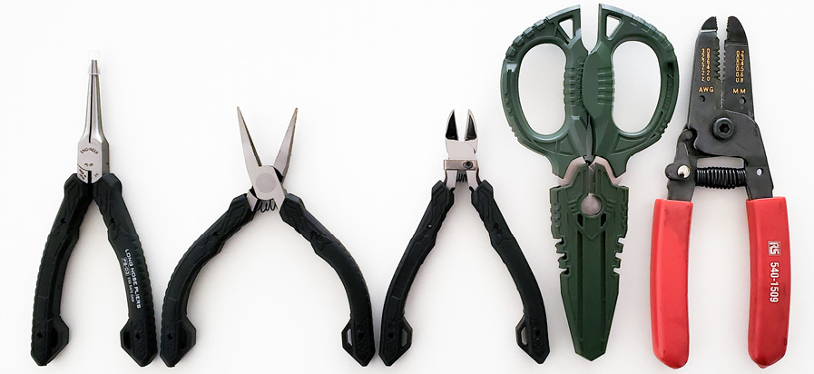
Figure 10.9 – Needle nose, flat nose, flush cutters, scissors, and wire strippers
The flat nose pliers have flat edges so are great for creating square bends in components and I often use them to hold components. I’ve also included Engineer scissors because they are multipurpose and make a great addition to a maker’s toolkit. They have different blade areas and wire cutters between the handles. Also, a pair of wire strippers is a good idea to make stripping wires easier. You can use cutters, but it takes practice, and you won’t want to do that long-term.
For soldering and electronics, try to find a pair of the following:
- Cutters
- Pliers (flat nose and needle nose)
- Wire strippers
I’ll also mention that a multimeter is an essential tool too – but I’m hoping you’ll already have one of those in your toolkit as we’ve been using it throughout the book. Have a look at the start of this chapter for links to where you can purchase these tools; good brands include Engineer, RS Pro Tools, and Weller, and the top of the range is often considered Lindstrom.
Helper tools
You’ll find you need to be ambidextrous to hold your component, wires, solder, iron, and so on, and your hands fill up quickly. Having a stand such as a helping hands stand (shown in Figure 10.10) can make things easier. The one shown has a magnifier so you can see up close too. Some helping hands or multihand holders have lights, larger magnifiers, and more than two clips to hold multiple parts:
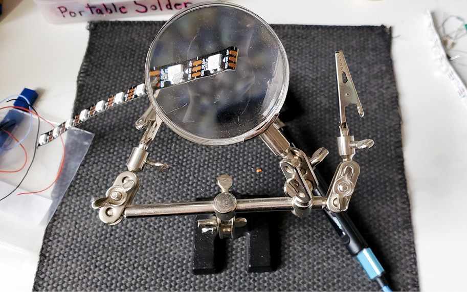
Figure 10.10 – Helping hands to hold your components
It helps to keep the component you’re soldering steady. Sometimes, if we move too much when soldering, the solder starts to turn a dark color and the solder has a glaze to it. Using a tool such as helping hands will help to avoid these issues.
Cleaning – brass sponge, tip tinner, and sponges
Cleaning your solder iron tip will prolong its use. It keeps it efficient too. You can push your solder tip into the brass wool and twist it a few times, and then dip the tip in a tip tinner. I highly recommend using brass wool and Chip Quik tip tinner. It will last you well over a year (depending on your soldering amount) and it will keep the solder iron tip healthy for prolonged use. I don’t use the wet sponge method, although others do. I’ve read on forums that the shock of the temperature change is bad for a tip. I find cleaning and tinning to be a useful process to protect my iron.
Solder iron stand (cradle)
You’ll need somewhere to put your solder iron while you’re soldering. For my portable kit, I have a minimal black tray with a metal stand for the iron to rest on. Do some searches on parts/supplier websites (listed at the start of this chapter) for the type of stand you want. Some solder stands have a roll holder for your solder or a sponge for cleaning. Always keep your iron in the stand when you are not using it. It’s a safe place to put your iron when you aren’t soldering.
Perfboard, stripboard, and flexible breadboard
When you want to make your circuit more durable and are looking to solder it, it’s a good idea to use a surface; this can be a perfboard (Figure 10.11), stripboard, or flexible breadboard. Perfboard is a board that has holes in it and it’s up to you to place your components through the holes. You then solder your components to each other and to the wires as needed. The board provides stability. The perfboard holes are independent of each other:

Figure 10.11 – Perfboard examples
Stripboard has strips of conductive traces along it; these copper tracks are on one side of the board. If you aren’t using the whole strip (for example, for a ground trace), you would cut the trace so you can use it for other connections. This can be done with a blade, cutting knife, or similar. You can get all colors and shapes of perfboard and stripboard so look around for ones that suit your project. Larger boards can be cut with a small hacksaw or placed against a table edge so you can carefully break them into pieces. I’ve also seen people using a drill bit to enlarge the holes and then snap the board. Be careful with the copper plating. Sweat from your fingers can cause corrosion on the board.
Lastly, there is also a flexible breadboard that you can buy for your wearable projects. These are interesting but do come at a higher price. It’s usually a good idea to have a few sizes, shapes, and colors to hand to suit all types of projects.
Solder iron
The section you’ve been waiting for! The most important part of soldering is choosing your soldering iron. There are a lot of choices and if you’re a beginner, you don’t need to buy the most expensive iron available. When I started out, I bought an Antex (https://www.antex.co.uk/home/) pencil-style solder iron (they have been in business for over 70 years). It felt great in the hand and did the jobs I needed easily. They have the choice of a burn-proof silicone plug and a variety of tips to choose from:

Figure 10.12 – A basic solder iron from Antex and a Miniware solder iron - very portable
For most of the components we are using for wearables, you’ll want to look for a pencil-style with 15 watts or more for your first solder iron. I still use the Antex solder iron (Figure 10.12) if I’m at my electronics desk area. However, my solder iron of choice is my MiniWare TS80 (now TS80P) (https://www.miniware.com.cn/). This is a USB-C (needs 9V power) soldering iron with hot-swappable tips and it heats up fast. I made a video of the tips being swapped out at 400°C temperatures (https://www.youtube.com/watch?v=WnVHVfRakTc&t=1s), and you can see, in Figure 10.13, I'm swapping the tip out from the hot solder iron. You can control the temperature, and other settings are configurable. Most solder irons have tips that can be replaced and are of different styles. I have a chisel tip, for example, that has an angle that makes soldering certain types of components easier. We each have our preferred types, so you’ll have to try different tips to get a feel for them:
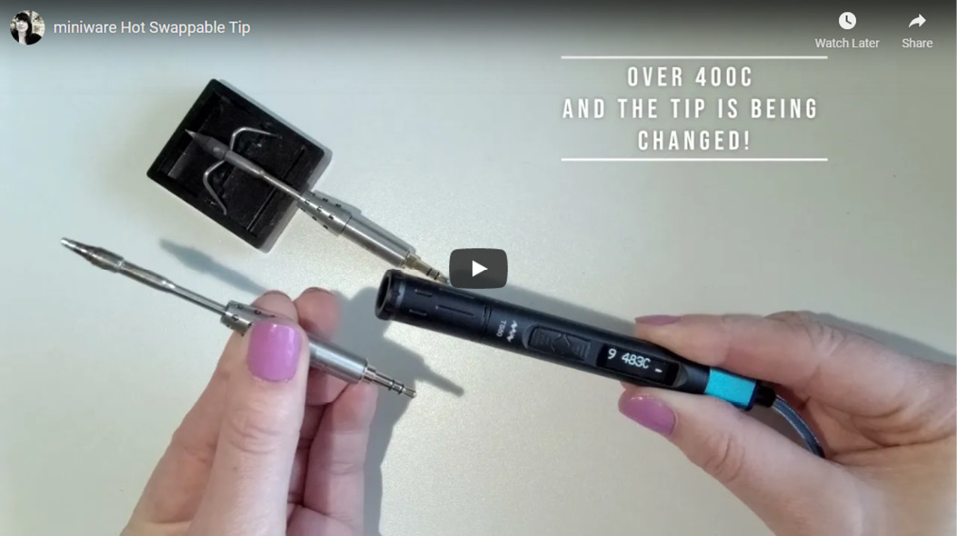
Figure 10.13 – Hot-swappable tips, changing the tip at 4000C
The MiniWare is a top-range portable solder iron and there is also a mid-range that is highly rated in maker communities: Pine64 Pinecil (https://pine64.com/product-category/pinecil/), which heats up in 12 seconds and is powered through USB-C or a DC5525 jack. If you enjoy soldering, it is worth investing in a good iron that you’ll keep for years. Other brands that are highly recommended include RS Pro (https://uk.rs-online.com/) and Weller (https://www.weller-tools.com/index.html), who make good-quality tools and solder irons.
I would recommend getting a starter soldering iron, pencil-style, such as the Antex XS25 model, to learn and use your new soldering skills. For an iron you’ll love and look forward to using, you might want to invest in one of the portable types. At https://www.tinkertailor.tech/tools, you can find a soldering range.
Now that we have learned about the items that help us to solder, let’s get ready to solder our first items. Please always work slowly and be mindful. Almost everyone I know who has soldered has burnt themselves at some point over a silly mistake, myself included.
Activity 10.1 – Resistor practice
After prototyping your project, if you want to keep it, you might want to try soldering. Soldering components adds durability and reliability to connections. Using a breadboard is a temporary solution to test our circuit. Often, and you may have already discovered this, the wires fall out or bend, or components get disconnected. It can be very frustrating. Also, often it can end up looking like a bird’s nest with a mess of connections and wires everywhere.
We can use conductive thread to sew connections to fabric, which will also allow for a more permanent solution; however, if your circuit needs to travel down a leg or other large distance, there can be signal strength issues. The resistance of the threads increases over length, and remember that resistance is a current-limiting property. We can use conductive fabrics though as these will carry the current over much longer distances and they allow for a lot of creativity too.
For learning to solder we’ll need the following:
- Resistors, bulk of any value, LEDs, and a 220 Ohm resistor.
- Protoboard or perfboard, 22 AWG wire in red and black, heat shrink larger than a resistor.
- A solder iron, solder, wire strippers, side cutters, and helping hands are useful.
Practice first – grab some resistors and perfboard so we can practice. Practicing is the best way to learn and build up confidence. After looking at the photos in the figure, let’s follow a few steps to practice. Remember, we all started with a similar activity, and it takes a little time to get a feel for it. Figure 10.14 shows the process we will follow. You should wear safety goggles, and work somewhere with good ventilation when soldering:
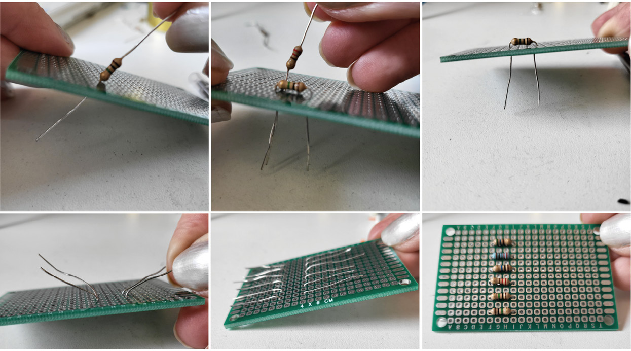
Figure 10.14 – Pushing resistors into a protoboard and opening the legs so it stays in place
Here are the steps to make our first solder connection:
- Holding your perfboard, push each leg of the resistor through one hole. After the resistor is through, pull the legs apart slightly to anchor the resistor in place. Feed through several resistors.
- Heat your solder iron. When it is at temperature (320°–420° depending on the solder you are using; the solder packaging will tell you), tap the solder to the tip of your soldering iron. The solder should just coat your soldering iron tip slightly. This won’t be used to solder with, but it helps the conductivity of our soldering.
- Hold the iron tip against the two areas you want to solder. Hold the solder iron tip so it touches both the leg of the resistor and the metal of the perfboard surface. Hold the tip against these two surfaces for a few moments so it heats up (Figure 10.15). There shouldn’t be any bubbling. If it bubbles, it’s too hot – remove the tip to let the surface cool:
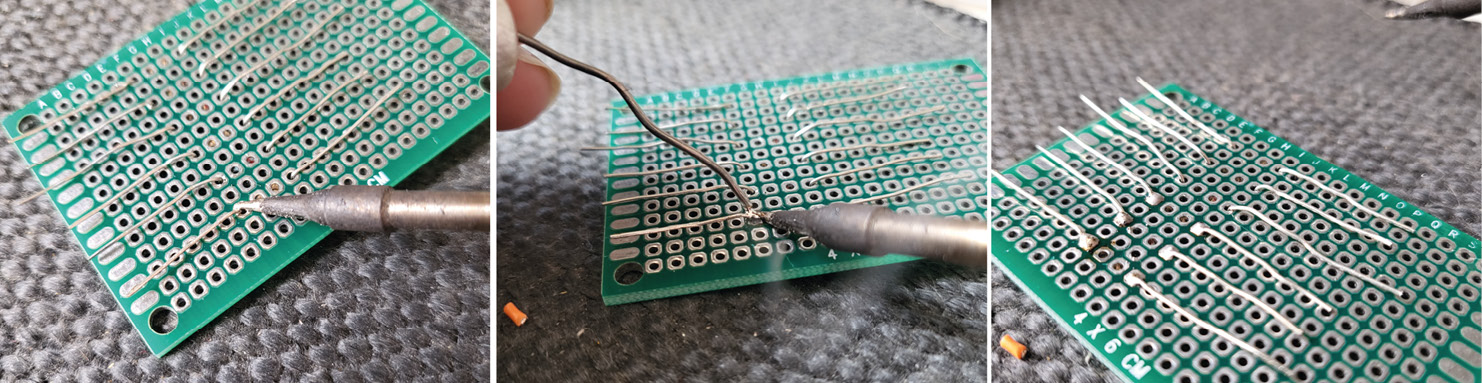
Figure 10.15 – Holding the solder iron in place and gently adding solder
- When both surfaces are heated, touch a solder strand to them. You want this to melt and flow; if it is flux core solder, there will now be some bubbling as it melts and heats. This is normal. Keep pushing in solder until there is a small mound forming.
- When you can see a small mound of solder, remove both the solder and the iron tip.
- Let the joint cool for a moment. This should harden into our solid solder connection between the resistor leg and perfboard. It will take time to be able to correctly judge how to get a feel for the amount of solder and the time to heat the components.
- When you have finished, clip the ends of the wires that are sticking out (Figure 10.16). Hold your cutters against the ends and clip – be sure to hold your hand over as you cut as they tend to ping off:

Figure 10.16 – Cutting the ends of our soldered wires
Keep practicing until you feel confident to try our next activity: soldering an LED with its resistor.
I love soldering so I hope you have a good experience too. Soldering will open a lot of possibilities for your wearables. There is no rush to move on so take your time and enjoy this learning process!
Activity 10.2 – Soldering an LED, resistor, and wires
Practice over… now that you’ve had a chance to practice, let’s try a challenge. This time, we will be soldering a resistor to an LED, then soldering two wires, one to each leg, and lastly, putting heat shrink on to protect our work.
I would read through this section in its entirety first and then go through it again as you solder.
To do this activity, you’ll need, as shown in Figure 10.17, an LED, a 220 Ohm resistor, heat shrink, and two wires. Also, you’ll need a coin cell battery to test that it works:
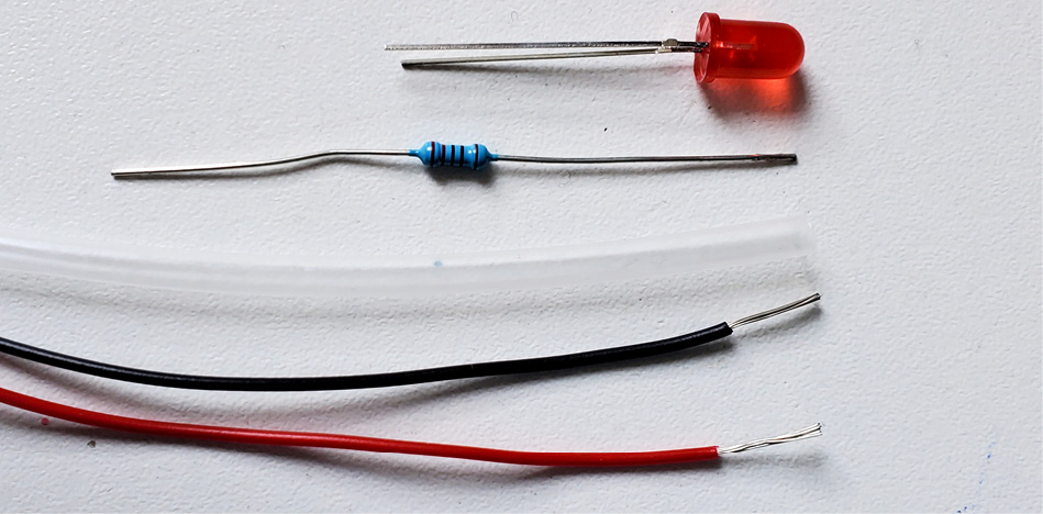
Figure 10.17 – Items needed for this activity
Don’t forget, you can use other resistor values if you don’t have a 220 Ohm; if you use a 330 Ohm, the LED won’t be as bright, but it will still work. Now that you’ve collected the items, let’s start:
- Strip the wires. The wire stripping tool looks like a pair of scissors with channels on the side. There are different types and sizes. Match the channel size with the size of your wire. If it is too small, you can break the wire and pull part of it out. If it’s too big, it just won’t strip the wire. Put the end of your wire into the jaws, squeeze the handle, twist the wire slightly, and then pull it out (Figure 10.18). The insulation should come away from the wire as you pull:

Figure 10.18 – Using wire strippers
You don’t need a wire stripper; you can do this gently with a pair of cutters. Just apply light pressure so you can feel the wire plastic covering cutting through, rotate your cutters, and then pull. You only need a small amount of wire exposed; don’t over-strip the wire.
Now that we have our wire prepped, we will try soldering an LED so that it has a resistor on it and wires to connect it to our wearable.
Silicone Wire
You might notice how soft silicone wire is. With this wire, you can usually just pinch off the amount needed. With your nails pressed into the end of your wire, pinch and then pull.
Now that the wires are prepped, let’s wrap the resistor on the LED leg.
- Wrap the resistor around the ground leg. This is the shorter leg of the LED. Don’t worry if it moves around, as the solder will hold it in place. Figure 10.19 shows the wrapping of the resistor in the photo on the left:

Figure 10.19 – Wrapping the LED leg and resistor for soldering
- After the leg and resistor are wrapped together, tape the component to a soldering mat with masking tape to hold it in place. Apply heat from your solder iron to both the leg of the LED and the leg of the wrapped resistor at the same time. You’ll have to maneuver the iron to touch both items. Once they have heated up, apply solder to this area so it flows between the gaps. It’s satisfying to watch.
- Move your solder iron and solder along these gaps between the resistor and LED leg. Watch as the solder fills this area and coats it; this is shown in the middle photo in Figure 10.19.
- Once soldered, do the pull test. Pull your resistor and LED to make sure your soldering holds.
- Looking at the photo in Figure 10.19 on the right, wrap the black wire (stripped end) around this same leg with the resistor. Wrap it at the end of the existing wire. After you have wrapped it, solder it using the same process. Hold the solder tip to heat the wire, then add solder to cover the connection of both the exposed wire and LED leg.
- Cut the resistor leg that extends beyond the black wire.
- Wrap the red wire around the power leg of your LED (Figure 10.20). Solder this wire in place, just as we have done for the previous two soldered connections. Cut the LED leg that extends beyond your red wire. The wrapping, trimmed, and soldered legs are shown in Figure 10.20 (right):
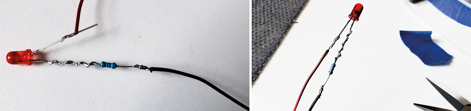
Figure 10.20 – Wrapping the red wire and soldering it
- After both legs are soldered, and you’ve done the pull test, put heat shrink around each leg. Slide the heat shrink around one leg and then the other. Make sure it covers the entire area you soldered. See Figure 10.21 showing the clear heat shrink added:
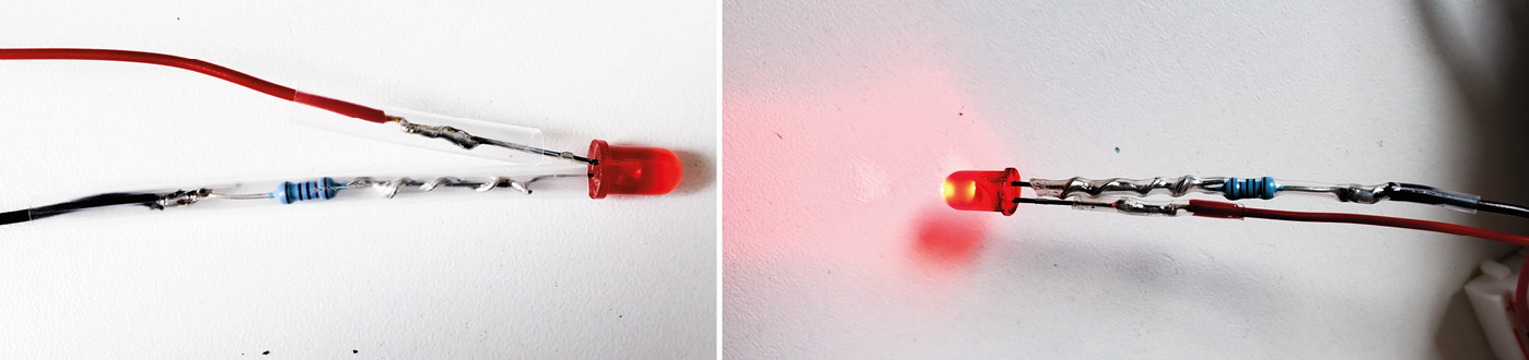
Figure 10.21 – Heat shrink added to each leg (left) and the working LED
- Once the heat shrink is in place, use a hot blow dryer, or a heat gun (a lighter can be used but hold it far away from the heat shrink!), and heat it slowly. You’ll see it get tighter and smaller around the circumference in size. It will start to fit tightly around this soldered area.
After the heat shrink has shrunk to fit snugly, using a coin cell battery, test your circuit works! (Reminder power + on the battery to the red wire, and negative – to the black one.) You now have a working LED with an integrated resistor; that’s amazing!
Now that you’ve done a more complex solder job, let’s look at something that you will find yourself doing often: soldering in headers. It is often the case that when we purchase a new component, it can come pre-soldered, or we can choose to solder it ourselves. This is a good option for wearables because soldering in wires is usually the better choice so that we can integrate them into clothing.
Soldering in plain headers
An important soldering skill to have is to solder pin headers on your components. If you can add this skillset to your soldering knowledge, then you’ll be able to create a variety of projects.
To start with, prepare the header strip by cutting it to the length you need. Some components come with the headers, so they are already the correct size. In Figure 10.22, the top left shows the breadboard with header pins pressed into it. Be sure to press long pins down:

Figure 10.22 – Soldering plain headers on a QT Py
Now that the pins are in, place your component on top, as in Figure 10.22 (bottom left). I used a flux pen to go over the top of the header pins that are exposed, as in Figure 10.22 (middle). When soldering, be careful not to touch the breadboard with your soldering iron, because it will melt your breadboard immediately! Then, as previously, hold the solder iron tip against the pin and circuit board; think of it as holding the side of the solder tip against it. Make sure they get hot and then hold the solder to it as well.
You’ll want to do a tack solder.
Tacking Solder
Tack solder is a solder point to help hold the pins you are soldering, in place. Solder one of the pins on one side of the board – I chose the top right – and then solder a pin on the opposite side of the board, say bottom left, for example, tacking it in place.
Solder all the pins, then check them to see that they all have good coverage, but not too much, and that none have solder overlapping to the pin next to them. This is called a bridged join. We can check for bridges with our multimeter.
Checking for bridged joins
Using your multimeter’s continuity setting (the symbol that looks like a speaker as it will make a noise), we will check whether the soldered pins are connected where they shouldn’t be. Figure 10.23 (left) shows holding the two ends of the multimeter touching so it is a connected circuit that it registers a value and will make a sound:

Figure 10.23 – Checking for bridged connections using a multimeter
When there is no connection, the reading is open loop (OL), as we’ve seen previously in Chapter 2,Understanding and Building Electronic Sewable Circuits. Let’s check whether we have bridged our connection:
- Hold one probe to one pin on the circuit board that you’ve soldered.
- Hold the other probe to the pin next to it.
- Does your multimeter make a sound?
- No? Great! There’s no bridge.
- Yes? Oh-oh, you’ll need to remove the solder to fix that pin so it doesn’t touch the one next to it.
Do this for all pins that you think might be bridged. You’re done!
Activity 10.3 – Other activities
The last thought on soldering: first, protection from helping hands for your board or components. I’ve added some protection to the crocodile clips of the helping hands that I have. You can do this too:
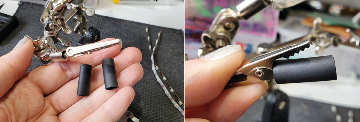
Figure 10.24 – Adding heat shrink to the crocodile clip on helping hands
You’ll need two pieces of heat shrink that are large enough to fit over the crocodile clips on your helping hands. I’ve used these black pieces (shown in Figure 10.24). Place one over one of the clips (Figure 10.24) and then place the other heat shrink tubing over the other clip. Then, using a heat source, hot air gun, hot hair dryer, and so on, warm the heat shrink consistently and evenly. Don’t hold the heat for too long in one place:

Figure 10.25 – Adding heat shrink tubing to a set of helping hands
See Figure 10.25, which has the heat shrink over both clips and is then shrunk over it. This will provide protection from physical damage when your components are held by the clips. Now that we’ve added protection for our components, let’s have a look at alternative ways we can connect our components.
Alternative ideas for connections
The ideas here are to show you that we can use other ways to connect. You can look at things you find that are conductive to see how they could form part of your circuit. For example, you can use the ends of your wires to create loops, similar to when we looped our LED legs. This time, loop the wire end and solder a connection to make the loop solid. Figure 10.26 shows a wire end (top) that has then been looped (middle) and has a solder applied to the loop (bottom):

Figure 10.26 – Wire with a soldered sewable end
This will create a stable connection that is easy to sew. Another possible solution is to use a safety pin in place of a crocodile clip. When we are working with fabrics, crocodile clips can cause damage to the fabric. They can mark it, or even cause small rips. If we get inventive and use a safety pin – which is made for fabrics – then we can use this as a connection for our components. In Figure 10.27, we see a safety pin that has been soldered with wire:
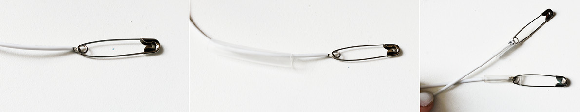
Figure 10.27 – A soldered safety pin with silicone wire
We could have soldered one side and left it as a wire or soldered it to a crocodile clip to connect to our circuit board. What I’m saying is, be creative with the connections that you need for your circuits. You don’t always have to buy something off-the-shelf if it isn’t suitable for your purpose. You can make it with your soldering skills! For further inspiration, Irene Posch explains needlework tools that have been adapted for electronic making here: http://www.ireneposch.net/tooling/.
Now that we’ve seen alternative uses for our soldering skills, let’s have a brief look into what to look for when we are soldering – how to spot errors, for example, and fix them.
What to look for when you’re soldering
Soldering takes practice and, over time, you’ll learn to recognize when you have the perfect solder joint. There are a few types of joints that you’ll see as you’re learning, and you may need to fix something you’ve soldered. Typically, it is too much heat, too little heat, or the wrong amount of solder that causes the most problems. Look through Figure 10.28, which demonstrates the way your solder might look and why. Most of the problems with soldering can be fixed.
In Figure 10.28, we see the following:
- A, which is the type of solder joint we want. There is an even distribution of solder that fills the hole around the component pin or wire.
- In B, the solder hasn’t stuck to the joint of our circuit board, so it has formed a ball and almost floats around the leg of what we are soldering. If you add flux to the pad and reheat, the solder will flow to that area as well and this will be fixed. This also looks typical of what might be called a cold solder joint. A cold joint means the solder didn’t completely melt. If not enough heat has been applied, the solder looks dull, has no shine, and the joint will be weak. Sometimes, when people fix this type of joint with additional heat, they add more solder. This can lead to too much solder on the joint and so you might have to also use the desoldering braid to just remove a little of it.
- Error C results in a bad connection; there isn’t enough solder applied. This can easily be fixed. Reheat the area and apply more solder so it flows and you get the volcano shape in A. This is sometimes called a starved joint.
- D is also a bad connection that will need reheating, and it also looks a bit like what’s called a disturbed joint. If, as you’re soldering, there is a lot of movement, especially when you are removing the solder and soldering iron tip, it can appear frosted or have darker color areas. Make sure you apply enough heat and only remove the solder iron and solder when you have let enough solder flow. Don’t hover around or move the iron tip for no purpose.
- Lastly, E is how a bridged connection will look, as was described earlier. The connection is across more than one pin, which will cause a lot of problems. You will need to remove the excess solder so there is no connection between them and then test it with your multimeter to be sure there is no connectivity.
Use Figure 10.28 as a quick go-to reference for checking your solder joints and what types of quick fixes you can do:
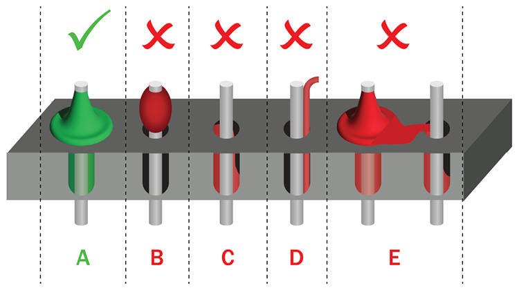
Figure 10.28 – Types of solder joint formations
There can also be discoloration of your solder if you’ve used too much heat. Sometimes, we hold our iron on the joint for too long because we just aren’t sure how much heat is needed. This can sometimes damage the pads we are soldering to. Also, sometimes as we solder, small solder spatters happen. These are little flecks of solder that flick and then stick to the board. If they come off while we are using our circuit, it could cause a short circuit. Always remove (with tweezers or a knife) any spatters that can occur.
If the soldering isn’t going how you’re expecting it, take a break, let the joint/leg/header and solder iron cool, and try again.
Clean!
Don’t forget, many soldering issues can be avoided if we keep our solder tip clean and tinned. Always brush your tip in the brass wool and then use a little solder or tinner to tin the end of your soldering iron.
I hope you’ve enjoyed our work with soldering. As a reminder, when soldering, follow these steps:
- Heat the iron; when at temperature, clean the iron and tin the tip.
- Steady the parts you want to solder using helping hands, or similar.
- Heat the joint – both the parts that you want to be connected together.
- Apply the solder and let it flow into the joint and circuit.
- Allow time to cool, undisturbed.
- Then, trim any wires or pins that need to be cut.
There are many reasons for varying results; it could be the temperature of your solder iron tip, the type of solder you are using, the wire thickness, or the surface of the circuit board. These variables will alter the time it takes for the solder join to form and it is only through practice that you will get a feel for it.
Now we will learn about sewing so we can continue our project from the previous chapter.
Sewing
After learning more about soldering and the advantages of soldering our circuits, to allow for durability and reliability, we will look at another making skill: sewing. As mentioned earlier, conductive thread isn't great over long distances due to the resistance. However. we can sew conductive textiles that we have cut in shapes to suit our designs. This allows a larger current to be sent through the material, and we can use this for creativity in our circuits too!
We are going to learn more about sewing through practice. We’ll use our wearable technology project from the hyper-body system we started to prototype in the previous chapter. First, let’s take a look at recommended items for sewing.
Sample items used for sewing
There are a few essential items you need for sewing, and many other optional items too. See what items you already have, and then you can build up slowly all the sewing supplies:

Figure 10.29 – Sewing supplies
If you want to give sewing a miss altogether, you can glue-gun fabric together, or repurpose old clothes. Then, you’ll mostly just need the seam ripper.
Cutting
Although sewing is connecting fabrics and items together, you’ll spend a lot of time cutting in various ways. Seam rippers are great for when you make a mistake, as you can quickly pull the seam back up again. Also, when we are modifying existing garments, the seam ripper will help us get into sewn areas such as hems, pockets, seams, and more. For cutting close to the thread ends and with a sharp edge, you might want a pair of thread snips. These are two sharp, pointy blades that cross over each other in a rapid scissor action. They are great for close thread cutting.
Fabric scissors/shears are a great idea if you will be making things often. Don’t use them for anything else! They will cut neatly and accurately without puckering or ripping parts of the fabric. Usually, these have a flat edge to place on a table and cut through the fabrics. You can also buy them with a slightly blunt nose, so they don’t catch or snag your fabrics. Pinking shears are an ideal tool to keep your fabric edges from fraying. Cut along the edges and you can achieve a neat finish. Lastly, rotary cutters are so quick to cut through several layers of fabrics against a metal ruler, and the edges will be the straightest of all the other methods. If you have a self-healing mat, the cutter will be fast and accurate and last for many years. The mat will also protect your surfaces.
Threads and fabrics
I’ve put threads and fabrics together, as the general rule is to use the same thread type to match your fabric. For example, if you have a cotton-based fabric, then use a cotton-based thread. You don’t have to follow this, and polyester threads can be stronger than cotton. I use Gütermann threads as I’ve had no quality issues with them. You can also buy clear or invisible thread for areas where you don’t want the thread to be noticeable. Conversely, you can buy threads that are for embellishment, top stitching, and to add a highlight or interest to the stitches that you make.
Fabric for wearables was previously discussed in Chapter 8, Learning How to Prototype and Make Electronics Wearable, so I will iterate that denim, scuba or neoprene style, and felt are my fabrics of choice. They have durability and curve well with the bends of the body.
Needles, pins, and clips
You’ll need a sewing needle for sewing by hand, and a needle threader will revolutionize your life. Don’t waste your time struggling to thread a needle. The conductive threads are notoriously bad for having tiny wisps of metal coming off them, making threading even more difficult. Use a threader and it will end all frustrations. If you haven’t used a needle threader before, it’s a great (almost essential tool when sewing with conductive thread) way to make needle threading pain-free. Figure 10.30 illustrates how to use it. Holding your needle and the threader, push the metal wire of the threader through the needle eye:
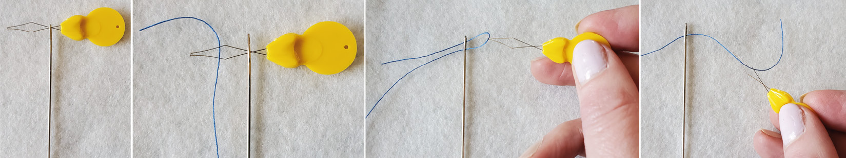
Figure 10.30 – Using a needle threader
Once the threader is pushed through, put the thread through the threader. Then, pull the threader out of the needle eye. The thread follows and your needle is now threaded.
You’ll also need a selection of pins to pin or hold your fabric together while you sew, but I also use wonder clips when the fabric is likely to mark, such as neoprene. You may also want to get or make a pin cushion or have a magnetic tray to keep your pins in. Lastly, an awl can be handy for poking holes in fabrics so you can thread wires through.
Other tools
Other various items you may need include a tape measure that is very flexible and has metal ends. These tape measures for sewing are handy when measuring, especially when used around body parts for making. Chalk is very useful for marking your circuit on the fabric. Placement is very important so making chalk markups on the fabric is a great idea. It will easily rub off. You can buy chalk specifically made for pattern cutting, and chalk in pencil form with a brush on the end to help it to rub off. A seam gauge with an adjustable notch can be helpful for accurate measurements. You can create an adjustment and slide the notch to where it represents the area we are focused on. You can then use the ruler with the correct distances mapped out with the notch. To keep your fabric looking great, you should have an iron handy. Using an iron to press interfacing, press a conductive fabric with lining in place, or flatten seams will improve your wearable. You can iron sticky backings onto conductive fabrics. You can purchase a special mat that sits under and around a sewing machine, so you can use the surface for ironing. I have a mini-iron that looks like a small travel iron (no bigger than my hand) and works great for wearable projects, which can often be small. There are also small desk stands for an iron, which allow you to continue ironing on your desk area. This includes mini quilting irons for fusing and spot ironing; you can add small patches of fusible materials and it’s a great way to iron very small places often inaccessible by any other means. Lastly, you can also get various filled shapes (a tailor’s pressing ham) that you can use to iron where the fabric might curve.
A glue gun is a useful tool. It can cover wire that is exposed or help stick our components in place so they don’t move when we sew. You can also buy glue sticks in different colors. Also, a sewing machine is a great item to have if you do continue with sewing. This will help to speed up the process of sewing and allows for professional results. No more wonky stitches! There are many types of sewing machines and this falls outside the scope of the book, but I have a few Brother machines (https://global.brother/en). TYSEW (https://www.tysew.co.uk/sewing-machines) has a huge selection and offers demos, and they are great with advice too.
Now that we have our sewing supplies, let’s start putting our wearable together.
Putting your wearable together
We have our electronic components and we know they are working because we made a low-fidelity prototype with them and the code. Now, we can transfer this prototype to a more stable version by sewing and soldering it in place. Let’s make our wearable in a few steps.
Activity 10.4 – Sewing a pocket for the heat pad
For the heat pad, I’m making a pocket for it to sit in. Because we want the wearer to feel the warmth, I’m using a thin linen fabric. You’ll want to choose a fabric that has stability but that is thin enough to allow the heat to transfer to their back. Measure out the amount of fabric needed and cut wider and longer than the heat pad to allow extra fabric for a folded seam for the edges. Figure 10.31 shows the measuring with the heat pad. Linen can fray, so we want to turn the edge of our fabric inside to create a nice edge that doesn’t come apart:
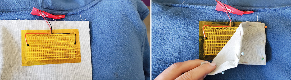
Figure 10.31 – Measuring out fabric for a pocket
This can be ironed flat (Figure 10.32) to allow it to stay neatly in place when we pin and sew it:
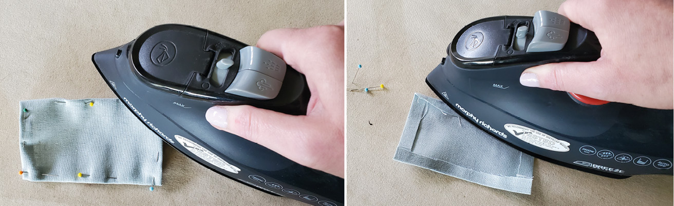
Figure 10.32 – Ironing the fabric for crisp edges
In Figure 10.33, we see the jumper on the left, and then placing our components where they will fit nicely for this purpose in the middle and left:
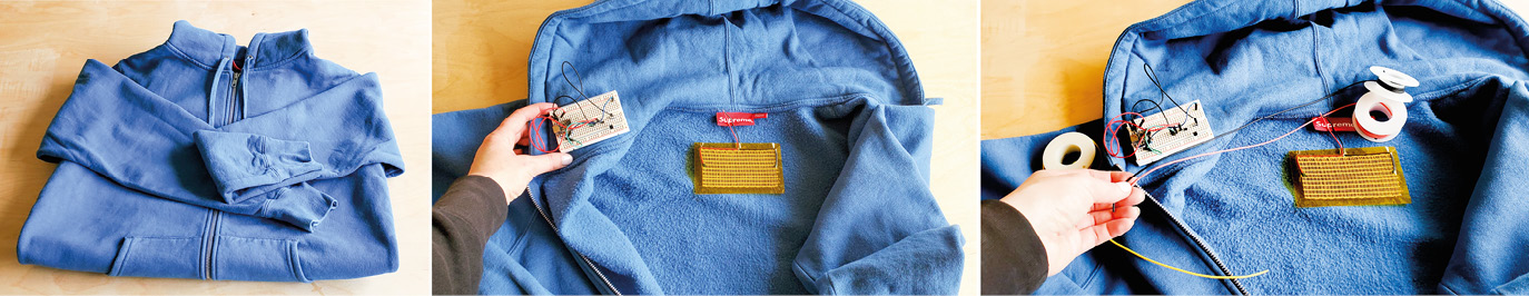
Figure 10.33 – The jumper and placing components for planning the wearable
Pin the material in place and before we sew it with our heat pad inside, let’s solder longer wires onto our heat pad. Measure out the wire length needed for the heat pad to the area where the other components will be. Then, strip the ends of the wires. Once they have been stripped, twist them with the exposed wire ends of the heat pad (Figure 10.34), and solder them together:
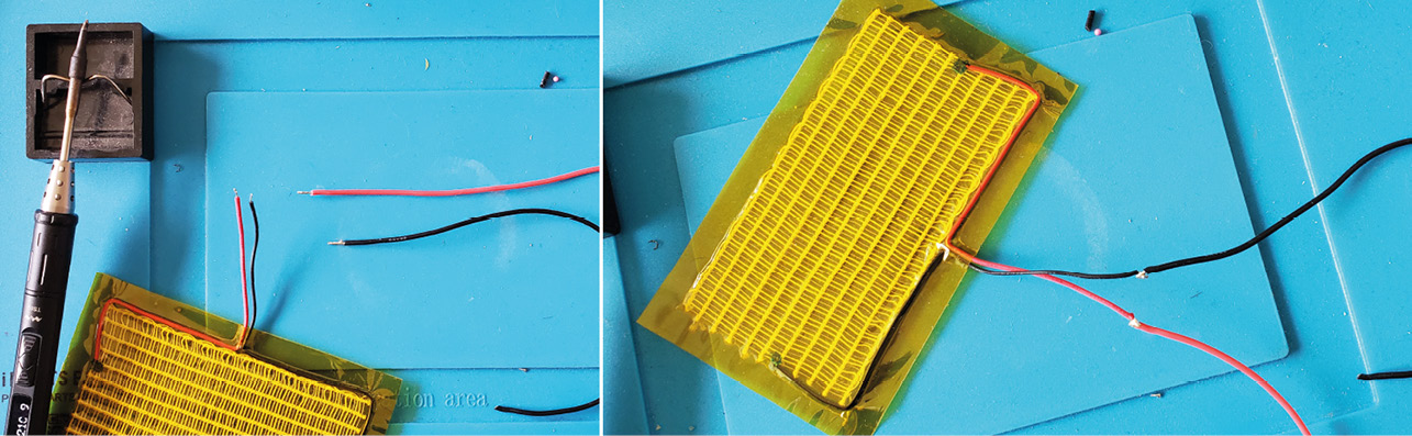
Figure 10.34 – Stripping the wire ends, twisting them together, and soldering
You’ll notice there is a potential issue with how we’ve left our soldering. Can you tell what it is? If you noticed that there is a potential for a short – you are correct! The black wire and red wire both have exposed conductive areas right where they would meet if the wires were moved together.
How can we fix this? Using heat shrink, we can cover each wire, and shrink it. Then, both wires will be insulated, and they don’t have the potential to touch anymore. After you have added the heat shrink to each wire, let’s solder the parts needed to make the heat pad work – the transistor, resistor, and diode. In Figure 10.35, I’ve mapped my circuit out again in my notebook because I don’t want to make any errors. It’s also handy to refer back to in the future:

Figure 10.35 – Mapping out and making the circuit
Curl the ends of the diode, transistor, resistor, and wires so you can connect them together. After connecting these parts, solder them together. You’ll want to add heat shrink on these as well.
We could have soldered these to perfboard but it is a hard surface and we want this to be in the hood part of our clothing. This wouldn’t be comfortable, so I opted to use the same technique that we did with the LED soldering in Activity 10.2. Now that we have everything we need for the heat pad, let’s sew it into place. With your needle threaded, let’s sew the heat pad pocket – with the heat pad inside and wires outside – to our garment:
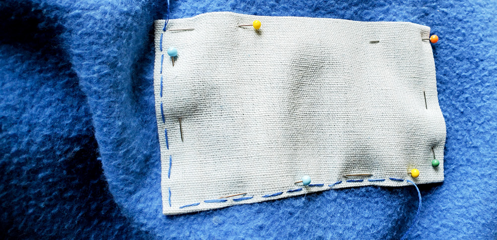
Figure 10.36 – Stitching the pocket
I’m using a wide stitch on the inside of the jumper and a very small stitch on the outside to hide it. We’ve done this before, and it’s called a hidden stitch. You can stitch for whatever suits the jumper you are working with.
After our pocket is stitched all the way around and the heat pad is fully enclosed, with wires sticking out, we can move on to soldering our circuit before we put it in the hood of our garment.
Activity 10.5 – Soldering the QT Py ESP32-S2
Now that we’ve completed the first part of our wearable, we will finish soldering the connections to the QT Py, and then we can place it all inside the hood. Strip the ends of the wires that you’ve soldered to your diode and resistor for the heat pad circuit. You’ll also need a ground, power, and pin wire for your NeoPixel. Strip the ends of these wires too.
With your QT Py board secured in helping hands, push the wire ends through the pin number you are soldering. See Figure 10.37 for an example on pin A3. I’ve pushed the wire through, folded it over, and then soldered it into place. Do the same for pin A2:
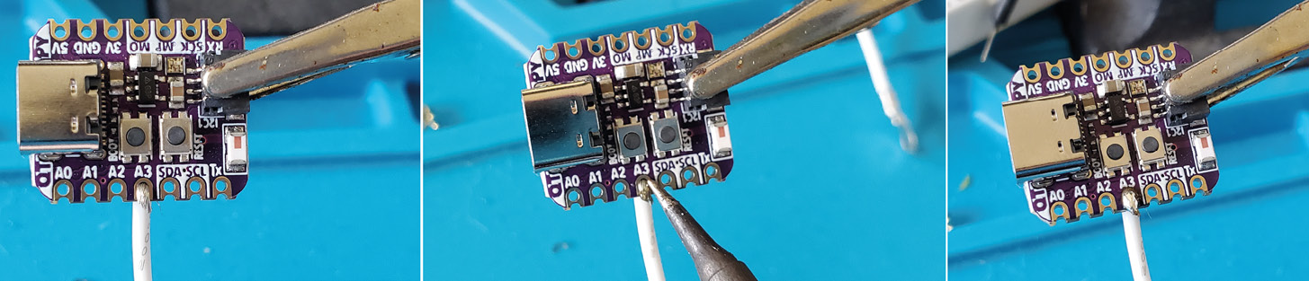
Figure 10.37 – Soldering wires to the QT Py
Adding a second wire is shown in Figure 10.38. Repeat this process for all the wires you need in your circuit, such as power and ground. I trim the connections after they have been soldered:

Figure 10.38 – Soldering a second wire
Add the connections for your NeoPixel too. Now that we’ve soldered the connections, I’m going to add power to our circuit. So, let’s do another activity!
Activity 10.6 – Adding power
There are power pads on the bottom of the QT Py board. They are marked as + for power and – for ground (Figure 10.39). We need to add solder to these pads so that we can then add a wire. First, add flux to these pads to help the flow of solder to them. Heat your solder iron, and when it’s at temperature, touch the pad with the iron, and wait a moment while it heats up:
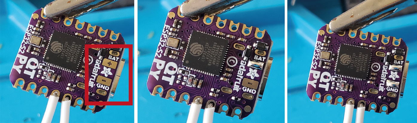
Figure 10.39 – Applying solder to battery pads
When it is hot, touch the solder to the pad, and watch as it melts onto the pad surface. When it is covered, remove the solder and your iron. Do the same for the other pad. You want enough power pads solder so you can heat it up and put the wire on to it. Now that both pads are coated, touch the black ground wire of your battery to the ground connection. Heat this up very steadily. The wire will start to sink into this space. When it has melted in, remove the iron carefully so you don’t disturb the wire at all. This will take some practice.
Adding an on/off switch
We will need a switch added to our circuit. Without it, as soon as we solder our power to the QT Py, it will turn it on. Using a switch of your choice (I’ve gone for a sewable type), solder the wire from the QT Py power + tab on the underside of the board to one end of the switch. See Figure 10.40 showing the switch with a soldered wire on a sew tab connection. Try to keep the hole so we can sew this to our jumper:

Figure 10.40 – Soldered switch with wires
We need to complete the circuit. Check that your switch is off before soldering! Think of the switch being placed between our wires that will carry the power. With that in mind, solder the battery power wire to the other side of this switch to complete the circuit, as in Figure 10.41:

Figure 10.41 – Soldering the other wire, and the complete switch with battery and QT Py
We now have a working power connection, so let’s sew this circuit board and our electronics into our item of clothing.
Activity 10.7 – Sewing the Adafruit ESP32-S2 QT Py into your garment
We’ve been very busy soldering and preparing our circuit so that we can add it to our clothes. The completed wearable is shown in Figure 10.42. So, what last steps do we need to do to finish our wearable? We need a seam ripper to gently pull apart a seam in the jumper so we can slide in the circuit. We can then sew this in place:

Figure 10.42 – Our completed send a mood wearable
It can be a good idea to first sew the circuit to a piece of soft fabric, such as felt, for example (Figure 10.43). Then, you only need to sew the felt in place. Let’s start by sewing our circuit to a piece of felt. When you’ve finished, start to pull apart the seam in the hood of your hoodie, or create a cut to place the electronics inside:
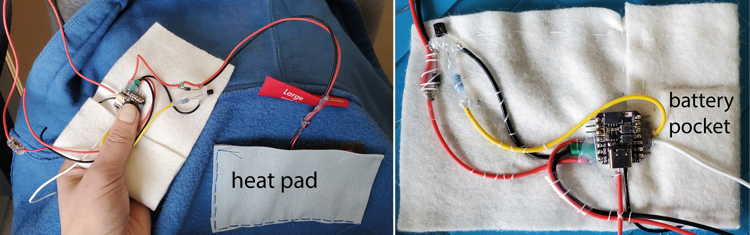
Figure 10.43 – Sewing your electronics to a felt base
After you’ve made an opening, push the electronics on the felt inside (Figure 10.44). Sew them into place. You can sew all the way around your microprocessor, or just structurally where it needs support. Sew the hole you made closed:

Figure 10.44 – Creating an opening, and hiding the electronics inside
Lastly, measure, place, and sew your NeoPixels. I’m using a leather holder for them so they don’t move, but you could use sewable NeoPixels, or sew other types of NeoPixels to the jumper:
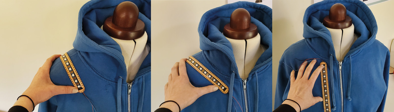
Figure 10.45 – Deciding the placement of NeoPixels
When you have finished, turn it on, making sure you have the Wi-Fi network working so your QT Py can connect to the internet, and go online to the URL you set up at io.adafruit in the previous chapter. You can control the heat pad and NeoPixel colors from your browser. You can see multiple photos of the completed jumper in Figure 10.46:
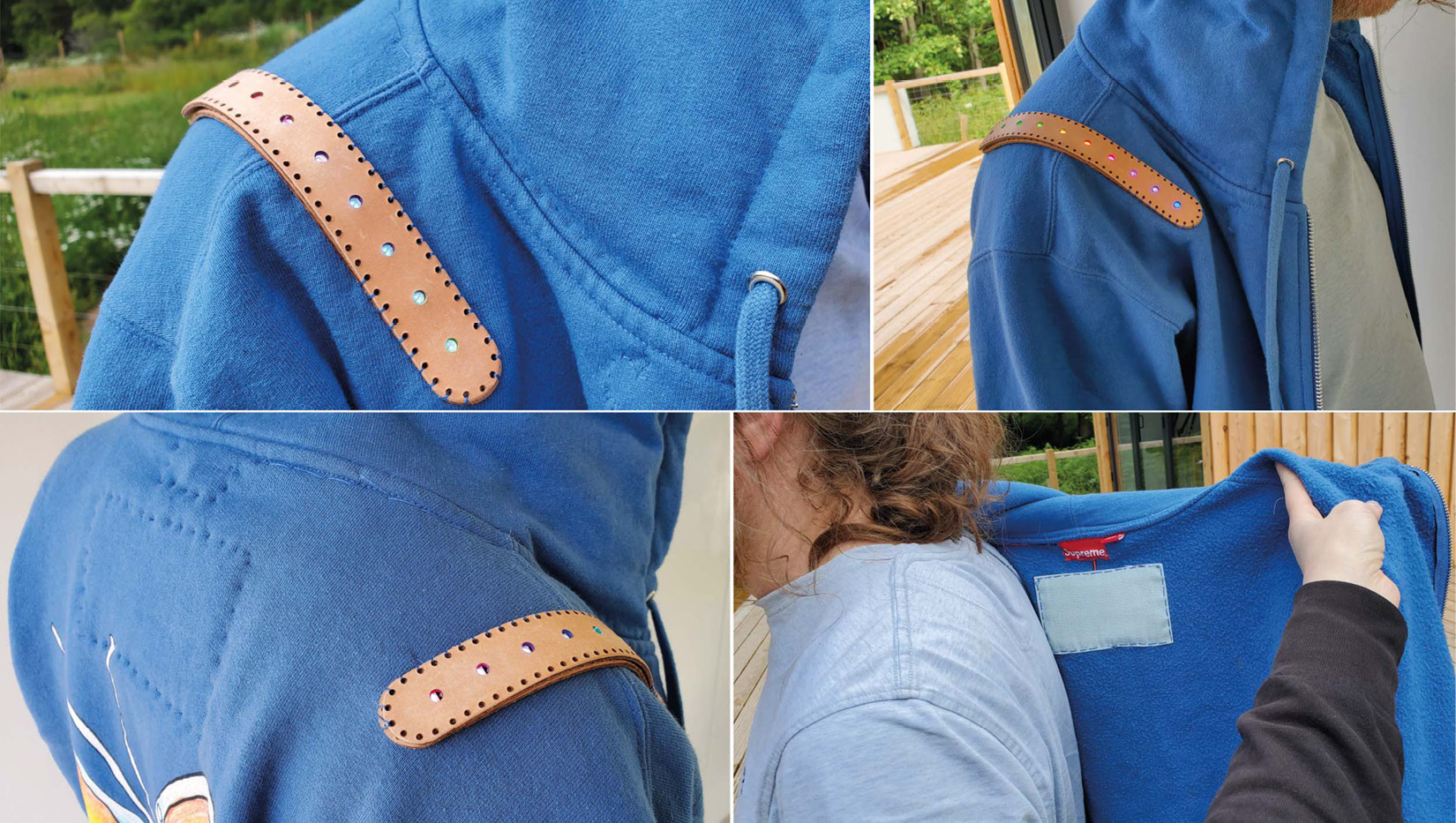
Figure 10.46 – The completed jumper outside and the heat pad against the back
You can build upon this circuit. Maybe add vibration, sound, or more lights too. You might also want to create a backdoor to access the electronics. You can do this by creating a flap with a snap so you can open and close it when you need access.
The last step is to give this jumper away to a friend or family member and send them a hug!
Summary
This chapter has covered a lot of new techniques and skills. We learned about and practiced soldering, and then we looked at sewing in more detail. These two skills were then used to complete our previous project. The practical nature of the learning should give you a much better understanding of some of the techniques. We completed a wearable that we can use with our family and friends, and we finished an IoT project wearable. This was an exciting chapter, and you will hopefully have time for more practice before jumping into the next chapter.
In the next chapter, we get into the theory behind our informed wearables, and this is by looking at Design Innovation as a process. Another exciting chapter is ahead!
Review questions
- What advantages are there for soldering a circuit?
- Why shouldn’t we sew all our circuits?
- What is a bridged connection?
- How can we tell whether we have a bridged connection? What tool can we use?
- Can we remove solder from our wire/connection?
- What are some good fabrics for making wearables, and why?
- Why would we use a seam ripper?
- What is the advantage of using IoT in a wearable?