
4
Implementing Arduino Code Using Gemma M0 and Circuit Playground
Gemma M0, Circuit Playground, and other sewable boards are a great way to add more interaction to your wearables. As you learned in the previous chapter, their different sizes, functions, and I/O ports make them appropriate for different uses.
In this chapter, we will focus on learning through building a practical application with a Gemma M0 or Circuit Playground board so that you can expand the capabilities of your circuit. We will also explore flex sensors and the many ways to alter, use, and make them. Once you’ve considered their uses, you will connect a circuit. We will also read about how flex sensors have been used in research. Reading how components are used is a great way to inspire your projects. After that, we’ll spend some time learning about the Arduino IDE, which you’ll use to program your wearable. This will be followed by testing your circuits.
By the end of this chapter, you’ll have a better understanding of designing, prototyping, and using the Gemma and Flora boards. You’ll add flexibility to your wearable with an off-the-shelf flex sensor or one you’ve made. This will prepare us for the chapters that follow in which we will learn about the inputs and outputs that can be added to wearable projects. We will finish this chapter by hooking up and programming a Gemma M0 with a flex sensor and a servo motor!
In this chapter, we’re going to cover the following main topics:
- Prototyping accelerometer and flex circuits
- Understanding flex sensors
- Research and innovation
- Troubleshooting
- The Arduino IDE
Technical requirements
In the practical part of this chapter, you’ll use the Circuit Playground and Gemma M0 boards and create flex sensors. You’ll also connect a flex sensor and servo motor to the same circuit. To follow along, you’ll need the following items for the circuits. You can choose or swap items out from the following list:
- A Circuit Playground/Gemma M0 board and a micro USB cable
- Various flex sensors and a stretch sensor
- Conductive fabrics/textiles
- Velostat resistive plastic
- A 10KΩ resistor
- A servo motor
- The Arduino IDE: https://www.arduino.cc/en/software
Prototyping accelerometer and flex circuits
Previously, we connected our Circuit Playground board and programmed its LED to blink through the Arduino IDE. Now, we’ll add to our skills by using an example from Circuit Playground and modifying it. We’ll use the built-in accelerometer for this. We have a lot of exciting ground to cover, so let’s jump straight in with our first activity.
Activity 4.1 – Hello_Accelerometer
Let’s have some fun checking out one of the sensors on our Circuit Playground board to get to know it better. The accelerometer measures motion in your wearable. We will use the included example code from Adafruit. Plug in your Circuit Playground board and choose the correct board and port, as we’ve done previously.
As a reminder, go to the Tools | Board menu and select your board. Then, go to Tools | Port and select your port. The Arduino IDE may have found your board and port when you plugged it in, so you may not have to do this. Once your board has been found on the correct port, open the sketch.
The sketch can be found by going to File | Examples | Adafruit Circuit Playground | Hello_Accelerometer, as shown in the following screenshot:
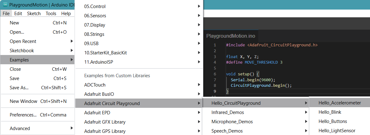
Figure 4.1 – Opening the sample sketch
Once the sketch is open, upload it to the board. Remember that the upload button is the second button from the left and looks like an arrow pointing to the right. Check for the confirmation message stating that the upload was a success – that is, upload complete – as shown in the following screenshot:
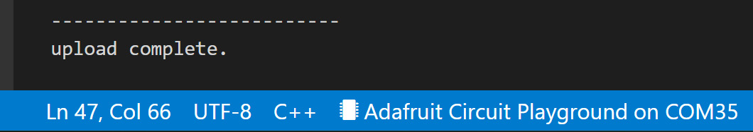
Figure 4.2 – Upload complete
Let’s check if it’s working. For this, we’re going to open Serial Monitor. This is the last icon on the top right-hand side of the Arduino IDE and looks like a magnifying glass. Click the magnifier icon, as shown in the following screenshot. The serial monitor is integrated with Arduino 2.0, and it can be used as a debugging tool, to test out concepts, or to communicate with a microcontroller board:
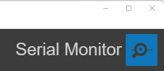
Figure 4.3 – The Serial Monitor icon
Once Serial Monitor is open, as shown in the following screenshot, make sure the baud rate is the same as declared in the sketch; that is, 9600 baud. Then, move your Circuit Express board. You will see that the values change based on the movement and orientation of the board. What’s going on?
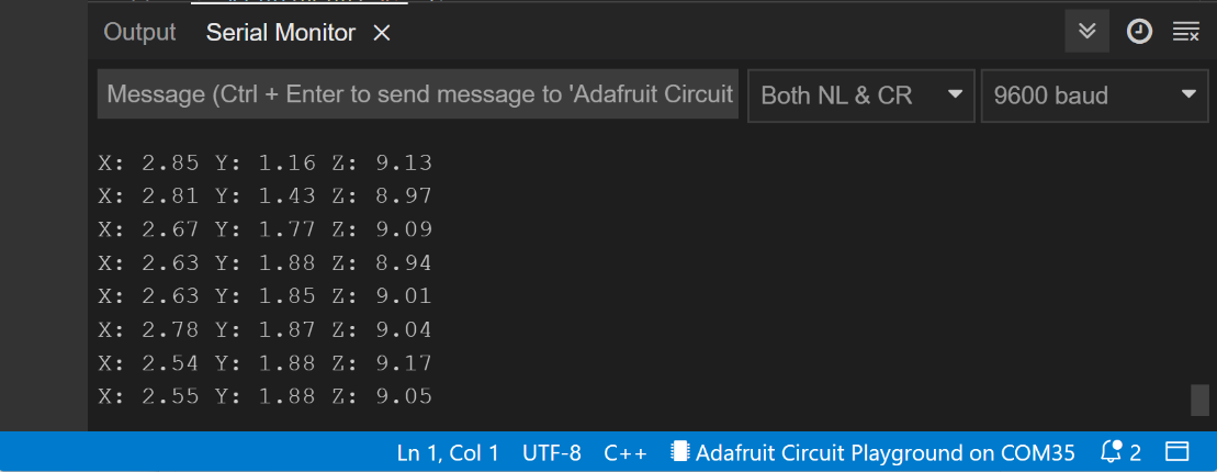
Figure 4.4 – Serial Monitor
Let’s break down the code to understand it more. The first line is an #include statement. This adds libraries to the sketch and links them. These are premade files that contain code that adds a lot of functionality to our sketch. Then, there is a declaration of values that will be used in the sketch. In this case, we will need to use a float. float allows us to use decimal places in numbers.
Here, we create three instances of a float type – namely X, Y, and Z – that correspond with the directions of the accelerometer. We can also declare it in three separate lines.
The X, Y, and Z variables are used as directions:
- X is clockwise and counterclockwise.
- Y is for twisting the board left to right.
- Z controls back and forth motion.
You’ll recognize the next part of the code: the setup() function. This contains our initial settings and a new function called Serial.begin(). We will use it in almost all of the code we write. This allows us to use Serial Monitor and send messages to it. It is very useful for finding errors in our circuit and reading messages to see what is working.
In this sketch, it will be used to display the values of the sensor. We only need to set the speed of the connection. As shown in the following screenshot, I chose 9600 baud. This must match the speed “baud” in the Serial Monitor window:
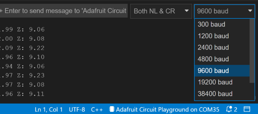
Figure 4.5 – Choosing the matching baud rate
Lastly, we must create an instance of CircuitPlayground by appending the .begin() function. This will allow us to access the code in the library so that we can use CircuitPlayground in the sketch to add features and functions:
#include <Adafruit_CircuitPlayground.h>
float X, Y, Z;
void setup() {
  Serial.begin(9600);
  CircuitPlayground.begin();
}
Next, let’s look at what the code is doing in the loop() function. Here, we allocate a value to the three float variables we defined. We allocate position X to the value of the CircuitPlayground X coordinate.
This can be done by using a prewritten function called .motionX(). The same follows for the other two float values, where we will use two other functions, .motionY() and .motionZ(), for the Y position and Z position coordinates, respectively:
void loop() {
  X = CircuitPlayground.motionX();
  Y = CircuitPlayground.motionY();
  Z = CircuitPlayground.motionZ();
In the loop() function, we are printing to Serial Monitor. We can do this with the Serial.print() function. We program what to print, which can be the value of our variable data or a String, for example.
Try it now – add the Serial.print(" Hello World"); line to your code, upload the code change, and see what happens:
  Serial.print("X: ");
  Serial.print(X);
  Serial.print("  Y: ");
  Serial.print(Y);
  Serial.print("  Z: ");
  Serial.println(Z);
  delay(1000);
}
The output from the Serial.print() function will provide the output shown in the following screenshot. As we can see, using quotation marks around text prints the text (String) we want, X:. To print the value held in the x float variable, we just use (X). The following output shows X: value for X, and so on:
Figure 4.6 – Output
The last Serial.println(z); function adds a carriage return or new line to the output. This is what happens when we use .println instead of .print.
The block of code in our loop() function ends with a delay() of 1 second written in milliseconds, as 1000, as we’ve seen previously in this book.
It’s great that we’ve got our board to work with the serial monitor, but it’s still not very exciting! Let’s change the code so that it uses some of the onboard NeoPixels to respond to our movements.
Activity 4.2 – Hello NeoPixels
Now that we’ve successfully connected our Circuit Playground board to our computer and uploaded code with the Arduino program, let’s add a bit more visual fun!
It would be great if, when we moved the board, the NeoPixels responded. By doing this, we can put our circuit on a band for our wrist, and if we wave hello – or goodbye – the NeoPixels will light up!
We’ll need a Circuit Playground board, a pack of screw mounts, and a LiPoly battery for a completed circuit. I’m using hook and loop (Velcro) to close the wristband. I’m also using sturdy fabric to support the board and battery.
Let’s upload the code. It’s available at https://github.com/cmoz/Ultimate/blob/main/C4/Activity_4_2.ino. You can watch the video to follow along: https://youtu.be/0CC6KjrWmQY .
So, what’s the code doing?
As with the previous code we used, we are including the Circuit Playground library and the three float variables, but this time, we are including a #define:
#define MOVE_THRESHOLD 3
The preceding line is adding a new variable and allocating it a value at the same time – a value of 3. A maximum value of 10 is allowed; the lower the number, the more sensitive it will be to motion. Our setup() function is also the same as in the preceding code we used. There are a few changes in the loop() function. Here, we use the.clearPixels() method to turn off all the NeoPixels:
CircuitPlayground.clearPixels();
Then, we allocate the values to our three floats, as we did previously. This time, however, we are using calculations for the movements, which we are still printing to Serial Monitor so that we can see that our program is working correctly:
 double storedVector = X*X;
 storedVector += Y*Y;
 storedVector += Z*Z;
 storedVector = sqrt(storedVector);
 Serial.print("Len: "); Serial.println(storedVector);
The following code will check if there is motion by using an if statement. An if statement tells our code to do something if it is true. In this example, if there is movement larger than our MOVE_THRESHOLD, then our code will be executed:
if (abs(10*newVector - 10*storedVector) > MOVE_THRESHOLD) {
    for (int x=0; x<10; x++){
    int randomValR = random(255);
    int randomValG = random(255);
    int randomValB = random(255);
    int randomNeoPos = random(10);
    CircuitPlayground.setPixelColor(randomPos,
                                  randomValR,randomValG,randomValB);
 delay(100);
  x = randomNeoPos;
    }
  }
We are going to light up to 10 NeoPixels in this for() loop. It will run the code very fast to light up the NeoPixels, so we added a short 100 ms delay. We want the colors and the location of the pixels to be random, so we used the random() function.
We also created three random function calls, one for each of the three color (R, G, B) possibilities. setPixelColour() takes four variables. First, it takes the position of the NeoPixels. 0 is top left all the way around to the top right position, which is 9. Then, it takes three values of 0-255 for the colors red, green, and blue. Each color has light levels in a number range of 0 to 255. 0 means no light while 255 means maximum light. If we have a pure blue color, the values will be 0, 0, 255, while if we have a more jade-color blue, the values will be 0, 100, 255. This means no red, a medium green, and a full blue color that all mix.
Lastly, I’ve included x = randomNeoPos; to allocate x a random value. This is so that the number of NeoPixels that light up will also change with the movement.
You can change the code if you only want blue, for example, and not random selections. How would you do this? You would have to alter the following line:
CircuitPlayground.setPixelColor(randomPos, 0, 0, 255);
You could also choose which NeoPixels you would like to light up by changing the first value. Figure 4.7 shows our lit Circuit Playground board:

Figure 4.7 – Light-up NeoPixels
Your turn!
Modify the code to change the colors and positions of the NeoPixels. What effects can you make? How does moving the board change your color choices?
Making it wearable
Lastly, I’m going to use the bolt mounting kit to quickly add this to a thick piece of material. I’ve got this fake leather fabric that is thick and can take holes being punched into it. You can use felt that’s 3 mm thick as an alternative. I’m going to put a few holes through where the holes match up with the board. Then, I’m going to push through the screws to mount the board. This is a super quick and easy way to put a circuit onto a wearable when testing it and making a prototype (Figure 4.8). The board will be reusable too!

Figure 4.8 – Mounting the board with screws
It looks pretty funky! Now, I only need to sew a pocket for the battery and sew hook and loop (Velcro) so that I can attach it to wear. Now, when I wave, the board will be flashing! Woop! The completed project is a super quick hack when you need to prototype and test something you’ve been working on. We don’t always have to commit it to a permanent form. Figure 4.9 shows the version for testing:
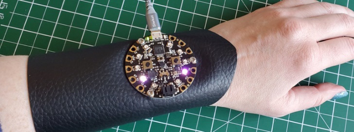
Figure 4.9 – Completed project
Now that we’ve completed this quick prototype, let’s explore the world of flex sensors and make some of our own.
Understanding flex sensors
Because we move in all sorts of ways, a flex sensor can be a great way to track some of that movement. Where do we bend? Elbows, wrists, fingers, toes, ankles, knees, and the waist are a few examples. We can buy flex sensors, that are of various lengths. To get an accurate reading, you need to consider the position and how you can protect the sensor. Be sure it isn’t too delicate a sensor if it is placed somewhere with vigorous bends.
In terms of sensors, you can get a carbon-impregnated conductive rubber cord or a flex sensor/bend sensor, which is like a variable resistor. As it bends, the resistance values change. There are also a variety of linear soft pot ribbon sensors, square force-sensitive resistors, circular soft potentiometers, and round force-sensitive resistors available. We will look at these in more detail in Chapter 5, Working with Sensors: All about inputs!.
By measuring the resistance, we can tell how much bend there is. We can read the sensor by connecting it to a fixed-value resistor, 10kΩ (Ohms), which creates a voltage divider. A voltage divider is a linear circuit that produces the output voltage, which is a fraction of the input voltage. Essentially, it changes a large voltage to a smaller one.
We connect one end of the sensor to power and the other to a pull-down resistor. The fixed-value resistor and the flex sensor are connected to the analog-digital converter (ADC) input of Arduino. This creates a variable voltage output that Arduino reads.
We can use our multimeter to see these changes. Let’s try that now.
Activity 4.3 – using a multimeter to read our flex sensor
Using your multimeter, you can take a resistance reading. I put this flex sensor in a small breadboard because it was easier to read the values that way. The two metal probes at the bottom are too close together to get an accurate reading otherwise. Figure 4.10 shows the sensor flexed with the reading at almost 400 Ohms. A straightened-out sensor has carbon particles very close together, so a value of 0 should be noted when flexed as these particles space out a lot more:
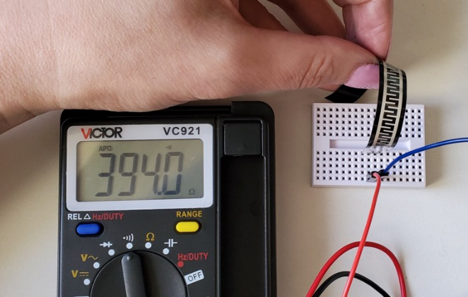
Figure 4.10 – Multimeter readings of the sensor flexed
Now that we’ve looked at traditional flex sensors to understand them, we can build our own! We know we are looking for changing resistance values. Let’s look at how flex/pressure sensors are used in real-world applications. This next section is all about research and innovation.
Research and innovation
Flex sensors are used in some of the wearables that we looked at in Chapter 1, Introduction to the World of Wearables. Their use in sports clothing and medical monitoring devices are some of the most common. Flex sensors, such as the stretchable graphene thermistors researched by Khan, Y., Ostfeld, A. E., Lochner, et al. (2015), which also detail respiration knits and patches that are used for monitoring vital signs.
Human finger tracking was explored in Ponraj, G., & Ren, H. (2018). In their paper, they observed how much human hands are used every day, including in “gesture recognition, robotics, medicine and health care, design and manufacturing, art and entertainment across multiple domains.” Other interesting research is regarding sitting postures and the health issues that may come with them. The system described by Hu, Q., Tang, X., & Tang, W. (2020) uses six flex sensors to create a “novel posture recognition system on an office chair.”
Monitoring neck posture also involves using flex sensors (Guo, Y. R., Zhang, X. C., & An, N., 2019). Two are attached to the neck to warn users about neck posture for better neck health. The research by Hiader, S. A. A., Nasir, A., et al. (2021) focuses on the design and development of low-cost 3D prosthetic hands using flex sensors. Additional work in the field includes developing gloves for communicating sign language, gloves for motorbike drivers to measure hand forces during motorbike riding, and wearable bands for stress detection. Smart garments for monitoring body posture also make use of flex sensors, such as controlled robotic hands for people with disabilities. Smart gloves are also a popular wearable and if you search, you will find inspiring examples and good starting points for your wearable projects!
There is more information on these types of sensors in the paper by Kamara, V. (2019), A Comparative Characterization of Smart Textile Pressure Sensors. 2019 41st Annual International Conference of the IEEE Engineering in Medicine and Biology Society (EMBC).
Please check out the Further reading section for the full references to these papers so that you can explore flex/force sensors in greater depth.
Now that we understand the potential for flex/pressure sensors in real-world applications, let’s make one!
Activity 4.4 – making a flex sensor
Let’s start making a flex sensor. Being able to make components is a good skill to have because, for wearable technology, we can mold and create sensors to fit the curves of the body. We can make them fit smaller or more unique places. Also, when you make a sensor, you know what materials are in it and exactly how it will work:
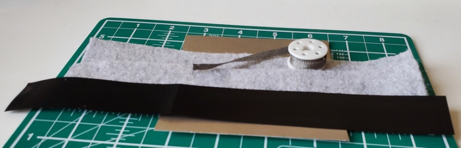
Figure 4.11 – Materials for the flex sensor
The materials (Figure 4.11) that we use for this sensor are as follows:
- Conductive fabric. I’m going to use steel ribbon as it’s already a good size and easy to use. You can also use sticky nylon sheets or other conductive fabric that you have.
- Velostat, which is a resistive plastic. It will change resistance when there is force on it, so we can use it as a force-sensing resistor, or in this case, flex.
- I’m using felt as my fabric base for this flex sensor.
- A sewing needle, clips, thread, and conductive thread.
Once you have collected these materials, measure out the size of the sensor that you want. The main thing you need to remember is the Velostat must cover all of the conductive fabric or conductive steel ribbon.
You’ll need two pieces of felt (or other fabric), one piece of the Velostat that will go in the middle of this sandwich, and two pieces of conductive fabric, or as I’m doing, the steel ribbon. I’ve laid these out as shown in Figure 4.12, with the pieces in place of where they will be once sewn:

Figure 4.12 – Placed materials
I flipped over the end of the steel ribbon (Figure 4.13) to make it easy to sew into the circuit without it unraveling. I sewed it in place with conductive thread. If you’re using a conductive material, you may not need to fold it over, though it does give it additional strength. Balance conserving material with your sensor reliability. Also, be sure to not cause a short within your circuit:

Figure 4.13 – Sewing the edge over
Once your materials are secured in place, layer them like a sandwich. You’ll have a layer of felt, then conductive material (steel ribbon), then Velostat. Then, you’ll have the other conductive material and lastly the other piece of felt or fabric. Figure 4.14 shows how the layers should be created:
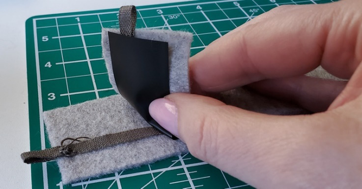
Figure 4.14 – Layering the materials
Once they have been layered, we will sew them together. Just use a simple running stitch all the way around. First, I’ll clip it into place (Figure 4.15), and then start sewing from the top corner.
Important Note
Be sure you don’t pierce the Velostat, and make sure that the two conductive material pieces are not touching each other – this will create a short circuit!
The finished stitching and sensor are shown in Figure 4.15. Notice that the tabs are not touching:
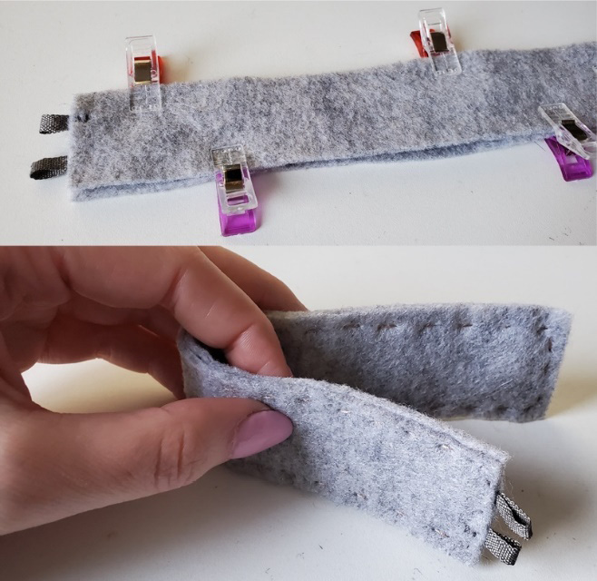
Figure 4.15 – Clips holding the fabric (top) and the completed sewing (bottom)
Once you’ve finished sewing, use your multimeter to measure the circuit when it is pressed, flexed, and bent (Figure 4.16). You are looking for a change in values to indicate there is movement in the sensor:

Figure 4.16 – Checking for changes with a multimeter
Now that we’ve measured our flex sensor and know that it works, let’s connect it to our Circuit Playground board!
Activity 4.5 – connecting your circuit – an LED reaction to flexing
Now that we’ve made a flex sensor, we need to connect it to our Circuit Playground board. There are only two pin-outs on the flex sensor. One will go to power on our board, while the other will connect to an analog pin on the Circuit Playground board – first to the ground and then to a 10K resistor to the ground tab on the board. We made sew pads for the sensor so that we can use croc clips to connect it up and see it all working. Let’s take a closer look – Figure 4.17 is a mapped-out plan for our flex sensor circuit:

Figure 4.17 – Mapping the circuit
Mapping the circuit is a great way to find errors and be sure of our connections before we commit to sewing or soldering!
Don’t Forget
Always choose the board and port you are using from the Tools menu in the Arduino IDE before trying to upload your code!
The circuit mapped on paper will look like the connected version shown in Figure 4.18. One of the tabs on the flex sensor connects to power. The other tab connects to pin 10 and connects a ground wire that has a 10K resistor, completing the ground circuit. In my example, the resistor has been connected to the board using the screws we had earlier:
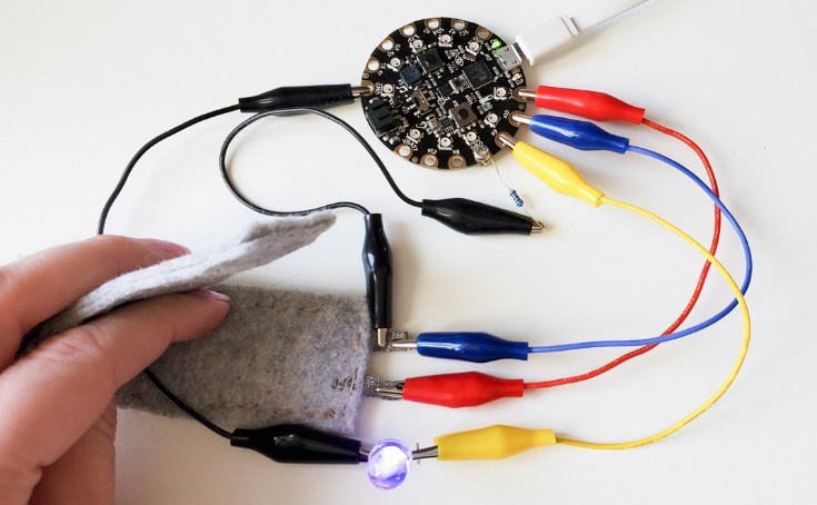
Figure 4.18 – Connected board and flex sensor
Now that the circuit is connected, let’s look at the code. You can watch the video at https://youtu.be/MzdQFUCvan0 to follow along. The code for this can be found at https://github.com/cmoz/Ultimate/blob/main/C4/Activity_4_5.ino.
First, let’s define the pin for the LED. We need to choose a pin that can do a PWM output. This is because we don’t only want an on or off value – we want to see a variation in brightness. On the Circuit Playground Classic board, I’ve chosen pin 9.
Also, define flexPin as an analog input pin. Here, I’ve chosen pin 10. If you are using a different board, be sure to choose a PWM pin for the LED and an analog pin for the sensor. This is because we want a range of values and not limited to 1 or 0.
The Circuit Playground Classic board has the following pins:
- D6, D9, D10, and D11 digital/can be analog inputs
- D3, D6, D9, and D10 digital/can be PWM outputs
Lastly, we have a variable of int type called flexValue. These are used to hold the value of the flex sensor reading:
int ledPin = 9;
int flexPin = 10;
int flexValue;
In the setup() function, we set the LED pin as an output and start Serial communication:
void setup(){
  pinMode(ledPin, OUTPUT);
  Serial.begin(9600);
}
In the loop() function, we start by reading and saving the analog value that we are getting from the flex sensor. We print that value to Serial Monitor to check if it is working correctly. We can open Serial Monitor and read the values as we flex the sensor:
void loop(){
  flexValue = analogRead(flexPin);
  Serial.println(flexValue);
  flexValue = map(flexValue, 700, 900, 0, 255);
  analogWrite(ledPin, flexValue);
  delay(100);
}
There is a new function in the loop() code block. We use map() to map values 0-1023 and 0-255 of pulse width modulation (PWM). This re-maps a number from one range (in this example, the values 0-1023 of the analog input) into a different range (0 to the maximum 255 color value). Here, we are mapping to the max value that we can use with the LED (255) as we want light from the values.
Test your flex sensor and find out what your values are. Test it by using your multimeter, as we’ve done earlier in the chapter. Flex, press, and bend your sensor and write down the lowest and highest values you are getting a reading for. I’ve remapped mine to hold the values 848 to 1015, so I’ve modified that line of code to read as follows:
flexValue = map(flexValue, 848, 1015, 0, 255);
You will need to change these values since your flex sensor is different from mine.
After the map() function, we must write the value from the flex sensor to our ledPin. This will change the LED’s brightness. The code sends the PWM amount to the LED. Finally, we can complete the code with a short delay to see the changes in the LED’s brightness.
Let’s take a closer look at the Arduino IDE. We’ll be using it for more wearables throughout this book, and of course for your wearable technology projects afterward too!
So, let’s go ahead and hook up the Gemma M0 board with a flex sensor and servo motor.
Activity 4.6 – hooking up the Gemma M0 board with a flex sensor and servo motor
This super little board is a great way to start many wearable technology projects. It’s a great choice for circuits that need a discreet board with enough inputs and outputs to make a wearable design interactive.
While we’re here, let’s talk about servo motors. Servo motors are used where there is a need for small, accurate movement or position. They are good for applying low-speed and accurate positions. These motors are used in robotic arms, flight controls, and control systems.
Servo motors are available in different shapes and sizes. For this circuit, we will use a 180-degree servo that is common to many kits. It’s often called a Tower Pro servo motor and weighs 9 g and is 23 x 12 x 29 mm in size. A servo motor has three wires – one for voltage, another for ground, and another for the position setting. The red wire is for power, the black (or brown) wire is for ground, and the yellow wire is the signal wire.
Let’s hook this up with crocodile clips to check our circuit planning. As you already know, the flex sensor has two pins. It’s a resistor, so the pins are interchangeable.
Important Note
Always unplug the circuit board from its power source whenever you are making any changes!
The following diagram shows how to hook everything up. Here, the servo has three wires. Don’t forget that there are two wires going to one pin on the flex sensor – the analog pin, A0 (blue), and GND (black):
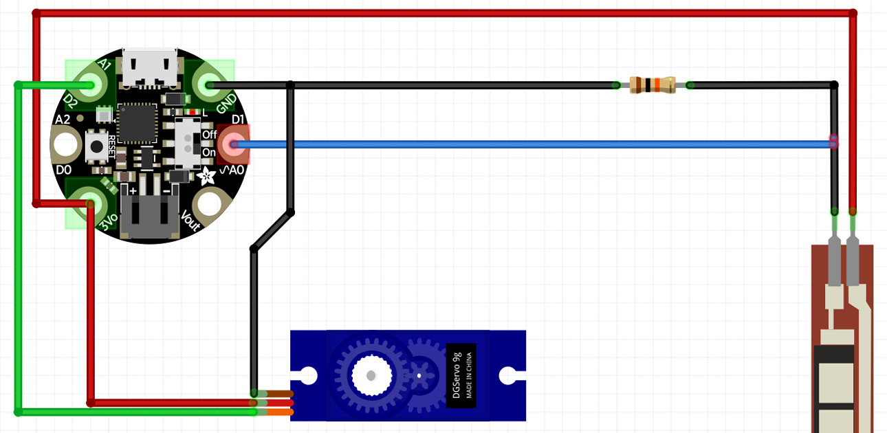
Figure 4.19 – The circuit with the Gemma M0 board, the flex sensor, and the servo motor
Let’s take a closer look. You can use the preceding diagram to follow along. First, let’s hook up the flex sensor:
- Connect one of the pins to ANALOG IN pin A0 on the Gemma M0 board. Connect the same pin, through a 10K ohm resistor (brown, black, orange), to GND.
- Connect the other pin to 3.3V
The servo has a cable with three wires; hook them up as follows:
- Connect the RED wire (power) to 3.3V.
- Connect the YELLOW wire (signal) to pin A1.
- Connect the BLACK wire to ground (GND).
The hook-ups and pins are shown in Figure 4.20 with crocodile clips. These are connecting the flex sensor and servo motor:
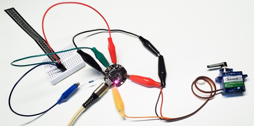
Figure 4.20 – The Gemma M0 board with crocodile clips
The complete code isn’t too complicated for this circuit. It is shown here and available online at https://github.com/cmoz/Ultimate/blob/main/C4/Activity4_6.ino:
#include <Servo.h>
Servo servo1;
int flexpin = A0;
void setup()
{
 Serial.begin(9600);
 servo1.attach(A1);
}
void loop()
{
  int flexposition;
  int servoposition;
  flexposition = analogRead(flexpin);
  servoposition = map(flexposition, 600, 1000, 0, 180);
  servoposition = constrain(servoposition, 0, 180);
  servo1.write(servoposition);
  Serial.print("sensor: ");
  Serial.print(flexposition);
  Serial.print("  servo: ");
  Serial.println(servoposition);
 delay(20);
}
Before we investigate the code in more detail, plug in your Gemma M0 board and upload the code to it. Don’t forget to select your board and port; otherwise, the code won’t upload:

Figure 4.21 – Board and port selection
Let’s look at the code in more detail to understand what’s happening and what variables you may need to change. If you want to follow along, there is a video of this circuit working at https://youtu.be/oO9nMhIsxog.
We start the code by adding our servo library so that we can access servo functions to control it.
Then, we create a servo object called servo1. Each servo object controls one servo. You can have a maximum of 12, but not on this little Gemma M0 board – you’d need to use a board with more I/Os.
We define the analog input pin to measure flex sensor position, which is A0. Remember that if you are using a different board, you may need to change this so that it matches your board. Then, we write our void setup() function, where we set up this sketch. All we are doing is starting the serial monitor and defining that servo1 will read analog data from pin A1.
Moving through to the void loop() function, we create two integer variables to hold the values of the flexposition and servoposition. We set up the value for flexposition to be the analog reading from the flex pin. We servoposition define based on our flex, which we then map to the servo range of 0 to 180 degrees. I’ve mapped my flex sensor so that it has a range of 600 to 1000; yours may differ. Start with a range of 600 to 900 and see how it maps.
Important – bend the flex sensor and make a note of the minimum and maximum values. If you replace the 600 and 900 values in the map() function, you’ll match the flex sensor’s range with the servo’s range:
servoposition = map(flexposition, 600, 900, 0, 180);
map(value, fromLow, fromHigh, toLow, toHigh)
Because every flex sensor, including the ones we’ve made, has different resistance, the range in the map() function may not cover the flex sensor’s output. To tune our program based on the flex, we can use the serial port. This will print out the flex values to the Serial Monitor window.
Because the map() function may return values outside the range, we can use a function called constrain(). This function clips the numbers into a range. So, if the number is outside the range, it makes it the largest or smallest number. However, if it’s within the range, it remains as it was.
Then, we can enable control of the servo and move it into the mapped position.
Note that almost all of the lines for print() are the same, except the last line, which is println(). Without the ln appendix to print, it will put everything on one line. println() will send a carriage return to move to the next line.
After you upload the sketch, turn on Serial Monitor (the magnifying-glass icon to the right of the icon bar). You’ll be able to see the sensor’s values.
Activity 4.7 – using Serial Monitor
Serial Monitor is a great way to look inside our program and find out if it’s working as expected. We had a brief look at this earlier in Activity 4.1 – Hello_Accelerometer, when we looked at what the output was when moving the Circuit Playground board. There are other uses for Serial Monitor and if we add Serial.println("some text"); to our code, we can start to understand which function/method/statement of the code is being executed.
You can use USB-serial communication and Serial Monitor in the Arduino software to view what sort of values you’re getting in. To use the serial monitor, we need to initialize it in our code using Serial.begin(speed). Include this code in your setup() function. Set the speed of communication by writing the value in parenthesis. A standard rate that’s used in examples is 9600 baud. Serial.println(val) sends the value followed by a new line. Using Serial.print() will keep the responses on the same line.
When you open Serial Monitor, you should see the values and responses from Arduino. There is a drop-down menu for the rates of communication, or baud rate, that you can select. The baud rate is the rate of communication that the computer and Arduino use to talk to each other. Check if the baud rate of your serial monitor matches the value you set in the Serial.begin() function. You’ll quickly find out if they don’t match because the output will not be readable!
Let’s look at Serial Monitor as we flex and bend our sensor:

Figure 4.22 – Serial Monitor output
If everything is fine, you should see a change in resistance as you bend the flex sensor, as shown in the preceding screenshot.
The following is an example of how we could display information:
Serial.print("sensor = ");
Serial.print(sensorValue);
Serial.print("	 output  = ");
Serial.print(outputValue);
The preceding code will result in the following output:
Sensor = 250 output = 33
places a tab space between the output.
Serial Monitor is a good way to check that your sensors are working how you expect. In the wearables you make, you’ll be using this feature of the Arduino IDE often. We can test our circuit by flexing it and reading the values on the screen. This will help us make sure it works as we expect.
Now that we’ve seen the output on Serial Monitor and that the code is working, we can decide how and where we might like to incorporate this circuit.
Troubleshooting
Is your circuit working fine? Does your servo move when the sensor you made is pressed and flexed? If not, you may want to investigate these things first. Don’t forget that there are many great places online for resources to help you on your journey. For more information about the servo library that we used in our code, you can visit https://www.arduino.cc/reference/en/libraries/servo/. For a clear hookup guide, you can visit https://docs.arduino.cc/learn/electronics/servo-motors.
If your servo is not twisting, I would first look at the connections. Even with the colored wires, you may have put it in backward. Check your connections to see that power is going to the power pin on the Gemma M0 board. If the servo is not moving as you are expecting it to, remember that this sensor works best in one direction, or sometimes with pressure. Try flexing it in different directions to see if your flex sensor responds. If you find that your servo doesn’t move very far, remember that we looked at modifying the map() function in the code. You need to modify the range of values according to what your sensor is outputting. Lastly, make sure the pin you are using (you may have connected it to a different board, for example) has analog in and PWM out for the LED. Be sure to change these pin numbers in the code too!
I hope that helps – if not, search online; there are usually many people who will have had the same issue as you.
The Arduino IDE
We’ve used the Arduino IDE for a couple of projects, so the interface should be familiar to you. In this section, I want to cover a few basics of programming and the interface.
This section is for beginners so that they feel more comfortable with using Arduino. If you are a seasoned programmer, you may want to jump ahead to hooking up the Gemma M0 board.
Let’s take a brief tour of a few of the terms and what they are:
- Functions
- Variables
- Other tips/syntax
We’ll start by looking at functions, which we covered briefly earlier in this book.
Functions
Functions are important for segmenting code into modular pieces. These perform a defined task and then return to where that code was called from. It’s useful if there are a series of steps that we want to repeat. An example is the digitalWrite() function, which we can use to write a HIGH or LOW value to a digital pin. We can write our own functions, but digitalWrite() is one that is prewritten in Arduino for us.
Variables
A variable is used to store a value. Think of it as the container we use. It can hold different types of values, depending on what we need to use in our program. We have already used integers, whole numbers, and float values for decimal places. We can also use strings for strings of text. To use a variable, we must declare it. We can also use characters and Booleans as variables.
To declare a variable, we must give it a type, a name, and a value. We can declare variables without giving them a value, but we can’t give a value to something we have not declared yet. This will always give us an error message. Earlier, we declared three variables of the float type with three names – X, Y, and Z:
float X, Y, Z;
We could have declared it this way for clarity:
float X;
float Y;
float Z;
Because they are all the same type, we can declare them together. When we were using the variable, we assigned it a value:
X = CircuitPlayground.motionX();
In this example, we are assigning the X float variable a value of the x movement of the board. The variable name must be the same every time you use it in your sketch; otherwise, it won’t be recognized.
Variable Naming Conventions
There are a few conventions to follow when naming a variable: it can’t start with a number, it can’t have any spaces in it, and it can’t be a word that the Arduino language already uses for another purpose (for example, we can’t use delay because it’s reserved by the Arduino language). If your code does not compile or throws an error, often, variables are the place to look to troubleshoot the issue.
Also, it’s good practice to name your variables something that indicates their purpose, as shown here:
int randomValR = random(255);
We named this integer variable randomValR because it holds the randomly generated value for the red portion of the code.
Other
We’ve already looked at the structure of the Arduino sketch, which has a setup() and a loop() function. There are also control structures we will learn along the way. We saw a for loop and an if statement too.
A for() loop repeats a block of statements enclosed in curly braces. We used a variable to increment and terminate the loop. A for() loop is useful for repeating code.
The if statement checks a condition and if the condition is true, it will run the code. Also, curly braces signify when we start and end a block of code.
Lastly, there is always more than one way to write code. Don’t worry if you do it differently than someone else. All you have to do is look online at examples and you will see that there is always a selection of people doing the same thing, but they program it differently. It’s more important to try your circuits and your code. You can always go back to it later to tidy it up or edit it.
Summary
This has been a very busy chapter where you have been making circuits, programming them, and learning about new sensors and servos. We started by using the Circuit Playground board to explore one of the many sensors: an accelerometer. We used this onboard sensor with NeoPixels to track movement. This was a great way to see firsthand the fun we can have with NeoPixels! Using the sensors on the Circuit Playground board is a great way to add interactivity to future projects. It demonstrates that we can use the sensors onboard to test code and circuits quickly.
Then, we jumped straight into understanding flex sensors. We looked at using an off-the-shelf component, but also how we can build our own. Being able to build sensors opens a whole new world for your wearables. You can start to plan your circuits and make the sensor fit easily with the body part you desire. We also used a multimeter to help us take readings from the sensor to make sure it was working.
Lastly, we learned how to hook up and incorporate our handmade flex sensor with a servo motor for output. This involved you also learning about Serial Monitor, which can be a useful tool for finding errors. We looked at using Serial Monitor to read the values from the flex sensor and servo motor to ensure it was working as we expected. We managed to connect our components using the Gemma M0 board because it’s small and great for wearables. It has enough power to use both components to add interactivity to our wearable technology.
Hopefully, you’ve found this a useful chapter to keep your wearable journey full of curiosity and explorations. Making a component is great fun and I hope you’ve started to plan how you would integrate these two components into a wearable item.
Will you bend your finger so that it moves like a flower or butterfly? Does the bending control a little flag or message? Does it connect to your knee and when you bend, the servo hits a small drum for noise?
In the next chapter, we take our explorations further by learning about the sensors that can collect data from our environment. We’ll look at how we can use these sensors, what sensors there are, whether we can make them ourselves, and how to do some basic hook-ups into our wearable designs. It’s all about input!
Further reading
To learn more about the topics that were covered in this chapter, take a look at the following resources:
Khan, Y., Ostfeld, A. E., Lochner, C. M., Pierre, A., & Arias, A. C. (2015). Monitoring of Vital Signs with Flexible and Wearable Medical Devices. Advanced Materials, 28(22), n/a--n/a. Available at https://doi.org/10.1002/ADMA.201504366.
Ponraj, G., & Ren, H. (2018). Sensor fusion of leap motion controller and flex sensors using Kalman filter for human finger tracking. IEEE Sensors Journal, 18(5), 2042-2049.
Hu, Q., Tang, X., & Tang, W. (2020). A smart chair sitting posture recognition system using flex sensors and FPGA implemented artificial neural network. IEEE Sensors Journal, 20(14), 8007-8016.
Guo, Y. R., Zhang, X. C., & An, N. (2019, August). Monitoring neck posture with flex sensors. In 2019 9th International Conference on Information Science and Technology (ICIST) (pp. 459-463). IEEE.
Hiader, S. A. A., Nasir, A., Ameen, M., Raza, A., Waleed, A., & Ali, Z. (2021, November). Design and Development of Low Cost, Wireless Controlled, 3D Prosthetic Hand using Flex Sensors. In 2021 International Conference on Innovative Computing (ICIC) (pp. 1-6). IEEE.
Zubair, M., Yoon, C., Kim, H., Kim, J., & Kim, J. (2015). Smart Wearable Band for Stress Detection. 2015 5th International Conference on IT Convergence and Security (ICITCS). Available at https://doi.org/10.1109/ICITCS.2015.7293017.
Abro, Z. A., Yi-Fan, Z., Nan-Liang, C., Cheng-Yu, H., Lakho, R. A., & Halepoto, H. (2019). A novel flex sensor-based flexible smart garment for monitoring body postures. Journal of Industrial Textiles, 49(2), 262-274.
Latif, S., Javed, J., Ghafoor, M., Moazzam, M., & Khan, A. A. (2019, August). Design and development of muscle and flex sensor controlled robotic hand for disabled persons. In 2019 International Conference on Applied and Engineering Mathematics (ICAEM) (pp. 1-6). IEEE.
Review questions and exercises
Answer the following questions and complete the following exercises to test your knowledge of this chapter:
- How do we know our flex sensor is working?
- What happens if you name my variable something that is not allowed?
- Why do we use Serial Monitor?
- Why did we need to choose a PWM pin for the LED?
- Can you complete the circuits created in this chapter? Add them to a part of the body, sew them into a design, or plan where you may want to incorporate them.
- Spend some time planning a flex sensor for a different part of the body. What do you need to consider if you are planning for a finger? For the knee? How will these sensors differ? Be aware of the size differences and the pressure or flex on different parts of the body. The knee will need to track a wider movement, but the finger will involve smaller, more precise movements.