Specification of the 625/50 longitudinal timecode waveform
| Rise and fall times: |
50 (+15, -10) ±s, measured between the 10% and 90% amplitude points of the waveform |
| Shape of pulse edges |
sin2 |
| Maximum overshoot, undershoot and tilt |
5% of peak-to-peak amplitude |
| Nominal clock period |
500 μs |
| Maximum timing error of any clock period |
±2.5 μs |
| Maximum timing error of 1 transition |
±2.5 μs |
Specification of the 625/50 vertical interval timecode waveform
| Pulse amplitude, logic 0 |
0-25 mV |
| Pulse amplitude, logic 1 |
550 ± 50 mV wrt blanking level |
| Clock period |
0.556 jus approximately. |
|
The bit rate is specified as fh x 115 ±2%. |
|
Note: the bit rate is fh x 116 + 200 bits/s (where fh is the line frequency) |
| Rise and fall times of transitions |
200 ± 50 ns |
| Maximum overshoot or undershoot |
5% of peak-to-peak amplitude |

Figure A2.1 LTC waveform specification. Courtesy of SMPTE Journal.
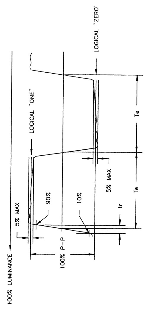
Figure A2.2 VITC waveform specification. Courtesy of SMPTE Journal.
Specification of the 525/60 longitudinal timecode waveform
| Rise and fall times |
25 ±5 μs, measured between the 10% and 90% amplitude points of the waveform |
| Maximum overshoot, undershoot and tilt |
2% |
| Clock period |
416.7 μs |
| Maximum timing error of any clock period |
± 4.2 μs |
| Maximum timing error of 1 transition |
± 2.1 μs |
Specification of the 525/60 vertical interval timecode waveform
| Pulse amplitude, logic 0 |
0-10 IRE |
| Pulse amplitude, logic 1 |
70-90 IRE |
| Clock period |
0.552 μs approximately |
|
The bit rate is specified as fh x 115 ± 2% |
|
(where fh is the line frequency) |
| Rise and fall times of transitions |
200 ± 50 ns |
| Maximum overshoot or undershoot |
5% of peak-to-peak amplitude |
..................Content has been hidden....................
You can't read the all page of ebook, please click
here login for view all page.