
2. Finding Your Way Around the Interface
In This Chapter
• What is the ribbon?
• When would I use contextual tabs?
• What’s in a contextual menu?
• What is in the drawing window?
• How can I work with shapes?
• Can I use keyboard shortcuts?
If you have ever been lost and consulted a map to get your bearings, you already understand the concept of this chapter. This chapter shows you where things are located, and you become aware of various menus and tools that might otherwise escape your attention. Notice how things are referred to in this chapter because that makes it easier to follow the steps and recognize these features throughout this book.
You may already know or understand some of the features presented here; just skim through to make sure you haven’t missed any critical information. The same as with a map, you can come back to this chapter occasionally to get your bearings, if you need to.
The Ribbon
Microsoft introduced the Fluent User Interface (Fluent UI) with Office 2007, and it has been a feature in Visio since 2010. Undeniably, the horizontal ribbon of tabs is the most noticeable feature of the Fluent UI, which also provides a backstage area, a status bar, and a Quick Access toolbar (see Figure 2.1).
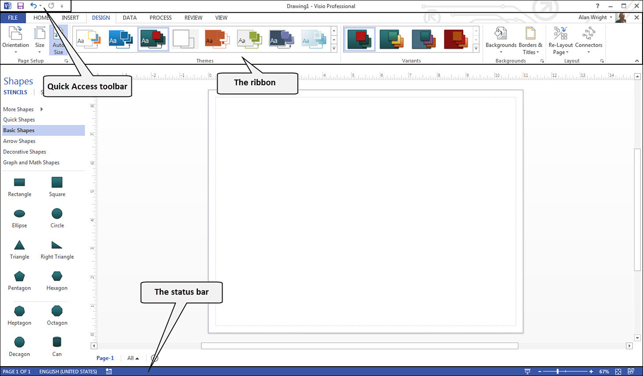
FIGURE 2.1 Visio 2013 includes the standard Office interface elements such as the ribbon, status bar, and the Quick Access toolbar.
If you have not used this type of interface before, you may be initially perplexed by the way menus are grouped into tabs. This is an efficient and intuitive way to access the many tools included in Visio.
Embrace the Tab
In Visio 2013, notice the tabs for File, Home, Insert, Design, Review, and View. Professional also provides you with Data and Process tabs.
Tabs are tools that have been grouped together based on tasks; tools are grouped together even further on the tab itself. When you want to insert a picture or text, you find those tools on the Insert tab. When you change the appearance of a drawing, you find common tools for this task on the Design tab, and so on.
Tabs contain many straightforward tools and quite a few unlabeled controls that reveal additional options that you may not need to see as often. Figure 2.2 shows some of the types of controls available on a tab:
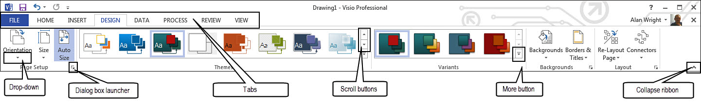
FIGURE 2.2 Tabs present a streamlined array of tools to suit a task and still provide many ways to access additional tools as needed.
• Drop-down arrows indicate the presence of a menu with additional tools. Selecting this expands down to reveal the drop-down menu.
• Dialog box launchers open a small window referred to as a dialog box. This contains additional options and tools.
• Tabs allow you to quickly jump from one tool set to another based on the task at hand.
• Scroll buttons are used with galleries, and they allow you to browse right from the tab.
• More buttons expand a gallery and provide access to additional menus.
• Collapse ribbon hides the ribbon from view, allowing for more screen to be used in the drawing window. Selecting a tab reveals its contents temporarily.
Contextual Tabs
Contextual tabs refer to tabs that appear only as needed. They contain tools that are unique and are needed only when working with special templates or when special tool sets are used. Often these appear simply because of a shape that has been selected. Figure 2.3 shows the Picture Tools Format tab. This tab is visible only if an image file is selected.

Following are contextual tool tabs you may encounter:
• Picture Tools
• Ink Tools
• Container Tools
• ShapeSheet Tools
Template Tabs
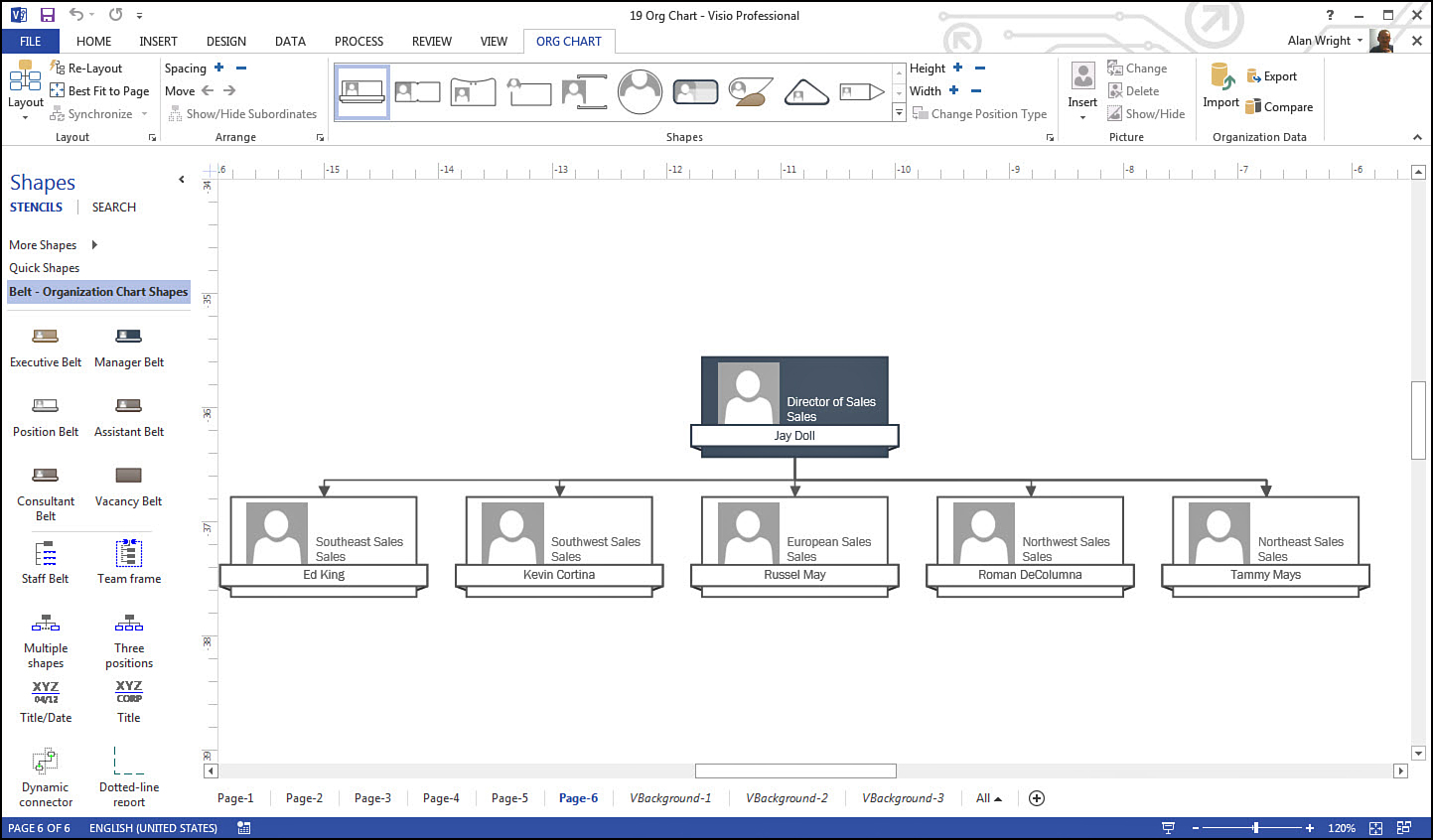
Many templates are so unique that they have special tools grouped into their very own tab. Open one of these templates and the tab appears automatically. Figure 2.4 shows the Org Chart tab, which contains unique buttons related to org chart shapes, spacing, size, and contents.
Following are some of the template-specific tabs you may see:
• Brainstorming
• Cross-functional Flowchart
• Plan
• Org Chart
• Gantt Chart
• Web Site Map
Customizing the Ribbon
As you can see, the ribbon is practical. Imagine trying to find space to work if all the buttons and tools were always visible. It is possible to create custom tabs and tool groups where you can collect selected tools all in one place.
Customizing the ribbon is done from the Visio Options dialog box, shown in Figure 2.5. Notice that there are two lists—the first shows commands that exist and the second shows locations on tabs where commands are or can be located.
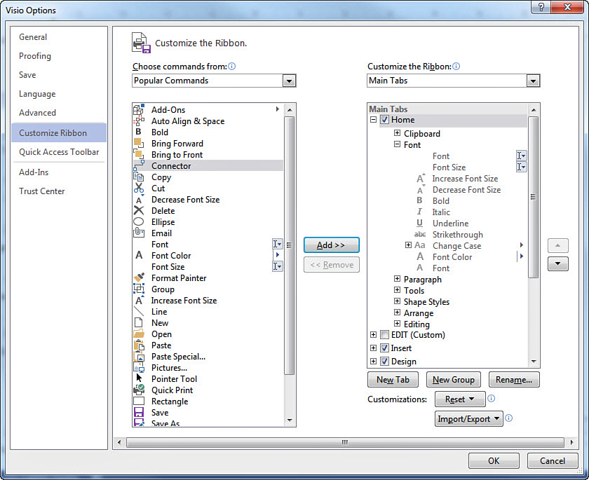
The first list, Choose Commands From, defaults to the Popular Commands option. You can select in the drop-down list from a few other options to refine the list of commands shown. For example, All Commands lists every command Visio includes, whereas Tool Tabs lists only commands currently located on the four contextual tool tabs.
The second list, Customize the Ribbon, enables you to show the All, Main, or Tool tabs. Based on the selection, you can expand a tool group using the plus sign (+) to see the tools located in the group or collapse a tool group using the minus sign (−). Check boxes enable you to hide or make visible individual tabs.
Selecting commands from either the Choose Commands From or Customize the Ribbon lists allows you to use the Add and Remove buttons in the middle to change the contents of custom tabs and custom tool groups. You can also rename tabs, add new groups and tabs, or reset the commands and tabs to their original configuration.
To customize the ribbon and add a couple of commands, follow these steps:
1. Select the File tab and then select Options at the bottom of the left-side vertical menu.
2. Select Customize Ribbon from the vertical list of tabs on the left.
3. Below the list to the right, select the New Tab button. This adds a new tab and a new tool group to the list of tabs.
4. Select the new tab you just created and then select the Rename button. Type in the display name for your tab using all uppercase letters in the Rename dialog box that pops up so that your tab name will match the default tab name uppercase formatting. Click OK.
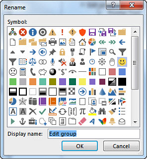
5. Select your new tool group and then select the Rename button again. In the Rename dialog box shown in Figure 2.6, type in a display name for your group and click OK. (You can see symbols listed here, but they appear only when you rename a command, at which time you can assign a symbol to replace the displayed icon.)
6. Using Popular Commands to display commands in the left-side list, select Pointer Tool and then select the Add button. The Pointer tool is now listed in the new group you just created.
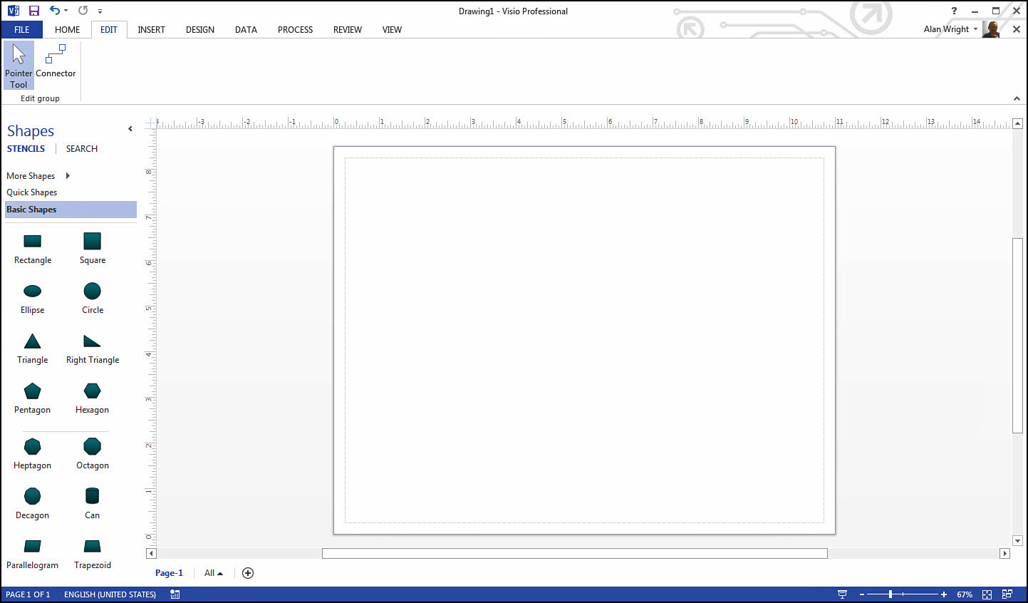
7. Select the Connector command from the list of popular commands, and select Add to add it to your custom group. Figure 2.7 shows the new tab named Edit and the new group named Edit Group. Both have (Custom) following the name to alert you to the tab being customized, but it does not appear on the actual tab.

8. Click OK on the Visio Options dialog box to close it and apply the changes you have made. Visio pauses as it updates, and then your tab appears as shown in Figure 2.8.
Where Did That Command Go?
As Visio has evolved, some commands have dropped from usage, or they have moved. You might get frustrated when you’re unable to find a command that you know used to be in a certain place. Use the Visio Options dialog box to help you locate those commands. To open this, select the File tab, select Options, then select Customize Ribbon.
To locate a command, select All Commands from the drop-down list located under Choose Commands From, and scroll through the alphabetically organized list. You can hover over commands in this list to see where they are located on the tabs, as shown in Figure 2.9. In this image, Bold is shown in the All Commands list as being located on the Home tab, in the Font tool group. The list of the Home tab contents off to the right verifies this.
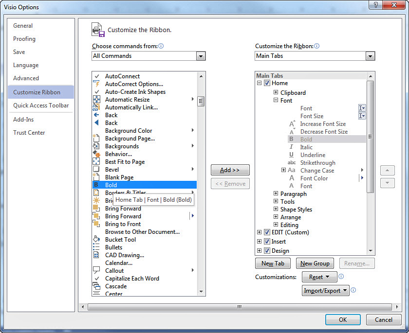
FIGURE 2.9 Find commands using the All Commands list from the Customize Ribbon tab of Visio Options.
In some cases a list is not used on any tab. Figure 2.10 shows how you can also select the Commands Not in the Ribbon to reveal commands that are not located directly on any tab. Notice in this figure that the All Caps command has been found and added to a new custom group.
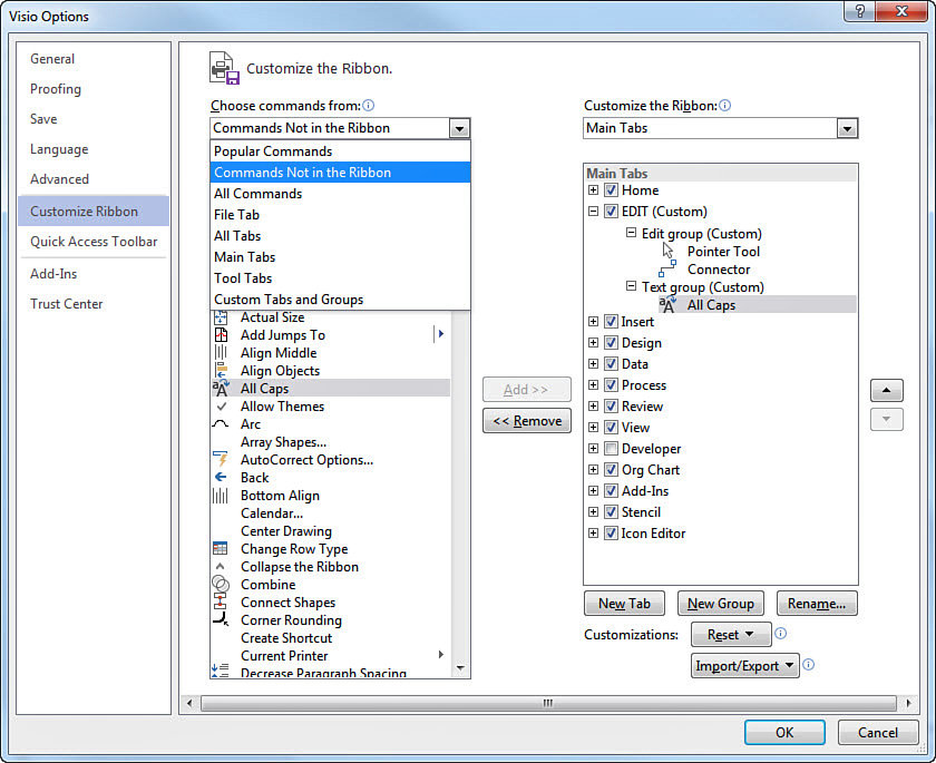
FIGURE 2.10 Checking the list Commands Not in the Ribbon may be useful when trying to locate commands that seem to be missing.
Important Features of the Visio Application
Besides the ribbon, you should know a few other tools when you’re working with Visio that are part of the Fluent UI, which is used across the various Microsoft Office applications.
The Quick Access Toolbar
The Quick Access toolbar allows you to place commands that will always be visible in the upper-left corner of the Visio window (see Figure 2.1). Basic commands are located here by default to save, undo, and redo actions. You can also customize the toolbar by clicking the More button, which reveals the drop-down list shown in Figure 2.11.
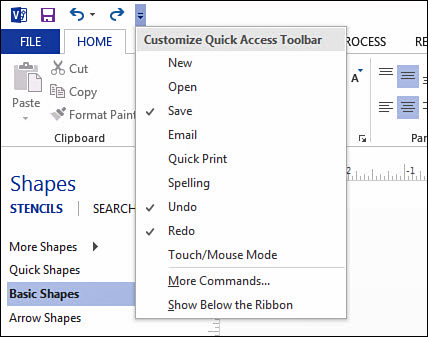
FIGURE 2.11 You can customize the Quick Access toolbar to keep the commands you use often always visible.
If you select More Commands from this list, it enables you to pick specific commands from the Visio Options dialog box similar to the way you found and added commands to tabs in the previous section.
Context Menus
Context menus are sometimes called right-click menus, and they are used the same way in all Microsoft products. They provide basic functions that allow you to cut, copy, and paste, as well as tools to format text and perform editing. In Visio, context menus are valuable tools when working with shapes and text. Some shapes display hidden abilities when examined using the context menu. Figure 2.12 shows the results of right-clicking a door on a floor plan. In the context menu, notice this shape can reverse its orientation with a simple click.
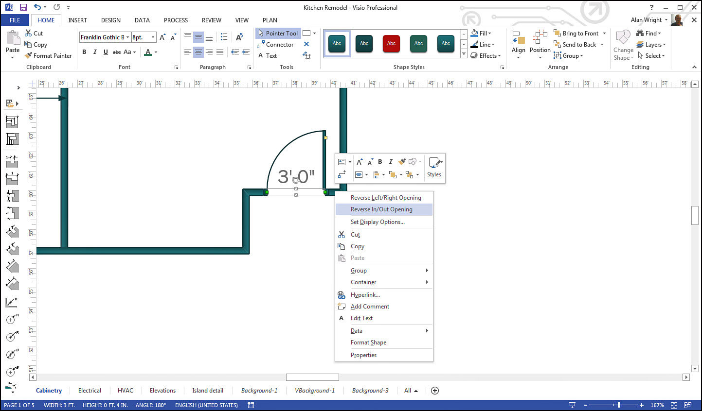
FIGURE 2.12 Context menus provide valuable tools that may be unique to a particular shape like this door shape.
The Backstage
Of all the tabs, the File tab is truly distinctive with its dark blue color, meant to emphasize its uniqueness. Unlike other tabs, this tab takes you behind your drawing to the Backstage area, where you can open additional drawings, create new drawings, save your work, print, share, and export drawings. It also provides access to settings for the Visio application.
Shown in Figure 2.13, the Backstage area does not display the other horizontal ribbon tabs; instead, a vertical list of tabs is found off to the left. To return to where you last were, select the large arrow pointing off to the left at the top of this vertical list.
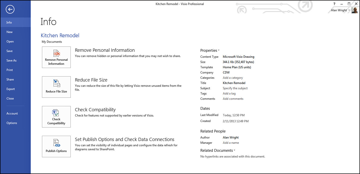
If you select the File tab while working on a drawing, it opens to the Info tab. Here you see document properties related to the drawing you are working on, such as size and date information. When you first open Visio, you are brought to a different part of the Backstage area, allowing you to choose from recent drawings or start a new template.
In this book, you revisit this Backstage area often as you learn about the purpose and content of the different tabs.
The Status Bar
Shown in Figure 2.1, the status bar occupies the bottom horizontal strip of the Visio window. As indicated by the name, it provides status information regarding the drawing that is currently open, revealing the page you are on, language settings, and zoom settings. When a shape is selected, information related to the size of the shape is displayed on the status bar. You occasionally see status messages and progress bars displayed in the middle of the status bar related to file tasks like saving and printing. Use your mouse pointer to hover over items on the status bar to reveal additional information when in doubt.
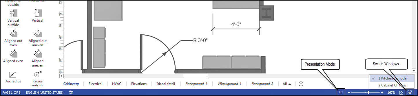
Figure 2.14 points out a couple of buttons located in the status bar that are worth mentioning. To the left of the zoom controls is the Presentation Mode button. This displays your drawing at full screen and allows you to scroll through the pages much like you would in a PowerPoint presentation. Press Esc to return to the normal Visio window. The second button is the Switch Windows button. Select it to see currently open drawings and select a drawing to jump to it.
A Look at the Drawing Window
You have looked above, below, and even behind it; now take a look at the heart of Visio; the drawing window. The drawing window includes all the space between the ribbon and the status bar. Besides the actual page area used for the drawing are a few elements that are usually present when you use the drawing window; these can be hidden if you prefer. Figure 2.15 shows the drawing window with some of these additional elements present, such as task panes.
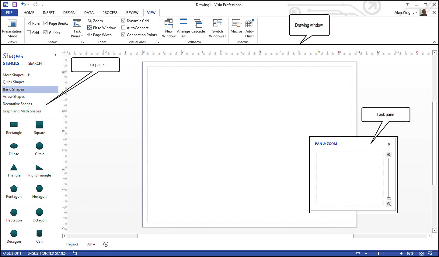
Task Panes
There are a few task panes that you use when working in Visio. Task panes are basically small moveable windows. They can be docked to the side of a drawing window, like the Shape task pane shown in Figure 2.15, or they can float like the Pan & Zoom task pane in the same image. You use task panes often when working with Visio.
→ To learn more about task panes, see page 53.
Rulers and Grids
You can use rulers around the drawing window, and you can add grids to assist you in placing shapes. Figure 2.15 shows rulers along the top edge of the drawing window and to the left of the drawing area. Notice in this image that rulers and gridlines can be displayed or hidden by selecting their check boxes located on the View tab and in the Show tool group.
Manipulating Shapes
A foundation of any Visio drawing is the shape. A few chapters in this book are dedicated to shapes and how you can work effectively with them. It is important to understand some basic characteristics of shapes and how to interact with them using their control handles, sometimes called control points.
Imagine moving a big trunk or suitcase that has handles in the wrong place. Shapes have plenty of control handles that are designed to be used in diverse situations. You look at the basic types of handles here. You can click and drag a handle using the Pointer tool, which is the default pointer when working with Visio. Later in the book, as you see how to use these handles, you know how to find them.
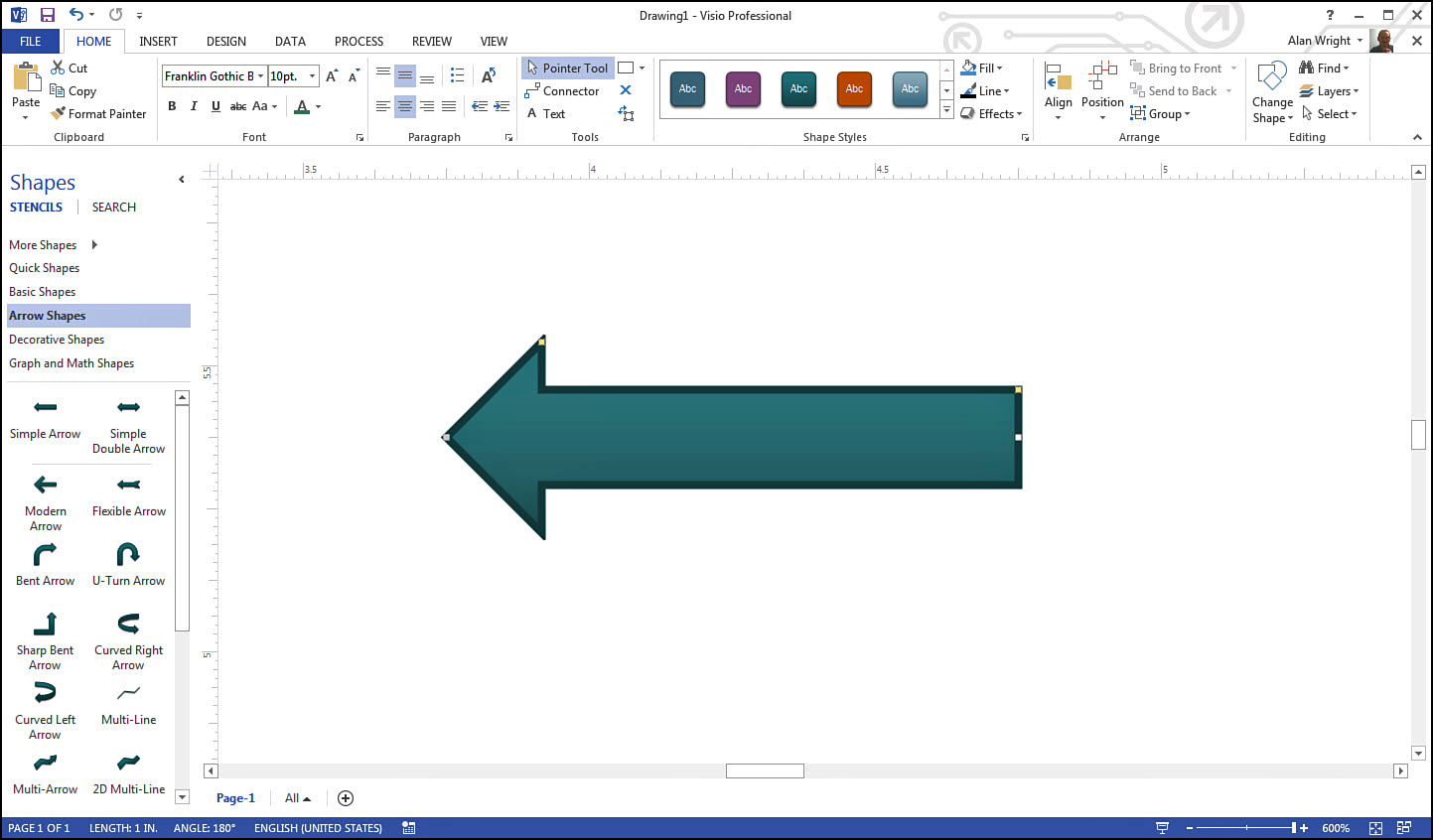
1D Shape Handles
Shapes that are considered one dimensional (1D) include arrows, lines, and connectors. When you select a 1D shape, you see two control handles or points that allow you to position the endpoints themselves. You may see additional yellow control handles that allow you to change additional characteristics.
Figure 12.16 shows an arrow shape, and the two endpoints can be seen. A yellow control handle is located at the top corner of the arrowhead, and dragging this allows you to change the length of the arrowhead itself. The second yellow control handle allows you to widen or narrow the entire arrow shape. All the control handles work around a one-dimensional axis.
2D Shape Handles
Shapes that are considered two dimensional (2D) have more control handles, allowing resizing to be done in more than one direction. Think of 1D shapes as having length, while 2D shapes cover area. The box in Figure 2.17 shows a 2D shape with eight control handles around its perimeter and another control handle for rotating the shape.
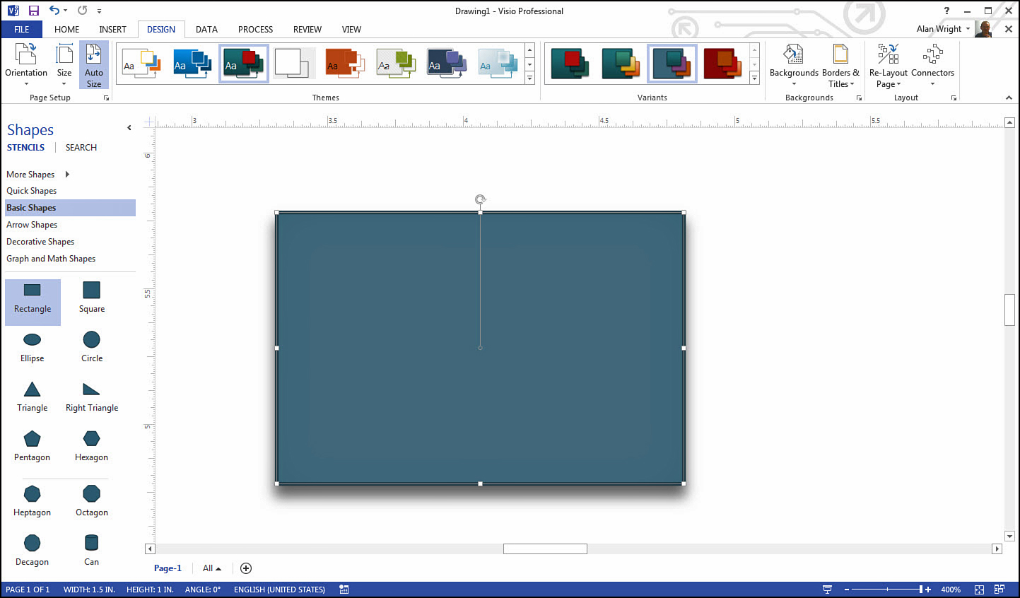
Grab a control handle at a corner, and you can resize in two directions at once. Using midpoint handles you can change the size in one direction. Rotate handles are used to rotate shapes by clicking the circular control handle and then dragging to rotate the shape. You can control the sensitivity of the rotation by how near your cursor is to the shape.
Vertex Handles
Control handles can serve more than one purpose, depending on the tool you select. As you’ve seen in previous examples, the Pointer tool affects basic resizing when you select and drag a control handle. Change the tool on the Home tab to a line shape tool, as shown in Figure 2.18, and then you can change how a control handle responds when dragging it. Vertex handles appear as small blue dots, and the cursor changes to a four-headed arrow when you hover over a vertex handle. A vertex refers to the point where two or more line segments meet.
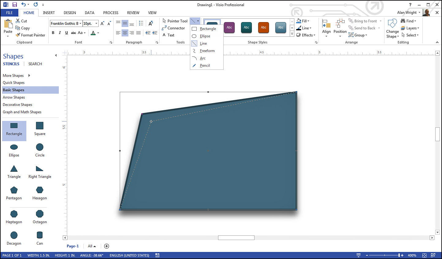
Select a corner using the Line tool, and the vertex handle at the corner allows you to reposition just that corner, resulting in the shape in Figure 2.18. Select the Pencil tool; grab a midpoint between two vertex handles, and pull the side of a shape into an arc. Freeform and arc tools also turn control handles into vertex handles. Experiment with these tools to see how you can use vertex handles in your shapes. Remember that you can always undo actions when you don’t like the results.
Eccentricity Handles
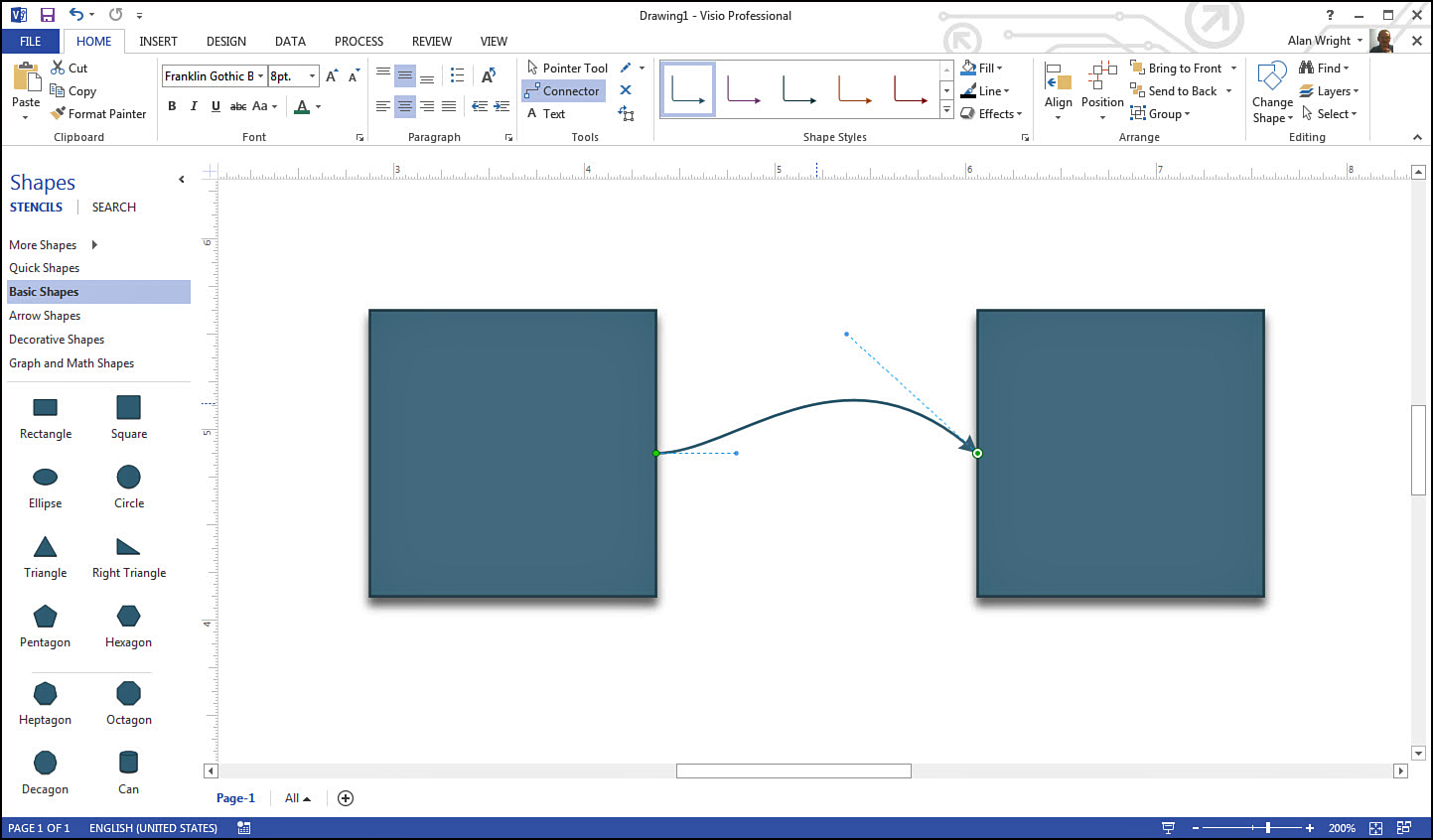
When working with arcs or curved lines, you may see control handles called eccentricity handles. These are used to adjust the severity of an arc and are used when curved connectors have been selected. Figure 2.19 shows a curved connector between two shapes. The two endpoints are easy to see, and extending from those endpoints are two dashed lines ending in eccentricity handles. Pulling and positioning these handles enable you to fine-tune the appearance of the curves seen in the line.
Get Around Using Your Keyboard
This is a section you should return to occasionally as you get comfortable working with Visio. Power users often rely on their keyboard to work faster by opening dialog boxes or activating commands without having to switch tabs or navigate menus with their mouse. As you continue through this book, you will see references to basic keyboard shortcuts that are especially worth knowing and using. Table 2.1 presents a list of the most commonly used keyboard shortcuts. As shown in Figure 2.20, you can often hover over a command on a tab with your mouse pointer to reveal a ToolTip that indicates what the keyboard shortcut might be.
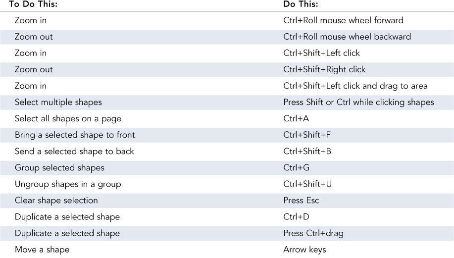
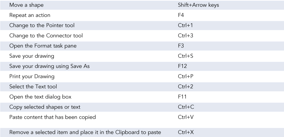
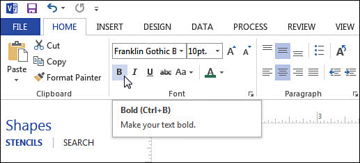
FIGURE 2.20 Hover your mouse pointer over a command to see if there is a keyboard shortcut. Bold text effect can be applied to text by pressing the keys Ctrl+B according to this ToolTip.
Some may not seem as useful and are appreciated only with time. Keyboard shortcuts truly become effective when they become second nature and you can use them without thinking about it. Don’t try to learn them all, and don’t feel bad if it takes you time to remember some of these. Many individuals start by using sticky notes around their computer display to refer to, and this may help you, too. Try each shortcut out as you read through the table and pick a handful to master; then return later to see if others might be useful.
 Note
Note
Another handy way to see keyboard shortcuts within Visio is to press F10. You will see letters and numbers that appear next to tabs and commands. Pressing these letters or numbers will activate that tab or command. This only works while the letters or numbers are visible. Use F10 to turn this off and on as needed.