Radio-Interface Architecture
Abstract
This chapter described the overall NR architecture. DIfferent alternatives for connecting the NR RAN to the core netwrok (EPC or 5GCN) are discussed. The overall protocol structure and the different channel types are also outlined.
Keywords
5GCN; EPC; architecture; dual connectivity; gNB; RAN; user plane; control plane; protocol architecture; paging
This chapter contains a brief overview of the overall architecture of an NR radio-access network and the associated core network, followed by descriptions of the radio-access network user-plane and control-plane protocols.
6.1 Overall System Architecture
In parallel to the work on the NR (New Radio) radio-access technology in 3GPP, the overall system architectures of both the Radio-Access Network (RAN) and the Core Network (CN) were revisited, including the split of functionality between the two networks.
The RAN is responsible for all radio-related functionality of the overall network including, for example, scheduling, radio-resource handling, retransmission protocols, coding, and various multi-antenna schemes. These functions will be discussed in detail in the subsequent chapters.
The 5G core network is responsible for functions not related to the radio access but needed for providing a complete network. This includes, for example, authentication, charging functionality, and setup of end-to-end connections. Handling these functions separately, instead of integrating them into the RAN, is beneficial as it allows for several radio-access technologies to be served by the same core network.
However, it is possible to connect the NR radio-access network also to the legacy LTE (Long-Term Evolution) core network known as the Evolved Packet Core (EPC). In fact, this is the case when operating NR in non-standalone mode, where LTE and EPC handle functionality like connection set-up and paging. Later releases will introduce standalone operation with NR connecting to the 5G core, as well as LTE connecting to the 5G core. Thus, the LTE and NR radio-access schemes and their corresponding core networks are closely related, unlike the transition from 3G to 4G where the 4G LTE radio-access technology cannot connect to a 3G core network.
Although this book focuses on the NR radio access, a brief overview of the 5G core network, as well as how it connects to the RAN, is useful as a background.
6.1.1 5G Core Network
The 5G core network builds upon the EPC with three new areas of enhancement compared to EPC: service-based architecture, support for network slicing, and control-plane/user-plane split.
A service-based architecture is the basis for the 5G core. This means that the specification focuses on the services and functionalities provided by the core network, rather than nodes as such. This is natural as the core network today is already often highly virtualized with the core network functionality running on generic computer hardware.
Network slicing is a term commonly seen in the context of 5G. A network slice is a logical network serving a certain business or customer need and consists of the necessary functions from the service-based architecture configured together. For example, one network slice can be set up to support mobile broadband applications with full mobility support, similar to what is provided by LTE, and another slice can be set up to support a specific non-mobile, latency-critical industry-automation application. These slices will all run on the same underlying physical core and radio networks, but, from the end-user application perspective, they appear as independent networks. In many aspects it is similar to configuring multiple virtual computers on the same physical computer. Edge computing, where parts of the end-user application run close to the core network edge to provide low latency, can also be part of such a network slice.
Control-plane/user-plane split is emphasized in the 5G core network architecture, including independent scaling of the capacity of the two. For example, if more control plane capacity is need, it should be straightforward to add it without affecting the user-plane of the network.
On a high level, the 5G core can be illustrated as shown in Fig. 6.1. The figure uses a service-based representation, where the services and functionalities are in focus. In the specifications there is also an alternative, reference-point description, focusing on the point-to-point interaction between the functions, but that description is not captured in the figure.

The user-plane function consists of the User Plane Function (UPF) which is a gateway between the RAN and external networks such as the Internet. Its responsibilities include packet routing and forwarding, packet inspection, quality-of-service handling and packet filtering, and traffic measurements. It also serves as an anchor point for (inter-RAT) mobility when necessary.
The control-plane functions consist of several parts. The Session Management Function (SMF) handles, among other functions, IP address allocation for the device (also known as User Equipment, UE), control of policy enforcement, and general session-management functions. The Access and Mobility Management Function (AMF) is in charge of control signaling between the core network and the device, security for user data, idle-state mobility, and authentication. The functionality operating between the core network, more specifically the AMF, and the device is sometimes referred to as the Non-Access Stratum (NAS), to separate it from the Access Stratum (AS), which handles functionality operating between the device and the radio-access network.
In addition, the core network can also handle other types of functions, for example, the Policy Control Function (PCF) responsible for policy rules, the Unified Data Management (UDM) responsible for authentication credentials and access authorization, the Network Exposure Function (NEF), the NR Repository Function (NRF), the Authentication Server Function (AUSF) handing authentication functionality, and the Application Function (AF). These functions are not discussed further in this book and the reader is referred to [13] for further details.
It should be noted that the core network functions can be implemented in many ways. For example, all the functions can be implemented in a single physical node, distributed across multiple nodes, or executed on a cloud platform.
The description above focused on the new 5G core network, developed in parallel to the NR radio access and capable of handling both NR and LTE radio accesses. However, to allow for an early introduction of NR in existing networks, it is also possible to connect NR to EPC, the LTE core network. This is illustrated as “option 3” in Fig. 6.2 and is also known as “non-standalone operation” as LTE is used for control-plane functionality such as initial access, paging, and mobility. The nodes denoted eNB and gNB will be discussed in more detail in the next section; for the time being eNB and gNB can be thought of as base stations for LTE and NR, respectively.

In option 3, the EPC core network is connected to the eNB. All control-plane functions are handled by LTE, and NR is used only for the user-plane data. The gNB is connected to the eNB and user-plane data from the EPC can be forwarded from the eNB to the gNB. There are also variants of this: option 3a and option 3x. In option 3a, the user-plane parts of both the eNB and gNB are directly connected to the EPC. In option 3x, only the gNB user plane is connected to the EPC and user-plane data to the eNB are routed via the gNB.
For standalone operation, the gNB is connected directly to the 5G core as shown in option 2. Both user-plane and control-plane functions are handled by the gNB. Options 4, 5, and 7 show various possibilities for connecting an LTE eNB to the 5GCN.
6.1.2 Radio-Access Network
The radio-access network can have two types of nodes connected to the 5G core network:
- • A gNB, serving NR devices using the NR user-plane and control-plane protocols; or
- • An ng-eNB, serving LTE devices using the LTE user-plane and control-plane protocols.1
A radio-access network consisting of both ng-eNBs for LTE radio access and gNBs for NR radio access is known as an NG-RAN, although the term RAN will be used in the following for simplicity. Furthermore, it will be assumed that the RAN is connected to the 5G core and hence 5G terminology, such as gNB, will be used. In other words, the description will assume a 5G core network and an NR-based RAN as shown in option 2 in Fig. 6.2. However, as already mentioned, the first version of NR operates in non-standalone mode where NR is connected to the EPC using option 3. The principles are in this case similar, although the naming of the nodes and interfaces differs slightly.
The gNB (or ng-eNB) is responsible for all radio-related functions in one or several cells, for example, radio resource management, admission control, connection establishment, routing of user-plane data to the UPF and control-plane information to the AMF, and QoS flow management. It is important to note that an gNB is a logical node and not a physical implementation. One common implementation of an gNB is a three-sector site, where a base station is handling transmissions in three cells, although other implementations can be found as well, such as one baseband processing unit to which several remote radio heads are connected. Examples of the latter are a large number of indoor cells, or several cells along a highway, belonging to the same gNB. Thus, a base station is a possible implementation of, but not the same as, a gNB.
As can be seen in Fig. 6.3, the gNB is connected to the 5G core network by means of the NG interface, more specifically to the UPF by means of the NG user-plane part (NG-u), and to the AMF by means of the NG control-plane part (NG-c). One gNB can be connected to multiple UPFs/AMFs for the purpose of load sharing and redundancy.

The Xn interface, connecting gNBs to each other, is mainly used to support active-mode mobility and dual connectivity. This interface may also be used for multicell Radio Resource Management (RRM) functions. The Xn interface is also used to support lossless mobility between neighboring cells by means of packet forwarding.
There is also a standardized way to split the gNB into two parts, a central unit (gNB-CU) and one or more distributed units (gNB-DU) using the F1 interface. In the case of a split gNB, the RRC, PDCP, and SDAP protocols, described in more detail below, reside in the gNB-CU and the remaining protocol entities (RLC, MAC, PHY) in the gNB-DU.
The interface between the gNB (or the gNB-DU) and the device is known as the Uu interface.
For a device to communicate, at least one connection between the device and the network is required. As a baseline, the device is connected to one cell handling all the uplink as well as downlink transmissions. All data flows, user data as well as RRC signaling, are handled by this cell. This is a simple and robust approach, suitable for a wide range of deployments. However, allowing the device to connect to the network through multiple cells can be beneficial in some scenarios. One example is user-plane aggregation, where flows from multiple cells are aggregated in order to increase the data rate. Another example is control-plane/user-plane separation where the control plane communication is handled by one node and the user plane by another. The scenario of a device connected to two cells2 is known as dual connectivity.
Dual connectivity between LTE and NR is of particular importance as it is the basis for non-standalone operation using option 3 as illustrated in Fig. 6.4. The LTE-based master cell handles control-plane and (potentially) user-plane signaling, and the NR-based secondary cell handles user-plane only, in essence boosting the data rates.

Dual connectivity between NR and NR is not part of the December 2017 version of release 15 but is possible in the final June 2018 version of release 15.
6.2 Quality-Of-Service Handling
Handling of different quality-of-service (QoS) requirements is possible already in LTE, and NR builds upon and enhances this framework. The key principles of LTE are kept, namely that the network is in charge of the QoS control and that the 5G core network but not the radio-access network is aware of the service. QoS handling is essential for the realization of network slicing.
For each connected device, there is one or more PDU sessions, each with one or more QoS flows and data radio bearers. The IP packets are mapped to the QoS flows according to the QoS requirements, for example in terms of delay or required data rate, as part of the UDF functionality in the core network. Each packet can be marked with a QoS Flow Identifier (QFI) to assist uplink QoS handling. The second step, mapping of QoS flows to data radio bearers, is done in the radio-access network. Thus, the core network is aware of the service requirements, while the radio-access network only maps the QoS flows to radio bearers. The QoS-flow-to-radio-bearer mapping is not necessarily a one-to-one mapping; multiple QoS flows can be mapped to the same data radio bearer (Fig. 6.5).

There are two ways of controlling the mapping from quality-of-service flows to data radio bearers in the uplink: reflective mapping and explicit configuration.
In the case of reflective mapping, which is a new feature in NR when connected to the 5G core network, the device observes the QFI in the downlink packets for the PDU session. This provides the device with knowledge about which IP flows are mapped to which QoS flow and radio bearer. The device then uses the same mapping for the uplink traffic.
In the case of explicit mapping, the quality-of-service flow to data radio bearer mapping is configured in the device using RRC signaling.
6.3 Radio Protocol Architecture
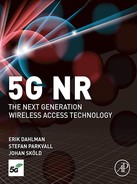
With the overall network architecture in mind, the RAN protocol architecture for the user and control planes can be discussed. Fig. 6.6 illustrates the RAN protocol architecture (the AMF is, as discussed in the previous section, not part of the RAN but is included in the figure for completeness).
In the following, the user-plane protocols will be described in Section 6.4, followed by the control plane protocols in Section 6.5. As seen in Fig. 6.6, many of the protocol entities are common to the user and control planes and hence PDCP, RLC, MAC, and PHY will only be described in the user-plane section.
6.4 User-Plane Protocols
A general overview of the NR user-plane protocol architecture for the downlink is illustrated in Fig. 6.7. Many of the protocol layers are similar to those in LTE, although there are some differences as well. One of the differences is the quality-of-service handling in NR when connected to a 5G core network, where the SDAP protocol layer accepts one or more QoS flows carrying IP packets according to their Quality-of-Service requirements. In the case of the NR user plane connected to the EPC, the SDAP is not used.

As will become clear in the subsequent discussion, not all the entities illustrated in Fig. 6.7 are applicable in all situations. For example, ciphering is not used for broadcasting of the basic system information. The uplink protocol structure is similar to the downlink structure in Fig. 6.7, although there are some differences with respect to, for example, transport-format selection and the control of logical-channel multiplexing.
The different protocol entities of the radio-access network are summarized below and described in more detail in the following sections.
- • Service Data Application Protocol (SDAP) is responsible for mapping QoS bearers to radio bearers according to their quality-of-service requirements. This protocol layer is not present in LTE but introduced in NR when connecting to the 5G core network due to the new quality-of-service handling.
- • Packet Data Convergence Protocol (PDCP) performs IP header compression, ciphering, and integrity protection. It also handles retransmissions, in-sequence delivery, and duplicate removal3 in the case of handover. For dual connectivity with split bearers, PDCP can provide routing and duplication. There is one PDCP entity per radio bearer configured for a device.
- • Radio-Link Control (RLC) is responsible for segmentation and retransmission handling. The RLC provides services to the PDCP in the form of RLC channels. There is one RLC entity per RLC channel (and hence per radio bearer) configured for a device. Compared to LTE, the NR RLC does not support in-sequence delivery of data to higher protocol layers, a change motivated by the reduced delays as discussed below.
- • Medium-Access Control (MAC) handles multiplexing of logical channels, hybrid-ARQ retransmissions, and scheduling and scheduling-related functions. The scheduling functionality is located in the gNB for both uplink and downlink. The MAC provides services to the RLC in the form of logical channels. The header structure in the MAC layer has been changed in NR to allow for more efficient support of low-latency processing than in LTE.
- • Physical Layer (PHY) handles coding/decoding, modulation/demodulation, multi-antenna mapping, and other typical physical-layer functions. The physical layer offers services to the MAC layer in the form of transport channels.
To summarize the flow of downlink data through all the protocol layers, an example illustration with three IP packets, two on one radio bearer and one on another radio bearer, is given in Fig. 6.8. In this example, there are two radio bearers and one RLC SDU is segmented and transmitted in two different transports. The data flow in the case of uplink transmission is similar.

The SDAP protocol maps the IP packets to the different radio bearers; in this example IP packets n and n+1 are mapped to radio bearer x and IP packet m is mapped to radio bearer y. In general, the data entity from/to a higher protocol layer is known as a Service Data Unit (SDU) and the corresponding entity to/from a lower protocol layer entity is called a Protocol Data Unit (PDU). Hence, the output from the SDAP is an SDAP PDU, which equals an PDCP SDU.
The PDCP protocol performs (optional) IP-header compression, followed by ciphering, for each radio bearer. A PDCP header is added, carrying information required for deciphering in the device as well as a sequence number used for retransmission and in-sequence delivery, if configured. The output from the PDCP is forwarded to the RLC.
The RLC protocol performs segmentation of the PDCP PDUs if necessary and adds an RLC header containing a sequence number used for handing retransmissions. Unlike LTE, the NR RLC is not providing in-sequence delivery of data to higher layers. The reason is additional delay incurred by the reordering mechanism, a delay that might be detrimental for services requiring very low latency. If needed, in-sequence delivery can be provided by the PDCP layer instead.
The RLC PDUs are forwarded to the MAC layer, which multiplexes a number of RLC PDUs and attaches a MAC header to form a transport block. Note that the MAC headers are distributed across the MAC PDU, such that the MAC header related to a certain RLC PDU is located immediately prior to the RLC PDU. This is different compared to LTE, which has all the header information at the beginning of the MAC PDU and is motivated by efficient low-latency processing. With the structure in NR, the MAC PDU can be assembled “on the fly” as there is no need to assemble the full MAC PDU before the header fields can be computed. This reduces the processing time and hence the overall latency.
The remainder of this chapter contains an overview of the SDAP, RLC, MAC, and physical layers.
6.4.1 Service Data Adaptation Protocol (SDAP)
The Service Data Adaptation Protocol (SDPA) is responsible for mapping between a quality-of-service flow from the 5G core network and a data radio bearer, as well as marking the quality-of-service flow identifier (QFI) in uplink and downlink packets. The reason for the introduction of SDAP in NR is the new quality-of-service handling compared to LTE when connected to the 5G core. In this case the SDAP is responsible for the mapping between QoS flows and radio bearers as described in Section 6.2. If the gNB is connected to the EPC, as is the case for non-standalone mode, the SDAP is not used.
6.4.2 Packet-Data Convergence Protocol (PDCP)
The PDCP performs IP header compression to reduce the number of bits to transmit over the radio interface. The header-compression mechanism is based on robust header compression (ROHC) framework [38], a set of standardized header-compression algorithms also used for several other mobile-communication technologies. PDCP is also responsible for ciphering to protect against eavesdropping and, for the control plane, integrity protection to ensure that control messages originate from the correct source. At the receiver side, the PDCP performs the corresponding deciphering and decompression operations.
The PDCP is also responsible for duplicate removal and (optional) in-sequence delivery, functions useful, for example, in the case of intra-gNB handover. Upon handover, undelivered downlink data packets will be forwarded by the PDCP from the old gNB to the new gNB. The PDCP entity in the device will also handle retransmission of all uplink packets not yet delivered to the gNB as the hybrid-ARQ buffers are flushed upon handover. In this case, some PDUs may be received in duplicate, both over the connection to the old gNB and the new gNB. The PDCP will in this case remove any duplicates. The PDCP can also be configured to perform reordering to ensure in-sequence delivery of SDUs to higher-layer protocols if desirable.
Duplication in PDCP can also be used for additional diversity. Packets can be duplicated and transmitted on multiple cells, increasing the likelihood of at least one copy being correctly received. This can be useful for services requiring very high reliability. At the receiving end, the PDCP duplicate removal functionality removes any duplicates. In essence, this results in selection diversity.
Dual connectivity is another area where PDCP plays an important role. In dual connectivity, a device is connected to two cells, or in general, two cell groups,4 the Master Cell Group (MCG) and the Secondary Cell Group (SCG). The two cell groups can be handled by different gNBs. A radio bearer is typically handled by one of the cell groups, but there is also the possibility for split bearers, in which case one radio bearer is handled by both cell groups. In this case the PDCP is in charge of distributing the data between the MCG and the SCG, as illustrated in Fig. 6.9.

The June 2018 version of release 15 supports dual connectivity in general, while the December 2017 version is limited to dual connectivity between LTE and NR. This is of particular importance as it is the basis for non-standalone operation using option 3 as illustrated in Fig. 6.4. The LTE-based master cell handles control-plane and (potentially) user-plane signaling, and the NR-based secondary cell handles user-plane only, in essence boosting the data rates.
6.4.3 Radio-Link Control
The RLC protocol is responsible for segmentation of RLC SDUs from the PDCP into suitably sized RLC PDUs. It also handles retransmission of erroneously received PDUs, as well as removal of duplicate PDUs. Depending on the type of service, the RLC can be configured in one of three modes—transparent mode, unacknowledged mode, and acknowledged mode—to perform some or all of these functions. Transparent mode is, as the name suggests, transparent, and no headers are added. Unacknowledged mode supports segmentation and duplicate detection, while acknowledged mode in addition supports retransmission of erroneous packets.
One major difference compared to LTE is that the RLC does not ensure in-sequence delivery of SDUs to upper layers. Removing in-sequence delivery from the RLC reduces the overall latency as later packets do not have to wait for retransmission of an earlier missing packet before being delivered to higher layers but can be forwarded immediately. Another difference is the removal of concatenation from the RLC protocol to allow RLC PDUs to be assembled in advance, prior to receiving the uplink scheduling grant. This also helps reduce the overall latency, as discussed in Chapter 13.
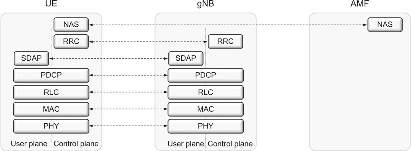
Segmentation, one of the main RLC functions, is illustrated in Fig. 6.10. Included in the figure is also the corresponding LTE functionality, which also supports concatenation. Depending on the scheduler decision, a certain amount of data, that is, certain transport-block size, is selected. As part of the overall low-latency design of NR, the scheduling decision in case of an uplink transmission is known to the device just before transmission, in the order of a few OFDM symbols before. In the case of concatenation in LTE, the RLC PDU cannot be assembled until the scheduling decision is known, which results in an additional delay until the uplink transmission and cannot meet the low-latency requirement of NR. By removing the concatenation from RLC, the RLC PDUs can be assembled in advance and upon receipt of the scheduling decision the device only has to forward a suitable number of RLC PDUs to the MAC layer, the number depending on the scheduled transport block size. To completely fill up the transport block size, the last RLC PDU may contain a segment of an SDU. The segmentation operation is simple. Upon receiving the scheduling grant, the device includes the amount of data needed to fill up the transport block and updates the header to indicate it is a segmented SDU.
The RLC retransmission mechanism is also responsible for providing error-free delivery of data to higher layers. To accomplish this, a retransmission protocol operates between the RLC entities in the receiver and transmitter. By monitoring the sequence numbers indicated in the headers of the incoming PDUs, the receiving RLC can identify missing PDUs (the RLC sequence number is independent of the PDCP sequence number). Status reports are fed back to the transmitting RLC entity, requesting retransmission of missing PDUs. Based on the received status report, the RLC entity at the transmitter can take the appropriate action and retransmit the missing PDUs if needed.
Although the RLC is capable of handling transmission errors due to noise, unpredictable channel variations, etc., error-free delivery is in most cases handled by the MAC-based hybrid-ARQ protocol. The use of a retransmission mechanism in the RLC may therefore seem superfluous at first. However, as will be discussed in Chapter 13, this is not the case and the use of both RLC- and MAC-based retransmission mechanisms is in fact well motivated by the differences in the feedback signaling.
The details of RLC are further described in Section 13.2.
6.4.4 Medium-Access Control
The MAC layer handles logical-channel multiplexing, hybrid-ARQ retransmissions, and scheduling and scheduling-related functions, including handling of different numerologies. It is also responsible for multiplexing/demultiplexing data across multiple component carriers when carrier aggregation is used.
6.4.4.1 Logical Channels and Transport Channels
The MAC provides services to the RLC in the form of logical channels. A logical channel is defined by the type of information it carries and is generally classified as a control channel, used for transmission of control and configuration information necessary for operating an NR system, or as a traffic channel, used for the user data. The set of logical-channel types specified for NR includes:
- • The Broadcast Control Channel (BCCH), used for transmission of system information from the network to all devices in a cell. Prior to accessing the system, a device needs to acquire the system information to find out how the system is configured and, in general, how to behave properly within a cell. Note that, in the case of non-standalone operation, system information is provided by the LTE system and there is no BCCH.
- • The Paging Control Channel (PCCH), used for paging of devices whose location on a cell level is not known to the network. The paging message therefore needs to be transmitted in multiple cells. Note that, in the case of non-standalone operation, paging is provided by the LTE system and there is no PCCH.
- • The Common Control Channel (CCCH), used for transmission of control information in conjunction with random access.
- • The Dedicated Control Channel (DCCH), used for transmission of control information to/from a device. This channel is used for individual configuration of devices such as setting various parameters in devices.
- • The Dedicated Traffic Channel (DTCH), used for transmission of user data to/from a device. This is the logical channel type used for transmission of all unicast uplink and downlink user data.
The above logical channels are in general present also in an LTE system and used for similar functionality. However, LTE provides additional logical channels for features not yet supported by NR (but likely to be introduced in upcoming releases).
From the physical layer, the MAC layer uses services in the form of transport channels. A transport channel is defined by how and with what characteristics the information is transmitted over the radio interface. Data on a transport channel are organized into transport blocks. In each Transmission Time Interval (TTI), at most one transport block of dynamic size is transmitted over the radio interface to/from a device (in the case of spatial multiplexing of more than four layers, there are two transport blocks per TTI).
Associated with each transport block is a Transport Format (TF), specifying how the transport block is to be transmitted over the radio interface. The transport format includes information about the transport-block size, the modulation-and-coding scheme, and the antenna mapping. By varying the transport format, the MAC layer can thus realize different data rates, a process known as transport-format selection.
The following transport-channel types are defined for NR:
- • The Broadcast Channel (BCH) has a fixed transport format, provided by the specifications. It is used for transmission of parts of the BCCH system information, more specifically the so-called Master Information Block (MIB), as described in Chapter 16.
- • The Paging Channel (PCH) is used for transmission of paging information from the PCCH logical channel. The PCH supports discontinuous reception (DRX) to allow the device to save battery power by waking up to receive the PCH only at predefined time instants.
- • The Downlink Shared Channel (DL-SCH) is the main transport channel used for transmission of downlink data in NR. It supports key NR features such as dynamic rate adaptation and channel-dependent scheduling in the time and frequency domains, hybrid ARQ with soft combining, and spatial multiplexing. It also supports DRX to reduce device power consumption while still providing an always-on experience. The DL-SCH is also used for transmission of the parts of the BCCH system information not mapped to the BCH. Each device has a DL-SCH per cell it is connected to. In slots where system information is received there is one additional DL-SCH from the device perspective.
- • The Uplink Shared Channel (UL-SCH) is the uplink counterpart to the DL-SCH—that is, the uplink transport channel used for transmission of uplink data.
In addition, the Random-Access Channel (RACH) is also defined as a transport channel, although it does not carry transport blocks.
Part of the MAC functionality is multiplexing of different logical channels and mapping of the logical channels to the appropriate transport channels. The mapping between logical-channel types and transport-channel types is given in Fig. 6.11. This figure clearly indicates how DL-SCH and UL-SCH are the main downlink and uplink transport channels, respectively. In the figures, the corresponding physical channels, described further below, are also included and the mapping between transport channels and physical channels is illustrated.

To support priority handling, multiple logical channels, where each logical channel has its own RLC entity, can be multiplexed into one transport channel by the MAC layer. At the receiver, the MAC layer handles the corresponding demultiplexing and forwards the RLC PDUs to their respective RLC entity. To support the demultiplexing at the receiver, a MAC header is used. The placement of the MAC headers has been improved compared to LTE, again with low-latency operation in mind. Instead of locating all the MAC header information at the beginning of a MAC PDU, which implies that assembly of the MAC PDU cannot start until the scheduling decision is available, the subheader corresponding to a certain MAC SDU is placed immediately before the SDU, as shown in Fig. 6.12. This allows the PDUs to be preprocessed before having received the scheduling decision. If necessary, padding can be appended to align the transport block size with those supported in NR.

The subheader contains the identity of the logical channel (LCID) from which the RLC PDU originated and the length of the PDU in bytes. There is also a flag indicating the size of the length indicator, as well as a reserved bit for future use.
In addition to multiplexing of different logical channels, the MAC layer can also insert MAC control elements into the transport blocks to be transmitted over the transport channels. A MAC control element is used for inband control signaling and identified with reserved values in the LCID field, where the LCID value indicates the type of control information. Both fixed- and variable-length MAC control elements are supported, depending on their usage. For downlink transmissions, MAC control elements are located at the beginning of the MAC PDU, while for uplink transmissions the MAC control elements are located at the end, immediately before the padding (if present). Again, the placement is chosen in order to facilitate low-latency operation in the device.
MAC control elements are, as mentioned above, used for inband control signaling. It provides a faster way to send control signaling than RLC, without having to resort to the restrictions in terms of payload sizes and reliability offered by physical-layer L1/L2 control signaling (PDCCH or PUCCH). There are multiple MAC control elements, used for various purposes, for example:
- • Scheduling-related MAC control elements, such as buffer status reports and power headroom reports used to assist uplink scheduling as described in Chapter 14, and the configured grant confirmation MAC control element used when configuring semipersistent scheduling;
- • Random-access-related MAC control elements such as the C-RNTI and contention-resolution MAC control elements;
- • Timing-advance MAC control elements to handle timing advance as described in Chapter 15;
- • Activation and deactivation of previously configured components;
- • DRX-related MAC control elements;
- • Activation/deactivation of PDCP duplication detection; and
- • Activation/deactivation of CSI reporting and SRS transmission (see Chapter 8).
The MAC entity is also responsible for distributing data from each flow across the different component carriers, or cells, in the case of carrier aggregation. The basic principle for carrier aggregation is independent processing of the component carriers in the physical layer, including control signaling, scheduling, and hybrid-ARQ retransmissions, while carrier aggregation is invisible above the MAC layer. Carrier aggregation is therefore mainly seen in the MAC layer, as illustrated in Fig. 6.13, where logical channels, including any MAC control elements, are multiplexed to form transport blocks per component carrier with each component carrier having its own hybrid-ARQ entity.

Both carrier aggregation and dual connectivity result in the device being connected to more than one cell. Despite this similarity, there are fundamental differences, primarily related to how tightly the different cells are coordinated and whether they reside in the same or in different gNBs.
Carrier aggregation implies very tight coordination, with all the cells belonging to the same gNB. Scheduling decisions are taken jointly for all the cells the device is connected to by one joint scheduler.
Dual connectivity, on the other hand, allows for a much looser coordination between the cells. The cells can belong to different gNBs, and they may even belong to different radio-access technologies as is the case for NR-LTE dual connectivity in case of non-standalone operation.
Carrier aggregation and dual connectivity can also be combined. This is the reason for the terms master cell group and secondary cell group. Within each of the cell groups, carrier aggregation can be used.
6.4.4.2 Scheduling
One of the basic principles of NR radio access is shared-channel transmission—that is, time–frequency resources are dynamically shared between users. The scheduler is part of the MAC layer (although often better viewed as a separate entity) and controls the assignment of uplink and downlink resources in terms of so-called resource blocks in the frequency domain and OFDM symbols and slots in the time domain.
The basic operation of the scheduler is dynamic scheduling, where the gNB takes a scheduling decision, typically once per slot, and sends scheduling information to the selected set of devices. Although per-slot scheduling is a common case, neither the scheduling decisions, nor the actual data transmission is restricted to start or end at the slot boundaries. This is useful to support low-latency operation as well as future extensions to unlicensed spectrum operation as mentioned in Chapter 6.
Uplink and downlink scheduling are separated in NR, and uplink and downlink scheduling decisions can be taken independently of each other (within the limits set by the duplex scheme in the case of half-duplex operation).
The downlink scheduler is responsible for (dynamically) controlling which device(s) to transmit to and, for each of these devices, the set of resource blocks upon which the device’s DL-SCH should be transmitted. Transport-format selection (selection of transport-block size, modulation scheme, and antenna mapping) and logical-channel multiplexing for downlink transmissions are controlled by the gNB, as illustrated in the left part of Fig. 6.14.

The uplink scheduler serves a similar purpose, namely to (dynamically) control which devices are to transmit on their respective UL-SCH and on which uplink time–frequency resources (including component carrier). Despite the fact that the gNB scheduler determines the transport format for the device, it is important to point out that the uplink scheduling decision does not explicitly schedule a certain logical channel but rather the device as such. Thus, although the gNB scheduler controls the payload of a scheduled device, the device is responsible for selecting from which radio bearer(s) the data are taken according to a set of rules, the parameters of which can be configured by the gNB. This is illustrated in the right part of Fig. 6.14, where the gNB scheduler controls the transport format and the device controls the logical-channel multiplexing.
Although the scheduling strategy is implementation specific and not specified by 3GPP, the overall goal of most schedulers is to take advantage of the channel variations between devices and preferably schedule transmissions to a device on resources with advantageous channel conditions in both the time and frequency domain, often referred to as channel-dependent scheduling.
Downlink channel-dependent scheduling is supported through channel-state information (CSI), reported by the device to the gNB and reflecting the instantaneous downlink channel quality in the time and frequency domains, as well as information necessary to determine the appropriate antenna processing in the case of spatial multiplexing. In the uplink, the channel-state information necessary for uplink channel-dependent scheduling can be based on a sounding reference signal transmitted from each device for which the gNB wants to estimate the uplink channel quality. To aid the uplink scheduler in its decisions, the device can transmit buffer-status and power-headroom information to the gNB using MAC control elements. This information can only be transmitted if the device has been given a valid scheduling grant. For situations when this is not the case, an indicator that the device needs uplink resources is provided as part of the uplink L1/L2 control-signaling structure (see Chapter 10).
Although dynamic scheduling is the baseline mode-of-operation, there is also a possibility for transmission/reception without a dynamic grant to reduce the control-signaling overhead. The details differ between downlink and uplink.
In the downlink, a scheme similar to semipersistent scheduling in LTE is used. A semistatic scheduling pattern is signaled in advance to the device. Upon activation by L1/L2 control signaling, which also includes parameters such as the time–frequency resources and coding-and-modulation scheme to use, the device receives downlink data transmissions according to the preconfigured pattern.
In the uplink, there are two slightly different schemes, type 1 and type 2, differing on how to activate the scheme. In type 1, RRC configures all parameters, including the time–frequency resources and the modulation-and-coding scheme to use, and also activates the uplink transmission according to the parameters. Type 2, on the other hand, is similar to semipersistent scheduling where RRC configures the scheduling pattern in time. Activation is done using L1/L2 signaling, which includes the necessary transmission parameters (except the periodicity which is provides through RRC signaling). In both type 1 and type 2, the device does not transmit in the uplink unless there are data to convey.
6.4.4.3 Hybrid ARQ With Soft Combining
Hybrid ARQ with soft combining provides robustness against transmission errors. As hybrid-ARQ retransmissions are fast, many services allow for one or multiple retransmissions, and the hybrid-ARQ mechanism therefore forms an implicit (closed loop) rate-control mechanism. The hybrid-ARQ protocol is part of the MAC layer, while the physical layer handles the actual soft combining.5
Hybrid ARQ is not applicable for all types of traffic. For example, broadcast transmissions, where the same information is intended for multiple devices, typically do not rely on hybrid ARQ. Hence, hybrid ARQ is only supported for the DL-SCH and the UL-SCH, although its usage is up to the gNB implementation.
The hybrid-ARQ protocol uses multiple parallel stop-and-wait processes in a similar way to LTE. Upon receipt of a transport block, the receiver tries to decode the transport block and informs the transmitter about the outcome of the decoding operation through a single acknowledgment bit indicating whether the decoding was successful or if a retransmission of the transport block is required. Clearly, the receiver must know to which hybrid-ARQ process a received acknowledgment is associated. This is solved by using the timing of the acknowledgment for association with a certain hybrid-ARQ process or by using the position of the acknowledgment in the hybrid-ARQ codebook in case of multiple acknowledgments transmitted at the same time (see Section 13.1 for further details).
An asynchronous hybrid-ARQ protocol is used for both downlink and uplink—that is, an explicit hybrid-ARQ process number is used to indicate which process is being addressed. In an asynchronous hybrid-ARQ protocol, the retransmissions are in principle scheduled similarly to the initial transmissions. The use of an asynchronous uplink protocol, instead of a synchronous one as in LTE, is necessary to support dynamic TDD where there is no fixed uplink/downlink allocation. It also offers better flexibility in terms of prioritization between data flows and devices and is beneficial for future extension to unlicensed spectrum operation.6
Up to 16 hybrid-ARQ processes are supported. Having a larger maximum number of hybrid-ARQ processes than in LTE7 is motivated by the possibility for remote radio heads, which incurs a certain front-haul delay, together with the shorter slot durations at high frequencies. It is important though, that the larger number of maximum hybrid-ARQ processes does not imply a longer roundtrip time as not all processes need to be used, it is only an upper limit of the number of processes possible.
The use of multiple parallel hybrid-ARQ processes, illustrated in Fig. 6.15, for a device can result in data being delivered from the hybrid-ARQ mechanism out of sequence. For example, transport block 3 in the figure was successfully decoded before transport block 2, which required retransmissions. For many applications this is acceptable and, if not, in-sequence delivery can be provided through the PDCP protocol. The reason for not providing in-sequence delivery in the RLC protocol is to reduce latency. If in-sequence delivery would be enforced in Fig. 6.15, packet numbers 3, 4, and 5 would have to be delayed until packet number 2 is correctly received before delivering them to higher layers, while without in-sequence delivery each packet can be forwarded as soon as it is correctly received.

One additional feature of the hybrid-ARQ mechanism in NR compared to LTE is the possibility for retransmission of codeblock groups, a feature that can be beneficial for very large transport blocks or when a transport block is partially interfered by another preempting transmission. As part of the channel-coding operation in the physical layer, a transport block is split into one or more codeblocks with error-correcting coding applied to each of the codeblocks of at most 8448 bits8 in order to keep the channel-coding complexity reasonable. Thus, even for modest data rates there can be multiple code blocks per transport block and at Gbps data rates there can be hundreds of code blocks per transport block. In many cases, especially if the interference is bursty and hits a small number of OFDM symbols in the slot, only a few of these code blocks in the transport block may be corrupted, while the majority of code blocks are correctly received. To correctly receive the transport block, it is sufficient to retransmit the erroneous code blocks. At the same time, the control signaling overhead would be too large if individual code blocks can be addressed by the hybrid-ARQ mechanism. Therefore, codeblock groups (CBGs) are defined. If per-CBG retransmission is configured, feedback is provided per CBG and only the erroneously received code block groups are retransmitted (Fig. 6.16). This can consume less resource than retransmitting the whole transport block. CBG retransmissions are invisible to the MAC layer and are handled in the physical layer, despite being part of the hybrid-ARQ mechanism. The reason for this is not technical but purely related to the specification structure. From a MAC perspective, the transport block is not correctly received until all the CBGs are correctly received. It is not possible, in the same hybrid-ARQ process, to mix transmission of new CBGs belonging to another transport block with retransmissions of CBGs belonging to the incorrectly received transport block.

The hybrid-ARQ mechanism will rapidly correct transmission errors due to noise or unpredictable channel variations. As discussed above, the RLC is also capable of requesting retransmissions, which at first sight may seem unnecessary. However, the reason for having two retransmission mechanisms on top of each other can be seen in the feedback signaling—hybrid ARQ provides fast retransmissions but due to errors in the feedback the residual error rate is typically too high for, for example, good TCP performance, while RLC ensures (almost) error-free data delivery but slower retransmissions than the hybrid-ARQ protocol. Hence, the combination of hybrid ARQ and RLC provides an attractive combination of small round-trip time and reliable data delivery.
6.4.5 Physical Layer
The physical layer is responsible for coding, physical-layer hybrid-ARQ processing, modulation, multi-antenna processing, and mapping of the signal to the appropriate physical time–frequency resources. It also handles mapping of transport channels to physical channels, as shown in Fig. 6.11.
As mentioned in the introduction, the physical layer provides services to the MAC layer in the form of transport channels. Data transmissions in downlink and uplink use the DL-SCH and UL-SCH transport-channel types, respectively. There is at most one transport block (two transport blocks in the case of spatial multiplexing of more than four layers in the downlink) to a single device per TTI on a DL-SCH or UL-SCH. In the case of carrier aggregation, there is one DL-SCH (or UL-SCH) per component carrier seen by the device.
A physical channel corresponds to the set of time–frequency resources used for transmission of a particular transport channel and each transport channel is mapped to a corresponding physical channel, as shown in Fig. 6.11. In addition to the physical channels with a corresponding transport channel, there are also physical channels without a corresponding transport channel. These channels, known as L1/L2 control channels, are used for downlink control information (DCI), providing the device with the necessary information for proper reception and decoding of the downlink data transmission, and uplink control information (UCI) used for providing the scheduler and the hybrid-ARQ protocol with information about the situation at the device.
The following physical-channel types are defined for NR:
- • The Physical Downlink Shared Channel (PDSCH) is the main physical channel used for unicast data transmission, but also for transmission of, for example, paging information, random-access response messages, and delivery of parts of the system information.
- • The Physical Broadcast Channel (PBCH) carries part of the system information, required by the device to access the network.
- • The Physical Downlink Control Channel (PDCCH) is used for downlink control information, mainly scheduling decisions, required for reception of PDSCH, and for scheduling grants enabling transmission on the PUSCH.
- • The Physical Uplink Shared Channel (PUSCH) is the uplink counterpart to the PDSCH. There is at most one PUSCH per uplink component carrier per device.
- • The Physical Uplink Control Channel (PUCCH) is used by the device to send hybrid-ARQ acknowledgments, indicating to the gNB whether the downlink transport block(s) was successfully received or not, to send channel-state reports aiding downlink channel-dependent scheduling, and for requesting resources to transmit uplink data upon.
- • The Physical Random-Access Channel (PRACH) is used for random access.
Note that some of the physical channels, more specifically the channels used for downlink and uplink control information (PDCCH and PUCCH) do not have a corresponding transport channel mapped to them.
6.5 Control-Plane Protocols
The control-plane protocols are, among other things, responsible for connection setup, mobility, and security.
The NAS control-plane functionality operates between the AMF in the core network and the device. It includes authentication, security, and different idle-mode procedures such as paging (described below). It is also responsible for assigning an IP address to a device.
The Radio Resource Control (RRC) control-plane functionality operates between the RRC located in the gNB. RRC is responsible for handling the RAN-related control-plane procedures, including:
- • Broadcast of system information necessary for the device to be able to communicate with a cell. Acquisition of system information is described in Chapter 16.
- • Transmission of paging messages originating from the MME to notify the device about incoming connection requests. Paging is used in the RRC_IDLE state (described further below) when the device is not connected to a cell. Indication of system-information updates is another use of the paging mechanism, as is public warning systems.
- • Connection management, including setting up bearers and mobility. This includes establishing an RRC context—that is, configuring the parameters necessary for communication between the device and the radio-access network.
- • Mobility functions such as cell (re)selection.
- • Measurement configuration and reporting.
- • Handling of device capabilities; when connection is established the device will announce its capabilities as not all devices are capable of supporting all the functionality described in the specifications.
RRC messages are transmitted to the device using signaling radio bearers (SRBs), using the same set of protocol layers (PDCP, RLC, MAC, and PHY) as described in Section 6.4. The SRB is mapped to the common control channel (CCCH) during establishment of connection and, once a connection is established, to the dedicated control channel (DCCH). Control-plane and user-plane data can be multiplexed in the MAC layer and transmitted to the device in the same TTI. The aforementioned MAC control elements can also be used for control of radio resources in some specific cases where low latency is more important than ciphering, integrity protection, and reliable transfer.
6.5.1 RRC State Machine
In most wireless communication systems, the device can be in different states depending on the traffic activity. This is true also for NR and an NR device can be in one of three RRC states, RRC_IDLE, RRC_ACTIVE, and RRC_INACTIVE (see Fig. 6.17). The first two RRC states, RRC_IDLE and RRC_CONNECTED, are similar to the counterparts in LTE, while RRC_INACTIVE is a new state introduced in NR and not present in the original LTE design. There are also core network states not discussed further herein, CN_IDLE and CN_CONNECTED, depending on whether the device has established a connection with the core network or not.

In RRC_IDLE, there is no RRC context—that is, the parameters necessary for communication between the device and the network—in the radio-access network and the device does not belong to a specific cell. From a core network perspective, the device is in the CN_IDLE state. No data transfer may take place as the device sleeps most of the time to reduce battery consumption. In the downlink, devices in idle state periodically wake up to receive paging messages, if any, from the network. Mobility is handled by the device through cell reselection (see Section 6.5.2). Uplink synchronization is not maintained and hence the only uplink transmission activity that may take place is random access, discussed in Chapter 16, to move to a connected state. As part of moving to a connected state, the RRC context is established in both the device and the network.
In RRC_CONNECTED, the RRC context is established and all parameters necessary for communication between the device and the radio-access network are known to both entities. From a core network perspective, the device is in the CN_CONNECTED state. The cell to which the device belongs is known and an identity of the device, the Cell Radio-Network Temporary Identifier (C-RNTI), used for signaling purposes between the device and the network, has been configured. The connected state is intended for data transfer to/from the device, but discontinuous reception (DRX) can be configured to reduce device power consumption (DRX is described in further detail in Section 14.5). Since there is an RRC context established in the gNB in the connected state, leaving DRX and starting to receive/transmit data is relatively fast as no connection setup with its associated signaling is needed. Mobility is managed by the radio-access network, that is, the device provides neighboring-cell measurements to the network which commands the device to perform a handover when relevant. Uplink time alignment may or may not exist but need to be established using random access and maintained as described in Section 16.2 for data transmission to take place.
In LTE, only idle and connected states are supported. A common case in practice is to use the idle state as the primary sleep state to reduce the device power consumption. However, as frequent transmission of small packets is common for many smartphone applications, the result is a significant amount of idle-to-active transitions in the core network. These transitions come at a cost in terms of signaling load and associated delays. Therefore, to reduce the signaling load and in general reduce the latency, a third state is defined in NR, the RRC_INACTIVE state.
In RRC_INACTIVE, the RRC context is kept in both the device and the gNB. The core network connection is also kept, that is, the device is in CN_CONNECTED from a core network perspective. Hence, transition to connected state for data transfer is fast. No core network signaling is needed. The RRC context is already in place in the network and idle-to-active transitions can be handled in the radio-access network. At the same time, the device is allowed to sleep in a similar way as in the idle state and mobility is handled through cell reselection, that is, without involvement of the network. Thus, RRC_INACTIVE can be seen as a mix of the idle and connected states.9
As seen from the discussion above, one important difference between the different states is the mobility mechanisms involved. Efficient mobility handling is a key part of any mobile communication system. For the idle and inactive states, mobility is handled by the device through cell reselection, while for the connected mode, mobility is handled by the radio-access network based on measurements. The different mobility mechanisms are described below, starting with idle- and inactive-mode mobility.
6.5.2 Idle-State and Inactive-State Mobility
The purpose of the mobility mechanism in idle and inactive states is to ensure that a device is reachable by the network. The network does this by notifying the device by means of a paging message. The area over which such a paging message is transmitted is a key aspect of the paging mechanism and in idle and inactive modes, the device is in control on when to update this information. This is sometimes referred to as cell reselection. In essence, the device searches for and measures on candidate cells similar to the initial cell search as described in Chapter 16. Once the device discovers a cell with a received power sufficiently higher than its current one, it considered this as the best cell and, if necessary, contacts the network through random access.
6.5.2.1 Tracking the Device
In principle, the network could transmit the page to the device over the entire coverage of the network, by broadcasting the paging message from every cell. However, that would obviously imply a very high overhead in terms of paging-message transmissions as the vast majority of the paging transmissions would take place in cells where the target device is not located. On the other hand, if the paging message is only to be transmitted in the cell in which the device is located, there is a need to track the device on a cell level. This would imply that the device would have to inform the network every time it moves out of the coverage of one cell and into the coverage of another cell. This would also lead to very high overhead, in this case in terms of the signaling needed to inform the network about the updated device location. For this reason, a compromise between these two extremes is typically used, where devices are only tracked on a cell-group level:
For NR, the basic principle for such tracking is the same for idle state and inactive state, although the grouping is somewhat different in the two cases.
As illustrated in Fig. 6.18, NR cells are grouped into RAN Areas, where each RAN Area is identified by an RAN Area Identifier (RAI). The RAN Areas, in turn, are grouped into even larger Tracking Areas, with each Tracking Area being identified by a Tracking Area Identifier (TAI). Thus, each cell belongs to one RAN Area and one Tracking Area, the identities of which are provided as part of the cell system information.

The Tracking Areas are the basis for device tracking on core-network level. Each device is assigned a UE Registration Area by the core network, consisting of a list of tracking area identifiers. When a device enters a cell that belongs to a Tracking Area not included in the assigned UE Registration Area it accesses the network, including the core network, and performs a NAS Registration Update. The core network registers the device location and updates the device UE Registration Area, in practice providing the device with a new TAI list that includes the new TAI.
The reason the device is assigned a set of TAIs, that is, a set of Tracking Areas, is to avoid repeated NAS Registration Updates if a device moves back and forth over the border of two neighbor Tracking Areas. By keeping the old TAI within the updated UE Registration Area no new update is needed if the device moves back into the old TAI.
The RAN Area is the basis for device tracking on radio-access-network level. UEs in inactive state can be assigned a RAN Notification Area that consists of either of the following:
Note the first case is essentially the same as having each RAN Area consist of a single cell, while the last case is essentially the same as having the RAN Areas coincide with the Tracking Areas.
The procedure for RAN Notification Area updates is similar to updates of the UE Registration Area. When a device enters a cell that is not directly or indirectly (via a RAN/Tracking Area) included in the RAN Notification Area, the device accesses the network and makes an RRC RAN Notification Area Update. The radio network registers the device location and updates the device RAN Notification Area. As a change of Tracking Area always implies a change also of the device RAN Area, an RRC RAN Notification Area update is done implicitly every time a device makes a UE Registration update.
In order to track its movement within the network, the device searches for and measures on SS blocks similar to the initial cell search as described in Chapter 16. Once the device discovers an SS block with a received power that exceeds the received power of its current SS block by a certain threshold it reads the system information (SIB1) of the new cell in order to acquire information about the Tracking and RAN Areas.
6.5.2.2 Paging Message Transmission
Similar to the delivery of system information, paging messages are provided by means of ordinary scheduled PDSCH transmissions. In order to allow for low device energy consumption, a device is only supposed to wake up at specific time instances, for example, once every 100 ms or even less often, to monitor for paging messages. Paging messages are indicated by a specific PI-RNTI carried within the DCI. Once detecting such a DCI, the device demodulates and decodes the corresponding PDSCH to extract the paging message(s). Note that there can be multiple paging messages, corresponding to different devices, within the same paging transmission. The PI-RNTI is thus a shared identity.
6.5.3 Connected-State Mobility
In a connected state the device has a connection established to the network. The aim of connected-state mobility is to ensure that this connectivity is retained without any interruption or noticeable degradation as the device moves within the network.
To ensure this, the device continuously searches for new cells both on the current carrier frequency (intra-frequency measurements) and on different carrier frequencies (inter-frequency measurements) that the device has been informed about. Such measurements can be done on an SS block in essentially the same way as for initial access and cell search in idle and inactive mode (see above). However, measurements can also be done on configured CSI-RS.
In a connected state, the device does not make any decisions of its own when it comes to handover to a different cell. Rather, based on different triggering conditions, for example, the relative power of a measured SS block compared to the current cell, the device reports the result of the measurements to the network. Based on this reporting the network makes a decision as to whether or not the device is to handover to a new cell. It should be pointed out that this reporting is done using RRC signaling, that is, it is not covered by the Layer-1 measurement and reporting framework (Chapter 8) used, for example, for beam management.
Except for very small cells that are tightly synchronized to each other, the current uplink transmission timing of a device will typically not match the new cell to which a device is assumed to handover. To establish synchronization to a new cell a device thus has to carry out a procedure similar to the random-access procedure of Chapter 16. However, this may then be a contention-free random access using resources specifically assigned to the device with no risk for collision but only aiming at establishing synchronization to the new cell. Thus, only the two first steps of the random-access procedure are needed, that is, the preamble transmission and corresponding random-access response providing the device with updated transmission timing.