
Initial Access
Abstract
This chapter provides a detailed description of NR cell search, system-information delivery, and random access. Especially, the NR-specific features related to beam forming and ultra-lean transmission are highlighted.
Keywords
Cell search; SS block; PSS; SSS; PBCH; system information; random access; preamble transmission
Within NR, the initial-access functionality includes:
- • The functions and procedures by which a device initially finds a cell when entering the coverage area of a system;
- • The functions and procedures by which a device in idle/inactive state accesses the network, typically to request the set-up of a connection and commonly referred to as random access.
To quite a large extent, similar functionality is also used in other situations. The basic network signals used to initially find a cell can, for example, also be used to find new cells when a device is moving within the coverage area of the network. Furthermore, when accessing a new cell, the same basic random-access procedure as for initial access may be used. The random-access procedure may also be used by a device in connected state, for example, to request resources for uplink transmission or to re-establish uplink synchronization.
In this chapter, the details of cell search, system-information delivery, and random access are described.
16.1 Cell Search
Cell search covers the functions and procedures by which a device finds new cells. Cell search is carried out when a device is initially entering the coverage area of a system. To enable mobility, cell search is also continuously carried out by devices moving within the system, both when the device is connected to the network and when in idle/inactive state. Here we will describe cell search based on so-called SS blocks, which are used for initial cell search as well as idle/inactive-state mobility. Cell search based on SS blocks can also be used for connected-state mobility, although in that case cell search can also be based on CSI-RS explicitly configured for the device.
16.1.1 The SS Block
To enable devices to find a cell when entering a system, as well as to find new cells when moving within the system, a synchronization signal consisting of two parts, the Primary Synchronization Signal (PSS) and the Secondary Synchronization Signal (SSS), is periodically transmitted on the downlink from each NR cell. The PSS/SSS, together with the Physical Broadcast Channel (PBCH), is jointly referred to as a Synchronization Signal Block or SS block.1
The SS block serves a similar purpose and, in many respects, has a similar structure as the PSS/SSS/PBCH of LTE [28].2 However, there are some important differences between the LTE PSS/SSS/PBCH and the NR SS block. At least partly, the origin of these differences can be traced back to some NR-specific requirements and characteristics including the aim to reduce the amount of “always-on” signals, as discussed in Section 5.2, and the possibility for beam-forming during initial access.
As with all NR downlink transmissions, SS-block transmission is based on OFDM. In other words, the SS block is transmitted on a set of time/frequency resources (resource elements) within the basic OFDM grid discussed in Section 7.3. Fig. 16.1 illustrates the time/frequency structure of a single SS block transmission. As can be seen, the SS block spans four OFDM symbols in the time domain and 240 subcarriers in the frequency domain.
- • The PSS is transmitted in the first OFDM symbol of the SS block and occupies 127 subcarriers in the frequency domain. The remaining subcarriers are empty.
- • The SSS is transmitted in the third OFDM symbol of the SS block and occupies the same set of subcarriers as the PSS. There are eight and nine empty subcarriers on each side of the SSS.
- • The PBCH is transmitted within the second and fourth OFDM symbols of the SS block. In addition, PBCH transmission also uses 48 subcarriers on each side of the SSS.

The total number of resource elements used for PBCH transmission per SS block thus equals 576. Note that this includes resource elements for the PBCH itself but also resource elements for the demodulation reference signals (DMRS) needed for coherent demodulation of the PBCH.
Different numerologies can be used for SS block transmission. However, to limit the need for devices to simultaneously search for SS blocks of different numerologies, there is in many cases only a single SS-block numerology defined for a given frequency band.
Table 16.1 lists the different numerologies applicable for SS-block transmission together with the corresponding SS-block bandwidth and time duration, and the frequency range for which each specific numerology applies.3 Note that 60 kHz numerology cannot be used for SS-block transmission regardless of frequency range. In contrast, 240 kHz numerology can be used for SS-block transmission although it is currently not supported for other downlink transmissions. The reason to support 240 kHz SS-block numerology is to enable a very short time duration for each SS block. This is relevant in the case of beam-sweeping over many beams with a corresponding large number of time multiplexed SS blocks (see further details in Section 16.1.4).
Table 16.1
| Numerology (kHz) | SSB Bandwidtha (MHz) | SSB Duration (μs) | Frequency Range |
|---|---|---|---|
| 15 | 3.6 | ≈285 | FR1 (<3 GHz) |
| 30 | 7.2 | ≈143 | FR1 |
| 120 | 28.8 | ≈36 | FR2 |
| 240 | 57.6 | ≈18 | FR2 |

aThe SS-block bandwidth is simply the number of subcarriers used for SS block (240) multiplied by the SS-block subcarrier spacing.
16.1.2 Frequency-Domain Position of SS Block
In LTE, the PSS and SSS are always located at the center of the carrier. Thus, once an LTE device has found a PSS/SSS, that is, found a carrier, it inherently knows the center frequency of the found carrier. The drawback with this approach, that is, always locating the PSS/SSS at the center of the carrier, is that a device with no a priori knowledge of the frequency-domain carrier position must search for PSS/SSS at all possible carrier positions (the “carrier raster”).
To allow for faster cell search, a different approach has been adopted for NR. Rather than always being located at the center of the carrier, implying that the possible SS-block locations coincide with the carrier raster, there are, within each frequency band, a more limited set of possible locations of SS block, referred to as the “synchronization raster”. Instead of searching for an SS block at each position of the carrier raster, a device thus only needs to search for an SS block on the sparser synchronization raster.
As carriers can still be located at an arbitrary position on the more dense carrier raster, the SS block may not end up at the center of a carrier. The SS block may not even end up aligned with the resource-block grid. Hence, once the SS block has been found, the device must be explicitly informed about the exact SS-block frequency-domain position within the carrier. This is done by means of information partly within the SS block itself, more specifically information carried by the PBCH (Section 16.1.5.3), and partly within the remaining broadcast system information (see further Section 6.1.6).
16.1.3 SS Block Periodicity
The SS block is transmitted periodically with a period that may vary from 5 ms up to 160 ms. However, devices doing initial cell search, as well as devices in inactive/idle state doing cell search for mobility, can assume that the SS block is repeated at least once every 20 ms. This allows for a device that searches for an SS block in the frequency domain to know how long it must stay on each frequency before concluding that there is no PSS/SSS present and that it should move on to the next frequency within the synchronization raster.
The 20 ms SS-block periodicity is four times longer than the corresponding 5 ms periodicity of LTE PSS/SSS transmission. The longer SS-block period was selected to allow for enhanced NR network energy performance and in general to follow the ultra-lean design paradigm described in Section 5.2. The drawback with a longer SS-block period is that a device must stay on each frequency for a longer time in order to conclude that there is no PSS/SSS on the frequency. However, this is compensated for by the sparse synchronization raster discussed above, which reduces the number of frequency-domain locations on which a device must search for an SS block.
Even though devices doing initial cell search can assume that the SS block is repeated at least once every 20 ms, there are situations when there may be reasons to use either a shorter or longer SS-block periodicity:
- • A shorter SS-block periodicity may be used to enable faster cell search for devices in connected mode.
- • A longer SS-block periodicity may be used to further enhance network energy performance. A carrier with an SS-block periodicity larger than 20 ms may not be found by devices doing initial access. However, such a carrier could still be used by devices in connected mode, for example, as a secondary carrier in a carrier-aggregation scenario.
It should be noted that there is even the possibility to deploy secondary carriers without any SS block.
16.1.4 SS Burst Set: Multiple SS Blocks in the Time Domain
One key difference between the SS block and the corresponding signals for LTE is the possibility to apply beam-sweeping for SS-block transmission, that is, the possibility to transmit SS blocks in different beams in a time-multiplexed fashion (see Fig. 16.2). The set of SS blocks within a beam-sweep is referred to as an SS burst set.4 Note that the SS-block period discussed in the previous section is the time between SS-block transmissions within a specific beam, that is, it is actually the periodicity of the SS burst set. This makes sense as a device located in a certain downlink beam may only “see” a single SS block and be unaware of any other SS blocks transmitted from the cell.

By applying beam-forming for the SS block, the coverage of a single SS-block transmission is increased. Beam-sweeping for SS-block transmission also enables receiver-side beam-sweeping for the reception of uplink random-access transmissions as well as downlink beam-forming for the random-access response (see further details in Section 16.2.1.5).
Although the periodicity of the SS burst set is flexible with a minimum period of 5 ms and a maximum period of 160 ms, each SS burst set is always confined to a 5 ms time interval, either in the first or second half of a 10 ms frame.
The maximum number of SS blocks within an SS burst set is different for different frequency bands.
- • For frequency bands below 3 GHz, there can be up to four SS blocks within an SS burst set, enabling SS-block beam-sweeping over up to four beams;
- • For frequency bands between 3 GHz and 6 GHz, there can be up to eight SS blocks within an SS burst set, enabling beam-sweeping over up to eight beams;
- • For higher-frequency bands (FR2) there can be up to 64 SS blocks within an SS burst set, enabling beam-sweeping over up to 64 beams.
There are two reasons why the maximum number of SS blocks within an SS burst set, and thus also the maximum number of beams over which the SS block can be swept, is larger for higher-frequency bands.
- • The use of a large number of beams with more narrow beam-width is typically more relevant for higher frequencies;
- • As the duration of the SS block depends on the SS-block numerology (see Table 16.1), a large number of SS blocks within an SS burst set would imply a very large SS-block overhead for lower frequencies for which lower SS-block numerology (15 or 30 kHz) must be used.
The set of possible SS-block locations in the time domain differ somewhat between different SS-block numerologies. As an example, Fig. 16.3 illustrates the possible SS-block locations within an SS-burst-set period for the case of 15 kHz numerology. As can be seen, there may be SS-block transmission in any of the first four slots.5 Furthermore, there can be up to two SS-block transmissions in each of these slot, with the first possible SS-block location corresponding to symbol two to symbol five and the second possible SS-block location corresponding to symbol eight to symbol eleven. Finally, note that the first and last two OFDM symbols of a slot are unoccupied by SS-block transmission. This allows for these OFDM symbols to be used for downlink and uplink control signaling, respectively, for devices already connected to the network. The same is true for all SS-block numerologies.

It should be noted that the SS-block locations outlined in Fig. 16.3 are possible SS-block locations, that is, an SS block is not necessarily transmitted in all the locations outlined in Fig. 16.3. There may be anything from one single SS-block transmission up to the maximum number of SS blocks within an SS burst set depending on the number of beams over which the SS block is to be beam-swept.
Furthermore, if less than the maximum number of SS blocks is transmitted, the transmitted SS blocks do not have to be transmitted in consecutive SS-block locations. Rather, any subset of the possible set of SS-block locations outlined in Fig. 16.3 can be used for actual SS-block transmission. In the case of four SS blocks within an SS burst set these may, for example, be located as two SS blocks within each of the two first slots or as one SS block in each of the four slots of Fig. 16.3.
The PSS and SSS of an SS block only depend on the physical cell identity (see below). Thus, the PSS and SS of all SS blocks within a cell are identical and cannot be used by the device to determine the relative location of an acquired SS block within the set of possible SS-block locations. For this reason, each SS block, more specifically, the PBCH, includes a “time index” that explicitly provides the relative location of the SS block within the sequence of possible SS-block locations (see further details in Section 16.1.5.3). Knowing the relative location of the SS block is important for several reasons:
- • It makes it possible for the device to determine frame timing (see Section 16.1.5.3).
- • It makes it possible to associate different SS blocks, in practice different beams, with different RACH occasions. This, in turn, is a prerequisite for the use of network-side beam forming during random-access reception (see further details in Section 16.2).
16.1.5 Details of PSS, SSS, and PBCH
Above we have described the overall structure of an SS block and how it consists of three parts: PSS, SSS, and PBCH. We have also described how multiple SS blocks in the time domain constitute an SS burst set and how an SS block is mapped to certain OFDM symbols. In this section we will describe the detailed structure of the different SS-block components.
16.1.5.1 The Primary Synchronization Sequence (PSS)
The PSS is the first signal that a device entering the system will search for. At that stage, the device has no knowledge of the system timing. Furthermore, even though the device searches for a cell at a given carrier frequency, there may, due to inaccuracy of the device internal frequency reference, be a relatively large deviation between the device and network carrier frequency. The PSS has been designed to be detectable despite these uncertainties.
Once the device has found the PSS, it has found synchronization up to the periodicity of the PSS. It can then also use transmissions from the network as a reference for its internal frequency generation, thereby to a large extent eliminating any frequency deviation between the device and the network.
As described above, the PSS extends over 127 resource elements onto which a PSS sequence ![]() is mapped (see Fig. 16.4).
is mapped (see Fig. 16.4).

There are three different PSS sequences ![]() ,
, ![]() , and
, and ![]() , derived as different cyclic shifts of a basic length-127 M-sequence [70]
, derived as different cyclic shifts of a basic length-127 M-sequence [70] ![]() generated according to the recursive formula (see also Fig. 16.5):
generated according to the recursive formula (see also Fig. 16.5):

By applying different cyclic shifts to the basic M-sequence ![]() , three different PSS sequences
, three different PSS sequences ![]() ,
, ![]() , and
, and ![]() can be generated according to:
can be generated according to:

Which of the three PSS sequences to use in a certain cell is determined by the physical cell identity (PCI) of the cell. When searching for new cells, a device thus must search for all three PSSs.
16.1.5.2 The Secondary Synchronization Sequence (SSS)
Once a device has detected a PSS it knows the transmission timing of the SSS. By detecting the SSS, the device can determine the PCI of the detected cell. There are 1008 different PCIs. However, already from the PSS detection the device has reduced the set of candidate PCIs by a factor 3. There are thus 336 different SSSs, that together with the already-detected PSS provides the full PCI. Note that, since the timing of the SSS is known to the device, the per-sequence search complexity is reduced compared to the PSS, enabling the larger number of SSS sequences.
The basic structure of the SSS is the same as that of the PSS (Fig. 16.4), that is, the SSS consists of 127 subcarriers to which an SSS sequence is applied.
On an even more detailed level, each SSS is derived from two basic M-sequences generated according to the recursive formulas
The actual SSS sequence is then derived by adding the two M sequences together, with different shifts being applied to the two sequences.
16.1.5.3 PBCH
While the PSS and SSS are physical signals with specific structures, the PBCH is a more conventional physical channel on which explicit channel-coded information is transmitted. The PBCH carries the master information block (MIB), which contains a small amount of information that the device needs in order to be able to acquire the remaining system information broadcast by the network.6
Table 16.2 lists the information carried within the PBCH. Note that the information differs slightly depending on if the carrier is operating in lower-frequency bands (FR1) or higher-frequency bands (FR2).
Table 16.2
As already mentioned, the SS-block time index identifies the SS-block location within an SS burst set. As described in Section 16.1.4, each SS block has a well-defined position within an SS burst set which, in turn, is contained within the first or second half of a 5 ms frame. From the SS-block time index, in combination with the half-frame bit (see below), the device can thus determine the frame boundary.
The SS-block time index is provided to the device as two parts:
Eight different scrambling patterns can be used for the PBCH, allowing for the implicit indication of up to eight different SS-block time indices. This is sufficient for operation below 6 GHz (FR1) where there can be at most eight SS blocks within an SS burst set.7
For operation in the higher NR frequency range (FR2) there can be up to 64 SS blocks within an SS burst set, implying the need for three additional bits to indicate the SS-block time index. These three bits, which are thus only needed for operation above 10 GHz, are included as explicit information within the PBCH payload.
The CellBarred flag consist of two bits:
- • The first bit, which can be seen as the actual CellBarred flag, indicates whether or not devices are allowed to access the cell;
- • Assuming devices are not allowed to access the cell, the second bit, also referred to as the Intra-frequency-reselection flag, indicates whether or not access is permitted to other cells on the same frequency.
If detecting that a cell is barred and that access to other cells on the same frequency is not permitted, a device can and should immediately re-initiate cell search on a different carrier frequency.
It may seem strange to deploy a cell and then prevent devices from accessing it. Historically this kind of functionality has been used to temporarily prevent access to a certain cell during maintenance. However, the functionality has additional usage within NR due to the possibility for non-standalone NR deployments for which devices should access the network via the corresponding LTE carrier. By setting the CellBarred flag for the NR carrier in an NSA deployment, the network prevents NR devices from trying to access the system via the NR carrier.
The 1st PDSCH DMRS position indicates the time-domain position of the first DMRS symbol assuming DMRS Mapping Type A (see Section 9.11).
The SIB1 numerology provides information about the subcarrier spacing used for the transmission of the so-called SIB1, which is part of the system information (see Section 16.1.6). The same numerology is also used for the downlink Message 2 and Message 4 that are part of the random-access procedure (see Section 16.2). Although NR supports four different numerologies (15 kHz, 30 kHz, 60 kHz, and 120 kHz) for data transmission, for a given frequency band there are only two possible numerologies. Thus, one bit is sufficient to signal the SIB1 numerology.
The SIB1 configuration provides information about the search space, corresponding CORESET, and other PDCCH-related parameters that a device needs in order to monitor for scheduling of SIB1.
The CRB grid offset provides information about the frequency offset between the SS block and the common resource block grid. As discussed in Section 16.1.2, the frequency-domain position of the SS block relative to the carrier is flexible and does not even have to be aligned with the carrier CRB grid. However, for SIB1 reception, the device needs to know the CRB grid. Thus, information about the frequency offset between the SS block and the CRB grid must be provided within the PBCH in order to be available to devices prior to SIB1 reception.
Note that the CRB grid offset only provides the offset between the SS block and the CRB grid. Information about the absolute position of the SS block within the overall carrier is then provided within SIB1.
The half-frame bit indicates if the SS block is located in the first or second 5 ms part of a 10 ms frame. As mentioned above, the half-frame bit, together with the SS-block time index, allows for a device to determine the cell frame boundary.
All information above, including the CRC, is jointly channel coded and rate-matched to fit the PBCH payload of an SS block.
Although all the information above is carried within the PBCH and is jointly channel coded and CRC-protected, some of the information is strictly speaking not part of the MIB. The MIB is assumed to be the same over an 80 ms time interval (eight subframes) as well as for all SS blocks within an SS burst set. Thus, the SS-block time index, which is inherently different for different SS blocks within an SS burst set, the half-frame bit and the four least significant bits of the SFN are PBCH information carried outside of the MIB.8
16.1.6 Providing Remaining System Information
System information is a joint name for all the common (non-device-specific) information that a device needs in order to properly operate within the network. In general, the system information is carried within different System Information Blocks (SIBs), each consisting of different types of system information.
In LTE, all system information is periodically broadcast over the entire cell area making it always available but also implying that it is transmitted even if there is no device within the cell.
For NR, a different approach has been adopted where the system information, beyond the very limited information carried within the MIB, has been divided into two parts.
SIB1, sometimes also referred to as the remaining minimum system information (RMSI) consists of the system information that a device needs to know before it can access the system. SIB1 is always periodically broadcast over the entire cell area. One important task of SIB1 is to provide the information the device needs in order to carry out an initial random access (see Section 16.2).
SIB1 is provided by means of ordinary scheduled PDSCH transmissions with a periodicity of 160 ms. As described above, the PBCH/MIB provides information about the numerology used for SIB1 transmission as well as the search space and corresponding CORESET used for scheduling of SIB1. Within that CORESET, the device then monitors for scheduling of SIB1 which is indicated by a special System Information RNTI (SI-RNTI).
The remaining SIBs, not including SIB1, consist of the system information that a device does not need to know before accessing the system. These SIBs can also be periodically broadcast similar to SIB1. Alternatively, these SIBs can be transmitted on demand, that is, only transmitted when explicitly requested by a connected device. This implies that the network can avoid periodic broadcast of these SIBs in cells where no device is currently camping, thereby allowing for enhanced network energy performance.
16.2 Random Access
Once a device has found a cell it may access the cell. This is done as part of the random-access procedure.
Similar to LTE, NR uses a four-step random-access procedure consisting of the following steps (see also Fig. 16.6):
- • Step 1: Device transmission of a preamble also referred to as the Physical Random-Access Channel (PRACH);
- • Step 2: Network transmission of a Random-Access Response (RAR) indicating reception of the preamble and providing a time-alignment command adjusting the transmission timing of the device based on the timing of the received preamble;
- • Steps 3/4: Device and network exchange of messages (uplink “Message 3” and subsequent downlink “Message 4”) with the aim of resolving potential collisions due to simultaneous transmissions of the same preamble from multiple devices within the cell. If successful, Message 4 also transfers the device to connected state.

Once the random-access procedure is completed, the device is in connected state and network-device communication can continue using normal dedicated transmission.
The basic random-access procedure is also used in other contexts within NR, for example:
- • For handover, when synchronization needs to be established to a new cell;
- • To reestablish uplink synchronization to the current cell if synchronization has been lost due to a too long period without any uplink transmission from the device;
- • To request uplink scheduling if no dedicated scheduling-request resource has been configured for the device.
Parts of the basic random-access procedure are also used within the beam-recovery procedure (see Section 12.3).
16.2.1 Preamble Transmission
As mentioned above, the random-access preamble is also referred to as the Physical Random Access Channel (PRACH) indicating that, in contrast to the other random-access-related transmissions, the preamble corresponds to a special physical channel.
16.2.1.1 Characteristics of Preamble Transmission
Several factors impact the structure of the preamble transmission.
As described in Section 15.2, the transmission timing of NR uplink transmissions is typically controlled by the network by means of regularly provided time-adjustment commands (“closed-loop timing control”).
Prior to preamble transmission, there is no such closed-loop timing control in operation. Rather, the device must base the preamble transmission timing on the received timing of some downlink signal, in practice the received timing of the acquired SS block. Consequently, there will be an uncertainty in the preamble reception timing of at least two times the maximum propagation delay within the cell. For cell sizes in the order of a few hundred meters, this uncertainty will be in the order of few microseconds. However, for large cells the uncertainty could be in the order of 100 μs or even more.
In general, it is up to the base-station scheduler to ensure that there are no other transmissions in the uplink resources in which preamble transmissions may take place. When doing this, the network needs to take the uncertainty in the preamble reception timing into account. In practice the scheduler needs to provide an extra guard time that captures this uncertainty (see Fig. 16.7).

Note that the presence of the guard time is not part of the NR specifications but just a result of scheduling restrictions. Consequently, different guard times can easily be provided to match different uncertainty in the preamble reception timing, for example, due to different cell sizes.
In addition to the lack of closed-loop timing control, there is also no closed-loop power control in operation prior to preamble transmission. Rather, similar to the transmission timing, the device must determine its transmit power based on the received power of some downlink signal, in practice the received power of the acquired SS block. The lack of closed-loop power control may lead to a relatively large uncertainty in the received preamble power for several reasons:
Finally, while normal uplink transmissions are typically based on explicit scheduling grants, thereby enabling contention-free access, initial random access is inherently contention-based, implying that multiple devices may initiate preamble transmission simultaneously. The preamble should preferably be able to handle such a situation and as much as possible allow for correct preamble reception when such “collisions” occur.
16.2.1.2 RACH Resources
Within a cell, preamble transmission can take place within a configurable subset of slots (the RACH slots) that repeats itself every RACH configuration period (see Fig. 16.8).9
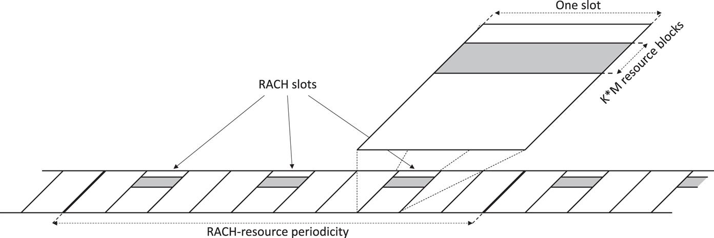
Furthermore, within these “RACH slots”, there may be multiple frequency-domain RACH occasions jointly covering K·M consecutive resource blocks where M is the preamble bandwidth measured in number of resource blocks and K is the number of frequency-domain RACH occasions.
For a given preamble type, corresponding to a certain preamble bandwidth, the overall available time/frequency RACH resource within a cell can thus be described by:
16.2.1.3 Basic Preamble Structure
Fig. 16.9 illustrates the basic structure for generating NR random-access preambles. A preamble is generated based on a length-L preamble sequence ![]() which is DFT precoded before being applied to a conventional OFDM modulator. The preamble can thus be seen as a DFTS-OFDM signal. It should be noted though that one could equally well see the preamble as a conventional OFDM signal based on a frequency-domain sequence
which is DFT precoded before being applied to a conventional OFDM modulator. The preamble can thus be seen as a DFTS-OFDM signal. It should be noted though that one could equally well see the preamble as a conventional OFDM signal based on a frequency-domain sequence ![]() being the discrete Fourier transform of the sequence
being the discrete Fourier transform of the sequence ![]() .
.

The output of the OFDM modulator is then repeated N times, after which a cyclic prefix is inserted. For the preamble, the cyclic prefix is thus not inserted per OFDM symbol but only once for the block of N repeated symbols.
Different preamble sequences can be used for the NR preambles. Similar to, for example, uplink SRS, the preamble sequences are based on Zadoff–Chu sequences [25]. As described in Section 8.3.1, for prime-length ZC sequences, which is the case for the sequences used as a basis for the NR preamble sequences, there are L–1 different sequences, with each sequence corresponding to a unique root index.
Different preamble sequences can be generated from different Zadoff–Chu sequences corresponding to different root indices. However, different preamble sequences can also be generated from different cyclic shifts of the same root sequence. As described in Section 8.3.1, such sequences are inherently orthogonal to each other. However, this orthogonality is retained at the receiver side only if the relative cyclic shift between two sequences is larger than any difference in their respective receive timing. Thus, in practice only a subset of the cyclic shifts can be used to generate different preambles, where the number of available shifts depends on the maximum timing uncertainty which, in turn, depends on, for example, the cell size. For small cell sizes a relatively large number of cyclic shifts can often be used. For larger cells, a smaller number of cyclic shifts will typically be available.
The set of cyclic shifts that can be used within a cell is given by the so-called zero-correlation zone parameter which is part of the cell random-access configuration provided within SIB1. In practice, the zero-correlation zone parameter points to a table that indicates the set of cyclic shifts available in the cell. The name “zero-correlation zone” comes from the fact that the different tables indicated by the zero-correlation-zone parameter have different distances between the cyclic shifts, thus providing larger or smaller “zones” in terms of timing error for which orthogonality (=zero correlation) is retained.
16.2.1.4 Long vs Short Preambles
NR defines two types of preambles, referred to as long preambles and short preambles, respectively. As the name suggests, the two preamble types differ in terms of the length of the preamble sequence. They also differ in the numerology (subcarrier spacing) used for the preamble transmission. The type of preamble is part of the cell random-access configuration, that is, within a cell only one type of preamble can be used for initial access.
Long preambles are based on a sequence length L=839 and a subcarrier spacing of either 1.25 kHz or 5 kHz. The long preambles thus use a numerology different from any other NR transmissions. The long preambles partly originate from the preambles used for LTE random-access [28]. Long preambles can only be used for frequency bands below 6 GHz (FR1).
As illustrated in Table 16.3 there are four different formats for the long preamble where each format corresponds to a specific numerology (1.25 kHz or 5 kHz), a specific number of repetitions (the parameter N in Fig. 16.9), and a specific length of the cyclic prefix. The preamble format is also part of the cell random-access configuration, that is, each cell is limited to a single preamble format. It could be noted that the two first formats of Table 16.3 are identical to the LTE preamble formats 0 and 2 [14].
Table 16.3
| Format | Numerology (kHz) | Number of Repetitions | CP Length (µs) | Preamble Length (Not Including CP) (µs) |
|---|---|---|---|---|
| 0 | 1.25 | 1 | ≈100 | 800 |
| 1 | 1.25 | 2 | ≈680 | 1600 |
| 2 | 1.25 | 4 | ≈15 | 3200 |
| 3 | 5 | 1 | ≈100 | 800 |

In the previous section it was described how the overall RACH resource consists of a set of slots and resource blocks in the time-domain and frequency-domain, respectively. For long preambles, which use a numerology that is different from other NR transmissions, the slot and resource block should be seen from a 15 kHz numerology point of view. In the context of long preambles, a slot thus has a length of 1 ms, while a resource-block has a bandwidth of 180 kHz. A long preamble with 1.25 kHz numerology thus occupies six resource blocks in the frequency domain, while a preamble with 5 kHz numerology occupies 24 resource blocks.
It can be observed that preamble format 1 and preamble format 2 in Table 16.3 correspond to a preamble length that exceeds a slot. This may appear to contradict the assumption of preamble transmissions taking place in RACH slots of length 1 ms as discussed in Section 16.2.1.2. However, the RACH slots only indicate the possible starting positions for preamble transmission. If a preamble transmission extends into a subsequent slot, this only implies that the scheduler needs to ensure that no other transmissions take place within the corresponding frequency-domain resources within that slot.
Short preambles are based on a sequence length L=139 and use a subcarrier spacing aligned with the normal NR subcarrier spacing. More specifically, short preambles use a subcarrier spacing of:
In the case of short preambles, the RACH resource described in Section 16.2.1.2 is based on the same numerology as the preamble. A short preamble thus always occupies 12 resource blocks in the frequency domain regardless of the preamble numerology.
Table 16.4 lists the preamble formats available for short preambles. The labels for the different preamble formats originate from the 3GPP standardization discussions during which an even larger set of preamble formats were discussed. The table assumes a preamble subcarrier spacing of 15 kHz. For other numerologies, the length of the preamble as well as the length of the cyclic prefix scale correspondingly, that is, with the inverse of the subcarrier spacing.
Table 16.4

The short preambles are, in general, shorter than the long preambles and often span only a few OFDM symbols. In most cases it is therefore possible to have multiple preamble transmissions multiplexed in time within a single RACH slot. In other words, for short preambles there may not only be multiple RACH occasions in the frequency domain but also in the time domain within a single RACH slot (see Table 16.5).
Table 16.5
| A1 | A2 | A3 | B1 | B4 | C0 | C2 | A1/B1 | A2/B2 | A3/B3 | |
|---|---|---|---|---|---|---|---|---|---|---|
| Number of RACH occasions | 6 | 3 | 2 | 7 | 1 | 7 | 2 | 7 | 3 | 2 |

It can be noted that Table 16.5 includes additional formats A1/B1, A2/B2, and A3/B3. These formats correspond to the use of a mix of the “A” and “B” formats of Table 16.4, where the A format is used for all except the last RACH occasion within a RACH slot. Note that the A and B preamble formats are identical except for a somewhat shorter cyclic prefix for the B formats.
For the same reason there are no explicit formats B2 and B3 in Table 16.5 as these formats are always used in combination with the corresponding A formats (A2 and A3) according to the above.
16.2.1.5 Beam Establishment During Initial Access
A key feature of the NR initial access is the possibility to establish a suitable beam pair already during the initial-access phase and to apply receiver-side analog beam-sweeping for the preamble reception.
This is enabled by the possibility of associating different SS-block time indices with different RACH time/frequency occasions and/or different preamble sequences. As different SS-block time indices in practice correspond to SS-block transmissions in different downlink beams, this means that the network, based on the received preamble, will be able to determine the downlink beam in which the corresponding device is located. This beam can then be used as an initial beam for subsequent downlink transmissions to the device.
Furthermore, if the association between SS-block time index and RACH occasion is such that a given time-domain RACH occasion corresponds to one specific SS-block time index, the network will know when, in time, preamble transmission from devices within a specific downlink beam will take place. Assuming beam correspondence, the network can then focus the uplink receiver beam in the corresponding direction for beam-formed preamble reception. In practice this implies that the receiver beam will be swept over the coverage area synchronized with the corresponding downlink beam sweep for the SS-block transmission.
Note that beam-sweeping for preamble transmission is only relevant when analog beam-forming is applied at the receiver side. If digital beam-forming is applied, beam-formed preamble reception can be done from multiple directions simultaneously.
To associate a certain SS-block time index with a specific random-access occasion and a specific set of preambles, the random-access configuration of the cell specifies the number of SS-block time indices per RACH time/frequency occasion. This number can be larger than one, indicating that multiple SS-block time indices correspond to a single RACH time/frequency occasion. However, it can also be smaller than one, indicating that one single SS-block time index corresponds to multiple RACH time/frequency occasions.
SS-block time indices are then associated with RACH occasions in the following order:
Fig. 16.10 exemplifies the association between SS-block time indices and RACH occasions under the following assumptions:

16.2.1.6 Preamble Power Control and Power Ramping
As discussed above, preamble transmission will take place with a relatively large uncertainty in the required preamble transmit power. Preamble transmission therefore includes a power-ramping mechanism where the preamble may be repeatedly transmitted with a transmit power that is increased between each transmission.
The device selects the initial preamble transmit power based on estimates of the downlink path loss in combination with a target received preamble power configured by the network. The path loss should be estimated based on the received power of the SS block that the device has acquired and from which it has determined the RACH resource to use for the preamble transmission. This is aligned with an assumption that if the preamble transmission is received by means of beam-forming the corresponding SS block is transmitted with a corresponding beam-shaper. If no random-access response (see below) is received within a predetermined window, the device can assume that the preamble was not correctly received by the network, most likely due to the fact that the preamble was transmitted with too low power. If this happens, the device repeats the preamble transmission with the preamble transmit power increased by a certain configurable offset. This power ramping continues until a random-access response has been received or until a configurable maximum number of retransmissions has been carried out, alternatively a configurable maximum preamble transmit power has been reached. In the two latter cases, the random-access attempt is declared as a failure.
16.2.2 Random-Access Response
Once a device has transmitted a random-access preamble, it waits for a random-access response, that is, a response from the network that it has properly received the preamble. The random-access response is transmitted as a conventional downlink PDCCH/PDSCH transmission with the corresponding PDCCH transmitted within the common search space.
The random-access response includes the following:
- • Information about the random-access preamble sequence the network detected and for which the response is valid;
- • A timing correction calculated by the network based on the preamble receive timing;
- • A scheduling grant, indicating resources the device will use for the transmission of the subsequent Message 3 (see below);
- • A temporary identity, the TC-RNTI, used for further communication between the device and the network.
If the network detects multiple random-access attempts (from different devices), the individual response messages can be combined in a single transmission. Therefore, the response message is scheduled on the DL-SCH and indicated on a PDCCH using an identity reserved for random-access response, the RA-RNTI. The use of the RA-RNTI is also necessary as a device may not have a unique identity in the form of a C-RNTI allocated. All devices that have transmitted a preamble monitor the L1/L2 control channels for random-access response within a configurable time window. The timing of the response message is not fixed in the specification in order to be able to respond to many simultaneous accesses. It also provides some flexibility in the base-station implementation. If the device does not detect a random-access response within the time window, the preamble will be retransmitted with higher power according to the preamble power ramping described above.
As long as the devices that performed random access in the same resource used different preambles, no collision will occur and from the downlink signaling it is clear to which device(s) the information is related. However, there is a certain probability of contention—that is, multiple devices using the same random-access preamble at the same time. In this case, multiple devices will react upon the same downlink response message and a collision occurs. Resolving these collisions is part of the subsequent steps, as discussed below.
Upon reception of the random-access response, the device will adjust its uplink transmission timing and continue to the third step. If contention-free random access using a dedicated preamble is used, then this is the last step of the random-access procedure as there is no need to handle contention in this case. Furthermore, the device already has a unique identity allocated in the form of a C-RNTI.
In the case of downlink beam-forming, the random-access response should follow the beam-forming used for the SS block which was acquired during the initial cell search. This is important as the device may use receive-side beam-forming and it needs to know how to direct the receiver beam. By transmitting the random-access response using the same beam as the SS block, the device knows that it can use the same receiver beam as identified during the cell search.
16.2.3 Message 3: Contention Resolution
After the second step, the uplink of the device is time synchronized. However, before user data can be transmitted to/from the device, a unique identity within the cell, the C-RNTI, must be assigned to the device (unless the device already has a C-RNTI assigned). Depending on the device state, there may also be a need for additional message exchange for setting up the connection.
In the third step, the device transmits the necessary messages to the gNB using the UL-SCH resources assigned in the random-access response in the second step.
An important part of the uplink message is the inclusion of a device identity, as this identity is used as part of the contention-resolution mechanism in the fourth step. If the device is already known by the radio-access network, that is, in RRC_CONNECTED or RRC_INACTIVE state, the already-assigned C-RNTI is used as the device identity.10 Otherwise, a core-network device identifier is used and the gNB needs to involve the core network prior to responding to the uplink message in step 4 (see below).
16.2.4 Message 4: Contention Resolution and Connection Set Up
The last step in the random-access procedure consists of a downlink message for contention resolution. Note that, from the second step, multiple devices performing simultaneous random-access attempts using the same preamble sequence in the first step listen to the same response message in the second step and therefore have the same temporary identifier. Hence, the fourth step in the random-access procedure is a contention-resolution step to ensure that a device does not incorrectly use another device’s identity. The contention resolution mechanism differs somewhat depending on whether the device already has a valid identity in the form of a C-RNTI or not. Note that the network knows from the uplink message received in step 3 whether the device has a valid C-RNTI or not.
If the device already had a C-RNTI assigned, contention resolution is handled by addressing the device on the PDCCH using the C-RNTI. Upon detection of its C-RNTI on the PDCCH the device will declare the random-access attempt successful and there is no need for contention-resolution-related information on the DL-SCH. Since the C-RNTI is unique to one device, unintended devices will ignore this PDCCH transmission.
If the device does not have a valid C-RNTI, the contention resolution message is addressed using the TC-RNTI and the associated DL-SCH contains the contention-resolution message. The device will compare the identity in the message with the identity transmitted in the third step. Only a device which observes a match between the identity received in the fourth step and the identity transmitted as part of the third step will declare the random-access procedure successful and promote the TC-RNTI from the second step to the C-RNTI. Since uplink synchronization has already been established, hybrid ARQ is applied to the downlink signaling in this step and devices with a match between the identity they transmitted in the third step and the message received in the fourth step will transmit a hybrid-ARQ acknowledgment in the uplink.
Devices that do not detect PDCCH transmission with their C-RNTI or do not find a match between the identity received in the fourth step and the respective identity transmitted as part of the third step are considered to have failed the random-access procedure and need to restart the procedure from the first step. No hybrid-ARQ feedback is transmitted from these devices. Furthermore, a device that has not received the downlink message in step 4 within a certain time from the transmission of the uplink message in step 3 will declare the random-access procedure as failed and need to restart from the first step.
16.2.5 Random Access for Supplementary Uplink
Section 7.7 discussed the concept of supplementary uplink (SUL), that is, that a downlink carrier may be associated with two uplink carriers (the non-SUL carrier and the SUL carrier), where the SUL carrier is typically located in lower-frequency bands thereby providing enhanced uplink coverage.
That a cell is an SUL cell, that is, includes a complementary SUL carrier, is indicated as part of SIB1. Before initially accessing a cell, a device will thus know if the cell to be accessed is an SUL cell or not. If the cell is an SUL cell and the device supports SUL operation for the given band combination, initial random access may be carried out using either the SUL carrier or the non-SUL uplink carrier. The cell system information provides separate RACH configurations for the SUL carrier and the non-SUL carrier and a device capable of SUL determines what carrier to use for the random access by comparing the measured RSRP of the selected SS block with a carrier-selection threshold also provided as part of the cell system information.
In practice the SUL carrier is thus selected by devices with a (downlink) pathloss to the cell that is larger than a certain value.
The device carrying out a random-access transmission will transmit the random-access message 3 on the same carrier as used for the preamble transmission.
For other scenarios when a device may do a random access, that is, for devices in connected mode, the device can be explicitly configured to use either the SUL carrier or the non-SUL carrier for the uplink random-access transmissions.