
Channel Sounding
Abstract
This chapter describes the NR support for channel sounding. Especially, it describes the specific reference signals, downlink channel-state-information reference signals (CSI-RS) and uplink sounding reference signals (SRS), on which channel sounding is typically based. It also provides an overview of the NR framework for downlink physical-layer measurements and corresponding device reporting to the network.
Keywords
Channel sounding; CSI-RS; CSI-IM; sounding-reference signals; SRS; measurements; reporting
Many transmission features in modern radio-access technologies are based on the availability of more or less detailed knowledge about different characteristics of the radio channel over which a signal is to be transmitted. This may range from rough knowledge of the radio-channel path loss for transmit-power adjustment to detailed knowledge about the channel amplitude and phase in the time, frequency, and/or spatial domain. Many transmission features will also benefit from knowledge about the interference level experienced at the receiver side.
Such knowledge about different channel characteristics can be acquired in different ways and by measurements on either the transmitter side or receiver side of a radio link. As an example, knowledge about downlink channel characteristics can be acquired by means of device measurements. The acquired information could then be reported to the network for the setting of different transmission parameters for subsequent downlink transmissions. Alternatively, if it can be assumed that the channel is reciprocal, that is, the channel characteristics of interest are the same in the downlink and uplink transmission directions, the network can, by itself, acquire knowledge about relevant downlink channel characteristics by estimating the same characteristics in the uplink direction.
The same alternatives exist when it comes to acquiring knowledge about uplink channel characteristics:
- • The network may determine the uplink characteristics of interest and either provide the information to the device or directly control subsequent uplink transmissions based on the acquired channel knowledge;
- • Assuming channel reciprocity, the device may, by itself, acquire knowledge about the relevant uplink channel characteristics by means of downlink measurements.
Regardless of the exact approach to acquire channel knowledge, there is typically a need for specific signals on which a receiver can measure/estimate channel characteristics of interest. This is often expressed as channel sounding.
This chapter will describe the NR support for such channel sounding. Especially, we will describe the specific reference signals, downlink channel-state-information reference signals (CSI-RS) and uplink sounding reference signals (SRS), on which channel sounding is typically based. We will also provide an overview of the NR framework for downlink physical-layer measurements and corresponding device reporting to the network.
8.1 Downlink Channel Sounding—CSI-RS
In the first release of LTE (release 8), channel knowledge for the downlink transmission direction was solely acquired by means of device measurements on the so-called cell-specific reference signals (CRS). The LTE CRS are transmitted over the entire carrier bandwidth within every LTE subframe of length 1 ms, and can be assumed to be transmitted over the entire cell area. Thus, a device accessing an LTE network can assume that CRS are always present and can be measured on.
In LTE release 10 the CRS were complemented by so-called CSI-RS. In contrast to CRS, the LTE CSI-RS are not necessarily transmitted continuously. Rather, an LTE device is explicitly configured to measure on a set of CSI-RS and does not make any assumptions regarding the presence of a CSI-RS unless it is explicitly configured for the device.
The origin for the introduction of CSI-RS was the extension of LTE to support spatial multiplexing with more than four layers, something which was not possible with the release-8 CRS. However, the use of CSI-RS was soon found to be an, in general, more flexible and efficient tool for channel sounding, compared to CRS. In later releases of LTE, the CSI-RS concept was further extended to also support, for example, interference estimation and multi-point transmission.
As already described, a key design principle for the development of NR has been to as much as possible avoid “always on” signals. For this reason, there are no CRS-like signals in NR. Rather, the only “always-on” NR signal is the so-called SS block (see Chapter 16) which is transmitted over a limited bandwidth and with a much larger periodicity compared to the LTE CRS. The SS block can be used for power measurements to estimate, for example, path loss and average channel quality. However, due to the limited bandwidth and low duty cycle, the SS block is not suitable for more detailed channel sounding aimed at tracking channel properties that vary rapidly in time and/or frequency.
Instead the concept of CSI-RS is reused in NR and further extended to, for example, provide support for beam management and mobility as a complement to SS block.
8.1.1 Basic CSI-RS Structure
A configured CSI-RS may correspond to up to 32 different antenna ports, each corresponding to a channel to be sounded.
In NR, a CSI-RS is always configured on a per-device basis. It is important to understand though that configuration on a per-device basis does not necessarily mean that a transmitted CSI-RS can only be used by a single device. Nothing prevents identical CSI-RS using the same set of resource elements to be separately configured for multiple devices, in practice implying that a single CS-RS is shared between the devices
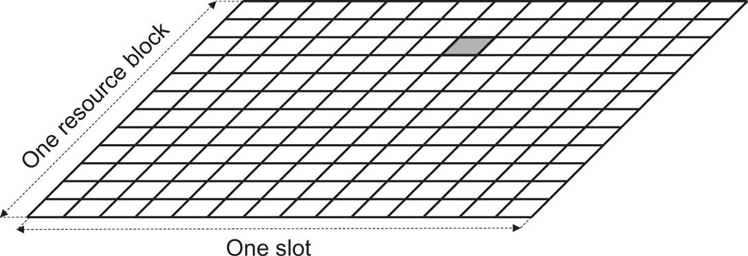
As illustrated in Fig. 8.1, a single-port CSI-RS occupies a single resource element within a block corresponding to one resource block in the frequency domain and one slot in the time domain. In principle, the CSI-RS can be configured to occur anywhere within this block although in practice there are some restrictions to avoid collisions with other downlink physical channels and signals. Especially, a device can assume that transmission of a configured CSI-RS will not collide with:
A multi-port CSI-RS can be seen as multiple orthogonally transmitted per-antenna-port CSI-RS sharing the overall set of resource elements assigned for the configured multi-port CSI-RS. In the general case, this sharing is based on a combination of:
- • Code-domain sharing (CDM), implying that different per-antenna-port CSI-RS are transmitted on the same set of resource elements with separation achieved by modulating the CSI-RS with different orthogonal patterns;
- • Frequency-domain sharing (FDM), implying that different per-antenna-port CSI-RS are transmitted on different subcarriers within an OFDM symbol;
- • Time-domain sharing (TDM), implying that different per-antenna-port CSI-RS are transmitted in different OFDM symbols within a slot.
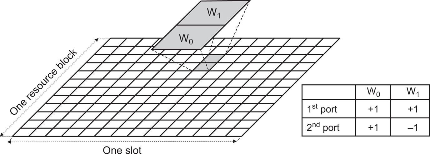
Furthermore, as illustrated in Fig. 8.2, CDM between different per-antenna-port CSI-RS can be:
- • In the frequency domain with CDM over two adjacent subcarriers (2×CDM), allowing for code-domain sharing between two per-antenna-port CSI-RS;
- • In the frequency and time domain with CDM over two adjacent subcarriers and two adjacent OFDM symbols (4×CDM), allowing for code-domain sharing between up to four per-antenna-port CSI-RS;
- • In the frequency and time domain with CDM over two adjacent subcarriers and four adjacent OFDM symbols (8×CDM), allowing for code-domain sharing between up to eight per-antenna-port CSI-RS.

The different CDM alternatives of Fig. 8.2, in combination with FDM and/or TDM, can then be used to configure different multi-port CSI-RS structures where, in general, an N-port CSI-RS occupies a total of N resource elements within an RB/slot block.1
As a first example, Fig. 8.3 illustrates how a two-port CSI-RS consists of two adjacent resource elements in the frequency domain with sharing by means of CDM. In other words, the two-port CSI-RS has a structure identical to the basic 2×CDM structure in Fig. 8.2.
In the case of CSI-RS corresponding to more than two antenna ports there is some flexibility in the sense that, for a given number of ports, there are multiple CSI-RS structures based on different combinations of CDM, TDM, and FDM.
As an example, there are three different structures for an eight-port CSI-RS (see Fig. 8.4).
- • Frequency-domain CDM over two resource elements (2×CDM) in combination with four times frequency multiplexing (left part of Fig. 8.4). The overall CSI-RS resource thus consists of eight subcarriers within the same OFDM symbol.
- • Frequency-domain CDM over two resource elements (2×CDM) in combination with frequency and time multiplexing (middle part Fig. 8.4). The overall CSI-RS resource thus consists of four subcarriers within two OFDM symbols.
- • Time/frequency-domain CDM over four resource elements (4×CDM) in combination with two times frequency multiplexing. The overall CSI-RS resource thus once again consists of four subcarriers within two OFDM symbols.

Finally, Fig. 8.5 illustrates one out of three possible structures for a 32-port CSI-RS based on a combination of 8×CDM and four times frequency multiplexing. This example also illustrates that CSI-RS antenna ports separated in the frequency domain do not necessarily have to occupy consecutive subcarriers. Likewise, CSI-RS ports separated in the time domain do not necessarily have to occupy consecutive OFDM symbols.

In the case of a multi-port CSI-RS, the association between per-port CSI-RS and port number is done first in the CDM domain, then in the frequency domain, and finally in the time domain. This can, for example, be seen from the eight-port example of Fig. 8.4 where per-port CSI-RS separated by means of CDM correspond to consecutive port numbers. Furthermore, for the FDM+TDM case (center part of Fig. 8.4), port number zero to port number three are transmitted within the same OFDM symbol, while port number four to port number seven are jointly transmitted within another OFDM symbol. Port number zero to three and port number four to seven are thus separated by means of TDM.
8.1.2 Frequency-Domain Structure of CSI-RS Configurations
A CSI-RS is configured for a given downlink bandwidth part and is then assumed to be confined within that bandwidth part and use the numerology of the bandwidth part.
The CSI-RS can be configured to cover the full bandwidth of the bandwidth part or just a fraction of the bandwidth. In the latter case, the CSI-RS bandwidth and frequency-domain starting position are provided as part of the CSI-RS configuration.
Within the configured CSI-RS bandwidth, a CSI-RS may be configured for transmission in every resource block, referred to as CSI-RS density equal to one. However, a CSI-RS may also be configured for transmission only in every second resource block, referred to as CSI-RS density equal to 1/2. In the latter case, the CSI-RS configuration includes information about the set of resource blocks (odd resource blocks or even resource blocks) within which the CSI-RS will be transmitted. CSI-RS density equal to 1/2 is not supported for CSI-RS with 4, 8, and 12 antenna ports.
There is also a possibility to configure a single-port CSI-RS with a density of 3 in which case the CSI-RS occupies three subcarriers within each resource block. This CSI-RS structure is used as part of a so-called Tracking Reference signal (TRS) (see further details in Section 8.1.7).
8.1.3 Time-Domain Property of CSI-RS Configurations
The per-resource-block CSI-RS structure outlined above describes the structure of a CSI-RS transmission, assuming the CSI-RS is actually transmitted in a given slot. In general, a CSI-RS can be configured for periodic, semi-persistent, or aperiodic transmission.
In the case of periodic CSI-RS transmission, a device can assume that a configured CSI-RS transmission occurs every Nth slot, where N ranges from as low as four, that is, CSI-RS transmissions every fourth slot, to as high as 640, that is, CSI-RS transmission only every 640th slot. In addition to the periodicity, the device is also configured with a specific slot offset for the CSI-RS transmission (see Fig. 8.6).

In the case of semi-persistent CSI-RS transmission, a certain CSI-RS periodicity and corresponding slot offset are configured in the same way as for periodic CSI-RS transmission. However, actual CSI-RS transmission can be activated/deactivated based on MAC control elements (MAC CE) (see Section 6.4.4). Once the CSI-RS transmission has been activated, the device can assume that the CSI-RS transmission will continue according to the configured periodicity until it is explicitly deactivated. Similarly, once the CSI-RS transmission has been deactivated, the device can assume that there will be no CSI-RS transmissions according to the configuration until it is explicitly re-activated.
In the case of aperiodic CSI-RS, no periodicity is configured. Rather, a device is explicitly informed (“triggered”) about each CSI-RS transmission instant by means of signaling in the DCI.
It should be mentioned that the property of periodic, semi-persistent, or aperiodic is strictly speaking not a property of the CSI-RS itself but rather the property of a CSI-RS resource set (see Section 8.1.6). As a consequence, activation/deactivation and triggering of semi-persistent and aperiodic CSI-RS, respectively, is not done for a specific CSI-RS but for the set of CSI-RS within a resource set.
8.1.4 CSI-IM—Resources for Interference Measurements
A configured CSI-RS can be used to derive information about the properties of the channel over which the CSI-RS is transmitted. A CSI-RS can also be used to estimate the interference level by subtracting the expected received signal from what is actually received on the CSI-RS resource.
However, the interference level can also be estimated from measurements on so-called CSI-IM (Interference Measurement) resources.
Fig. 8.7 illustrates the structure of a CSI-IM resource. As can be seen, there are two different CSI-IM structures, each consisting of four resource elements but with different time/frequency structures. Similar to CSI-RS, the exact location of the CSI-IM resource within the RB/slot block is flexible and part of the CSI-IM configuration.

The time-domain property of CSI-IM resources is the same as that of CSI-RS, that is, a CSI-IM resource could be periodic, semi-persistent (activation/deactivation by means of MAC CE), or aperiodic (triggered by DCI). Furthermore, for periodic and semi-persistent CSI-IM, the set of supported periodicities is the same as for CSI-RS.
In a typical case, a CSI-IM resource would correspond to resource elements where nothing is transmitted within the current cell while the activity within the CSI-IM resource in neighbor cells should correspond to normal activity of those cells. Thus, by measuring the receiver power within a CSI-IM resource, a device would get an estimate on the typical interference due to transmissions within other cells.
As there should be no transmissions on CSI-IM resources within the cell, devices should be configured with the corresponding resources as so-called ZP-CSI-RS resources (see below).
8.1.5 Zero-Power CSI-RS
The CSI-RS described above should more correctly be referred to as non-zero-power (NZP) CSI-RS to distinguish them from so-called zero-power (ZP) CSI-RS that can also be configured for a device.
If a device is scheduled for PDSCH reception on a resource that includes resource elements on which a configured CSI-RS is to be transmitted, the device can assume that the PDSCH rate matching and resource mapping avoid those resource elements. However, a device may also be scheduled for PDSCH reception on a resource that includes resource elements corresponding to a CSI-RS configured for a different device. The PDSCH must also in this case be rate matched around the resource elements used for CSI-RS. The configuration of a ZP-CSI-RS is a way to inform the device for which the PDSCH is scheduled about such rate matching.
A configured ZP-CSI-RS corresponds to a set of resource elements with the same structure as an NZP-CSI-RS. However, while a device can assume that an NZP-CI-RS is actually transmitted and is something on which a device can carry out measurements, a configured ZP-CSI-RS only indicates a set of resource blocks to which the device should assume that PDSCH is not mapped.
It should be emphasized that, despite the name, a device cannot assume that there are no transmissions (zero power) within the resource elements corresponding to a configured ZP-CSI-RS. As already mentioned, the resources corresponding to a ZP-CSI-RS may, for example, be used for transmission of NZP-CSI-RS configured for other devices. What the NR specification says is that a device cannot make any assumptions regarding transmissions on resources corresponding to a configured ZP-CSI-RS and that PDSCH transmission for the device is not mapped to resource elements corresponding to a configured ZP-CSI-RS.
8.1.6 CSI-RS Resource Sets
In addition to being configured with CSI-RS, a device can be configured with one or several CSI-RS resource sets, officially referred to as NZP-CSI-RS-ResourceSets. Each such resource set includes one or several configured CSI-RS.2 The resource set can then be used as part of report configurations describing measurements and corresponding reporting to be done by a device (see further details in Section 8.2). Alternatively, and despite the name, an NZP-CSI-RS-ResourceSet may include pointers to a set of SS blocks (see Chapter 16). This reflects the fact that some device measurements, especially measurements related to beam management and mobility, may be carried out on either CSI-RS or SS block.
Above it was described how a CSI RS could be configured for periodic, semi-persistent, or aperiodic transmission. As mentioned there, this categorization is strictly speaking not a property of the CSI-RS itself but a property of a resource set. Furthermore, all CSI-RS within a semi-persistent resource set are jointly activated/deactivated by means of a MAC CE command. Likewise, transmission of all CSI-RS within an aperiodic resource set is jointly triggered by means of DCI.
Similarly, a device may be configured with CSI-IM resource sets, each including a number of configured CSI-IM that can be jointly activated/deactivated (semi-persistent CSI-IM resource set) or triggered (aperiodic CSI-IM resource set).
8.1.7 Tracking Reference Signal (TRS)
Due to oscillator imperfections, the device must track and compensate for variations in time and frequency to successfully receive downlink transmissions. To assist the device in this task, a tracking reference signal (TRS) can be configured. The TRS is not a CSI-RS. Rather a TRS is a resource set consisting of multiple periodic NZP-CSI-RS. More specifically a TRS consists of four one-port, density-3 CSI-RS located within two consecutive slots (see Fig. 8.8). The CRS-RS within the resource set, and thus also the TRS in itself, can be configured with a periodicity of 10, 20, 40, or 80 ms. Note that the exact set of resource elements (subcarriers and OFDM symbols) used for the TRS CSI-RS may vary. There is always a four-symbol time-domain separation between the two CSI-RS within a slot though. This time domain separation sets the limit for the frequency error that can be tracked. Likewise, the frequency-domain separation (four subcarriers) sets the limit for the timing error that can be tracked.

There is also an alternative TRS structure with the same per-slot structure as the TRS structure of Fig. 8.8 but only consisting of two CSI-RS within a single slot, compared to two consecutive slots for the TRS structure in Fig. 8.8
For LTE, the CRS served the same purpose as the TRS. However, compared to the LTE CRS, the TRS implies much less overhead, only having one antenna port and only being present in two slots every TRS period.
8.1.8 Mapping to Physical Antennas
In Chapter 7, the concept of antenna ports and the relation to reference signals were discussed. A multi-port CSI-RS corresponds to a set of antenna ports and the CSI-RS can be used for sounding of the channels corresponding to those antenna ports. However, a CSI-RS port is often not mapped directly to a physical antenna, implying that the channel being sounded based on a CSI-RS is often not the actual physical radio channel. Rather, more or less any kind of (linear) transformation or spatial filtering, labeled F in Fig. 8.9, may be applied to the CSI-RS before mapping to the physical antennas. Furthermore, the number of physical antennas (N in Fig. 8.9) to which the CSI-RS is mapped may very well be larger than the number of CSI-RS ports.3 When a device does channel sounding based on the CSI-RS, neither the spatial filter F nor the N physical antennas will be explicitly visible. What the device will see is just the M “channels” corresponding to the M CSI-RS ports.

The spatial filter F may very well be different for different CSI-RS. The network could, for example, map two different configured CSI-RS such that they are beam-formed in different directions (see Fig. 8.10). To the device this will appear as two CSI-RS transmitted over two different channels, despite the fact that they are transmitted from the same set of physical antennas and are propagating via the same set of physical channels.

Although the spatial filter F is not explicitly visible to the device, the device still has to make certain assumptions regarding F. Especially, F has a strong relation to the concept of antenna ports discussed in Chapter 7. In essence one can say that two signals are transmitted from the same antenna port if they are mapped to the same set of physical antennas by means of the same transformation F.
As an example, in the case of downlink multiantenna transmission (see Chapter 11), a device may measure on a CSI-RS and report a recommended precoder matrix to the network. The network may then use the recommended precoder matrix when mapping so-called transmission layers to antenna ports. When selecting a suitable precoder matrix the device will assume that the network, if using the recommended matrix, will map the output of the precoding to the antenna ports of the CSI-RS on which the corresponding device measurements were carried out. In other words, the device will assume that the precoded signal will be mapped to the physical antennas by means of the same spatial filter F as applied to the CSI-RS.
8.2 Downlink Measurements and Reporting
An NR device can be configured to carry out different measurements, in most cases with corresponding reporting to the network. In general, such a configuration of a measurement and corresponding reporting are done by means of a report configuration, in the 3GPP specifications [15] referred to as a CSI-ReportConfig.4
Each resource configuration describes/indicates:
- • The specific quantity or set of quantities to be reported;
- • The downlink resource(s) on which measurements should be carried out in order to derive the quantity or quantities to be reported;
- • How the actual reporting is to be carried out, for example, when the reporting is to be done and what uplink physical channel to use for the reporting.
8.2.1 Report Quantity
A report configuration indicates a quantity or set of quantities that the device is supposed to report. The report could, for example, include different combinations of channel-quality indicator (CQI), rank indicator (RI), and precoder-matrix indicator (PMI), jointly referred to as channel-state information (CSI). Alternatively, the report configuration may indicate reporting of received signal strength, more formally referred to as reference-signal received power (RSRP). RSRP has historically been a key quantity to measure and report as part of higher-layer radio-resource management (RRM) and is so also for NR. However, NR also supports layer-1 reporting of RSRP, for example, as part of the support for beam management (see Chapter 12). What is then reported is more specifically referred to as L1-RSRP, reflecting the fact that the reporting does not include the more long-term (“layer-3”) filtering applied for the higher-layer RSRP reporting.
8.2.2 Measurement Resource
In addition to describing what quantity to report, a report configuration also describes the set of downlink signals or, more generally, the set of downlink resources on which measurements should be carried out in order to derive the quantity or quantities to be reported. This is done by associating the report configuration with one or several resource sets as described in Section 8.1.6.
A resource configuration is associated with at least one NZP-CSI-RS-ResourceSet to be used for measuring channel characteristics. As described in Section 8.1.6, a NZP-CSI-RS-ResourceSet may either contain a set of configured CSI-RS or a set of SS blocks. Reporting of, for example, L1-RSRP for beam management can thus be based on measurements on either a set of SS blocks or a set of CSI-RS.
Note that the resource configuration is associated with a resource set. Measurements and corresponding reporting are thus in the general case carried out on a set of CSI-RS or a set of SS blocks.
In some cases, the set will only include a single reference signal. An example of this is conventional feedback for link adaptation and multi-antenna precoding. In this case, the device would typically be configured with a resource set consisting of a single multi-port CSI-RS on which the device will carry out measurements to determine and report a combination of CQI, RI, and PMI.
On the other hand, in the case of beam management the resource set will typically consist of multiple CSI-RS, alternatively multiple SS blocks, where in practice each CSI-RS or SS block is associated with a specific beam. The device measures on the set of signals within the resource set and reports the result to the network as input to the beam-management functionality.
There are also situations when a device needs to carry out measurements without any corresponding reporting to the network. One such case is when a device should carry out measurements for receiver-side downlink beam forming. As will be described in Chapter 12, in such a case a device may measure on downlink reference signals using different receiver beams. However, the result of the measurement is not reported to the network but only used internally within the device to select a suitable receiver beam. At the same time the device needs to be configured with the reference signals to measure on. Such a configuration is also covered by report configurations for which, in this case, the quantity to be reported is defined as “None.”
8.2.3 Report Types
In addition to the quantity to report and the set of resources to measure on, the report configuration also describes when and how the reporting should be carried out.
Similar to CSI-RS transmission, device reporting can be periodic, semi-persistent, or aperiodic.
As the name suggests, periodic reporting is done with a certain configured periodicity. Periodic reporting is always done on the PUCCH physical channel. Thus, in the case of periodic reporting, the resource configuration also includes information about a periodically available PUCCH resource to be used for the reporting.
In the case of semi-persistent reporting, a device is configured with periodically occurring reporting instances in the same way as for periodic reporting. However, actual reporting can be activated and deactivated by means of MAC signaling (MAC CE).
Similar to periodic reporting, semi-persistent reporting can be done on a periodically assigned PUCCH resource. Alternatively, semi-persistent reporting can be done on a semi-persistently allocated PUSCH. The latter is typically used for larger reporting payloads.
Aperiodic reporting is explicitly triggered by means of DCI signaling, more specifically within a CSI-request field within the uplink scheduling grant (DCI format 0-1). The DCI field may consist of up to 6 bits with each configured aperiodic report associated with a specific bit combination. Thus, up to 63 different aperiodic reports can be triggered.5
Aperiodic reporting is always done on the scheduled PUSCH and thus requires an uplink scheduling grant. This is the reason why the triggering of aperiodic reporting is only included in the uplink scheduling grant and not in other DCI formats.
It should be noted that, in the case of aperiodic reporting, the report configuration could actually include multiple resource sets for channel measurements, each with its own set of reference signals (CSI-RS or SS block). Each resource set is associated with a specific value of the CSI-request field in the DCI. By means of the CSI request the network can, in this way, trigger the same type of reporting but based on different measurement resources. Note that the same could, in principle, have been done by configuring the device with multiple report configurations, where the different resource configurations would specify the same reporting configuration and report type but different measurement resources.
Periodic, semi-persistent, and aperiodic reporting should not be mixed up with periodic, semi-persistent, and aperiodic CSI-RS as described in Section 8.1.3. As an example, aperiodic reporting and semi-persistent reporting could very well be based on measurements on periodic CSI-RS. On the other hand, periodic reporting can only be based on measurements on periodic CSI-RS but not on aperiodic and semi-persistent CSI-RS. Table 8.1 summarizes the allowed combinations of reporting type (periodic, semi-persistent, and aperiodic) and resource type (periodic, semi-persistent, and aperiodic).

8.3 Uplink Channel Sounding—SRS
To enable uplink channel sounding a device can be configured for transmission of sounding reference signals (SRS). In many respects SRS can be seen as the uplink equivalence to the downlink CSI-RS in the sense that both CSI-RS and SRS are intended for channel sounding, albeit in different transmission directions. Both CSI-RS and SRS can also serve as QCL references in the sense that other physical channels can be configured to be transmitted quasi-colocated with CSI-RS and SRS, respectively. Thus, given knowledge of a suitable receiver beam for the CSI-RS/SRS, the receiver knows that the same receiver beam should be suitable also for the physical channel in question.
However, on a more detailed level, the structure of SRS is quite different from CSI-RS.
- • SRS is limited to a maximum of four antenna ports, while CSI-RS supports up to 32 antenna ports.
- • Being an uplink signal, SRS is designed to have low cubic-metric [60] enabling high device power-amplifier efficiency.
The basic time/frequency structure of an SRS is exemplified in Fig. 8.11. In the general case, an SRS spans one, two, or four consecutive OFDM symbols and is located somewhere within the last six symbols of a slot. In the frequency domain, an SRS has a so-called “comb” structure, implying that an SRS is transmitted on every Nth subcarrier where N can take the values two or four (“comb-2” and “comb-4,” respectively).

SRS transmissions from different devices can be frequency multiplexed within the same frequency range by being assigned different combs corresponding to different frequency offsets. For comb-2, that is, when SRS is transmitted on every second subcarrier, two SRS can be frequency multiplexed. In the case of comb-4, up to four SRS can be frequency multiplexed. Fig. 8.12 illustrates an example of SRS multiplexing assuming a comb-2 SRS spanning two OFDM symbols.

8.3.1 SRS Sequences and Zadoff–Chu Sequences
The sequences applied to the set of SRS resource elements are partly based on so-called Zadoff–Chu sequences [25]. Due to their specific properties, Zadoff–Chu sequences are used at several places within the NR specifications, especially in the uplink transmission direction. Zadoff–Chu sequences are also extensively used in LTE [28].
A Zadoff–Chu sequence of length M is given by the following expression:
(8.1)
As can be seen from Eq. (8.1), a Zadoff–Chu sequence has a characterizing parameter u, referred to as the root index of the Zadoff–Chu sequence. For a given sequence length M, the number of root indices generating unique Zadoff–Chu sequences equals the number of integers that are relative prime to M. For this reason, Zadoff–Chu sequences of prime length are of special interest as they maximize the number of available Zadoff–Chu sequences. More specifically, assuming the sequence length M being a prime number there are M–1 unique Zadoff–Chu sequences.
A key property of Zadoff–Chu sequences is that the discrete Fourier transform of a Zadoff–Chu sequence is also a Zadoff–Chu sequence.6 From Eq. (8.1) it is obvious that a Zadoff–Chu sequence has constant time-domain amplitude, making it good from a power-amplifier-efficiency point of view. As the Fourier transform of a Zadoff–Chu sequence is also a Zadoff–Chu sequence, there would then also be constant power in the frequency domain, that is, in addition to constant time-domain amplitude, Zadoff–Chu sequences also have flat spectra. As a flat spectrum is equivalent to zero cyclic autocorrelation for any non-zero cyclic shift, this implies that two different time-domain cyclic shifts of the same Zadoff–Chu sequence are orthogonal to each other. Note that a cyclic shift in the time domain corresponds to applying a continuous phase rotation in the frequency domain.
Although Zadoff–Chu sequences of prime length are preferred in order to maximize the number of available sequences, SRS sequences are not of prime length. The SRS sequences are therefore extended Zadoff–Chu sequences based on the longest prime-length Zadoff–Chu sequence with a length M smaller or equal to the desired SRS-sequence length. The sequence is then cyclically extended in the frequency domain up to the desired SRS sequence length. As the extension is done in the frequency domain, the extended sequence still has a constant spectrum, and thus “perfect” cyclic autocorrelation, but the time-domain amplitude will vary somewhat.
Extended Zadoff–Chu sequences will be used as SRS sequences for sequence lengths of 36 or larger, corresponding to an SRS extending over 6 and 12 resource blocks in the cases of comb-2 and comb-4, respectively. For shorter sequence lengths, special flat-spectrum sequences with good time-domain envelope properties have been found from computer search. The reason is that, for shorter sequences, there would not be a sufficient number of Zadoff–Chu sequences available.
The same principle will be used also for other cases where Zadoff–Chu sequences are used within the NR specifications, for example, for uplink DMRS (see Section 9.11.1).
8.3.2 Multiport SRS
In the case of an SRS supporting more than one antenna port, the different ports share the same set of resource elements and the same basic SRS sequence. Different phase rotations are then applied to separate the different ports as illustrated in Fig. 8.13.

 . The figure assumes a comb-4 SRS.
As described above, applying a phase rotation in the frequency domain is equivalent to applying a cyclic shift in the time domain. In the NR specification the above operation is actually referred to as “cyclic shift,” although it is mathematically described as a frequency-domain phase shift.
8.3.3 Time-Domain Structure of SRS
Similar to CSI-RS, an SRS can be configured for periodic, semi-persistent, or aperiodic transmission:
- • A periodic SRS is transmitted with a certain configured periodicity and a certain configured slot offset within that periodicity;
- • A semi-persistent SRS has a configured periodicity and slot offset in the same way as a periodic SRS. However, actual SRS transmission according to the configured periodicity and slot offset is activated and deactivated by means of MAC CE signaling;
- • An aperiodic SRS is only transmitted when explicitly triggered by means of DCI.
It should be pointed out that, similar to CSI-RSI, activation/deactivation and triggering for semi-persistent and aperiodic SRS, respectively, is actually not done for a specific SRS but rather done for a so-called SRS resource set which, in the general case, included multiple SRS (see below).
8.3.4 SRS Resource Sets
Similar to CSI-RS, a device can be configured with one or several SRS resource sets, where each resource set includes one or several configured SRS. As described above, a SRS can be configured for periodic, semi-persistent, or aperiodic transmission. All SRS included within a configured SRS resource set have to be of the same type. In other words, periodic, semi-persistent, or aperiodic transmission can also be seen as a property of an SRS resource set.
A device can be configured with multiple SRS resource sets that can be used for different purposes, including both downlink and uplink multiantenna precoding and downlink and uplink beam management.
The transmission of aperiodic SRS, or more accurately, transmission of the set of configured SRS included in an aperiodic SRS resource set, is triggered by DCI. More specifically, DCI format 0-1 (uplink scheduling grant) and DCI format 1-1 (downlink scheduling assignment) include a 2-bit SRS-request that can trigger the transmission of one out of three different aperiodic SRS resource sets configured for the device (the fourth bit combination corresponds to “no triggering”).
8.3.5 Mapping to Physical Antennas
Similar to CSI-RS, SRS ports are often not mapped directly to the device physical antennas but via some spatial filter F that maps M SRS ports to N physical channels (see Fig. 8.14).

In order to provide connectivity regardless of the rotational direction of the device, NR devices supporting high-frequency operation will typically include multiple antenna panels pointing in different directions. The mapping of SRS to one such panel is an example of a transformation F from SRS antenna ports to the set of physical antennas. Transmission from different panels will then correspond to different spatial filters F as illustrated in Fig. 8.15.

Similar to the downlink, the spatial filtering F has a real impact despite the fact that it is never explicitly visible to the network receiver but just seen as an integrated part of the overall channel. As an example, the network may sound the channel based on a device-transmitted SRS and then decide on a precoder matrix that the device should use for uplink transmission. The device is then assumed to use that precoder matrix in combination with the spatial filter F applied to the SRS. In other cases, a device may be explicitly scheduled for data transmission using the antenna ports defined by a certain SRS. In practice this implies that the device is assumed to transmit using the same spatial F that has been used for the SRS transmission. In practice, this may imply that the device should transmit using the same beam or panel that has been used for the SRS transmission.