


Availability in the zSeries and z9 environment
In this chapter we give you an overview of system availability in the zSeries environment. We discuss the following topics:
•High availability
•Continuous operation
•Continuous availability
We discuss what has to be done to plan and implement a continuous availability solution and how the IBM zSeries platform and its components can be used to accomplish this.
Even though you can use the general guidelines for other platforms also, we focus here on the zSeries platform only.
8.1 System availability terminology

Figure 8-1 System availability terminology
High availability
The term high availability means the ability of a complex system, its subsystems, and its applications (independent of its complexity) to provide service to its users during defined service periods, without errors (hardware, software, or human) that might cause disruption of such services. In other words, no unplanned outages due to errors should occur. Many installations consider availability of 99.7 percent as an accepted minimum level for highly available systems. Service periods are normally defined in service level agreements (SLAs), a contract between the end users and the service providers (for example, a data center).
Continuous operation
Continuous operation means the ability of a complex system, its subsystems, and its applications to provide service to its users at any time, even when a partial planned outage is performed. This partial planned outage is necessary to perform maintenance for the system (programs) and its data. At first view it seems to be very difficult to perform change and maintenance activities on a system while keeping it in continuous operation mode.
Continuous availability
Continuous availability (CA) refers to the ability of a complex system, its subsystems, and its applications to provide both high availability and continuous operation at the same time. In other words, continuous availability is going to produce the famous “24 by 7.” You can imagine that it might be difficult to approach this level of operation because hardware and software components are not entirely free of errors and maintenance, and there are also many changes in the computing environment. Therefore, it is important to make use of hardware, software, and operational procedures that hide outages from the end user. Thus it is essential for many zSeries processors and z/OS that changes and maintenance be possible while the systems are up and running. These continuous availability attributes eliminate the need for switching the workload to an alternate system to perform changes and maintenance on the primary system.
The lack of continuous availability is caused by the existence of single points of failure (SPOF) in the elements composing the computational environment. The technique to fight back the SPOFs is redundancy, which implies additional capacity. One type of redundancy is cloning. One example of cloning is all the z/OSs in a Parallel Sysplex fully exploiting data and program sharing. If one z/OS has a planned or unplanned outage, the other z/OSs execute the arriving transactions, because due to cloning the functionality is the same.
However, the most serious problem affecting CA is the multiple concurrent failures scenario. All the redundancy that we can put together might not be enough to maintain the 24 by 7 goal. This scenario belongs in the realm of disaster recovery, where the target is just to reduce the mean time to repair (MTTR).
An example of multiple concurrent failures could be the outage of the primary sysplex couple data set together with one z/OS. In this case, because of integrity issues, all the z/OSs need to be IPLed again despite the existence of an alternate sysplex couple data set.
8.2 Continuous availability as a target

Figure 8-2 Continuous availability as a target
Continuous availability as a target
Figure 8-2 shows the dependencies between the three terms we introduced. A system can be either highly available or continuously operational, or it can be a composition of both. In the third case it will achieve the highest level. But before you decide to make a system continuously available, you first have to determine what your business requirements are. Then you will have to take further steps in the implementation of your solution. We discuss these next.
8.3 A structured approach to continuous availability design
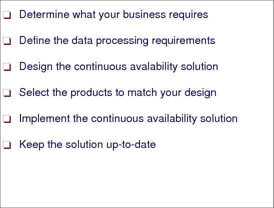
Determine what your business requires
First you have to determine which of the aspects of continuous availability are required for which business processes. In today’s world a huge number of business processes depend on information technology and available resources. That means if an outage occurs, they might come to a complete standstill, which means loss of business and revenue. The impact of such outages has to be evaluated by performing a business impact analysis.
Define the data processing requirements
Once you have established your business requirements, you must translate them into data processing terms for use during system design. The results of these data processing requirements are service level objectives.
Design the continuous availability solution
After the data processing requirements have been established and agreed upon, you must design a technical solution that will satisfy these requirements. Designing means that you define the characteristics and major elements of your solution. It is a generic description of hardware, software, and systems management functions required for the desired level of availability. Very often, you can estimate the cost of your solution only after you have done a high-level design.
Select the products to match your design
Once you have completed the design for your availability solution, you can then select the appropriate zSeries products. These products will, of course, have a major influence on the cost of your overall solution.
Implement the continuous availability solution
You are now ready to implement your availability solution. You have to install the required zSeries hardware and software components, introduce systems management procedures, and develop appropriate system documentation.
Keep the solution up-to-date
After implementing the continuous availability solution, it is very important that you put procedures in place to ensure that your solution remains viable regardless of changes in your computing environment. You do this through systems management procedures that help you define, verify or implement availability measures at each system change or introduction of new applications.
|
Tip: Today it is very common to align the systems management procedures with ITIL® (IT Infrastructure Library®). ITIL in a sense is just a new name for the traditional systems management tasks. We recommend that you get familiar with the concepts of this most widely accepted approach to IT service management. It is not zSeries specific, but it is used on this platform. For more information about ITIL, refer to:
|
8.4 Decision criteria for a continuous availability design
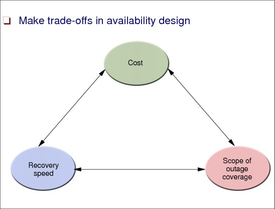
Figure 8-4 Decision criteria for a continuous availability design
Make trade-offs in availability design
Although you want to develop an availability solution that exactly matches the requirements of your business, you must be aware that some requirements are trade-offs, or are even mutually exclusive. In addition, the more stringent the requirements are, the higher the cost of the designed solution will be.
You need to ask the following questions:
•Cost - What will the cost of the targeted solution be?
•Recovery speed - How fast must the recovery from an outage be accomplished? How long can a downtime last without affecting the critical business?
•Scope of outage coverage - What type of outage does the designed solution cover?
8.5 Hardware - Environmental aspects

Figure 8-5 Hardware - Environmental aspects
Power
There are two basic requirements for your power infrastructure:
•The normal main power supply should be as reliable and robust as possible, with a minimal number of outages.
•The infrastructure you provide must be able to keep at least your essential equipment up and running during any power interruption. There are no-breaks options covering such requirements.
In order to satisfy these requirements, the following has to be carefully considered:
•Ensure that critical components have redundant power connections and that these components are actually connected to redundant power sources.
•Provide an uninterruptable or redundant power supply for critical components.
•Establish procedures to test failover to the redundant power source on a regular basis.
Cooling
You have to provide sufficient cooling capacity and redundancy to ensure that environment conditions can be maintained in case of an equipment failure. Even though modern mainframe equipment no longer requires water cooling, a temperature-controlled environment is still required.
Therefore, make sure that the cooling capacity is sufficient and install a redundant cooling unit that can take over in the event of equipment failure. Establish procedures to ensure speedy takeover in the event of an environmental failure.
Geographic location
When deciding where to place a data center, you should also consider the following:
•Neighboring establishments. For example, a chemical leakage at an adjoining plant can mean that physical access to your installation is denied, even if there is nothing wrong with your site.
•At a minimum, you should ensure that all your equipment can be operated, monitored, and controlled from a remote location that is distant enough so that access will not be denied to your facility in case of a local disaster.
•Avoid, if possible, choosing a place with intense seismic activity.
Physical security
There has always been a need for strict security at computer sites because of the value and sensitivity of the equipment there. However, in the modern world, there is the additional risk of terrorism.It is extremely expensive, maybe even not possible, to protect a computer installation from all potential forms of attack.
The best line of defense is to use remote copy technology and GDPS (discussed in detail in Chapter 7, “Geographically Dispersed Parallel Sysplex” on page 293) to mirror all data to a remote site that can take over operations at very short notice in the event of a disaster impacting one of the sites. While it may not be possible to have a 100% secure primary site, the chances of losing two adequately equipped and protected sites should be low enough to constitute an acceptable business risk.
Certainly one of the ways of improving security is through anonymity and protection of confidential information. Many companies will no longer divulge the location of their computer facilities. Another simple recommendation is to prevent removal from the site of disks that are assumed to be defective (as customer engineers from DASD storage controller vendors might try to do).
Automation
Nearly all hardware is designed so that some form of message or alert is given in case of a problem or failure. However, there is no point issuing these alerts unless they reach the person responsible for that piece of equipment. It is not unknown for a redundant piece of hardware (like a Sysplex Timer, for example), to be broken for months without anyone noticing.
Therefore, automation should be put in place to trap and forward such messages and alerts to the responsible party, and also to at least one other individual (to avoid single points of failure).
Physical configuration control
In order to ensure that devices are actually connected according to your plans—and most especially to ensure that devices and cables can be easily identified in case of a problem—it is vital that all equipment and cables are clearly labelled. Ideally, an integrated cable management system is employed. An example is Hardware Configuration Management (HCM), an optional component of z/OS, which lets you control not only your hardware devices, but also the cables used to connect them, cable cabinets, and so on.
8.6 Hardware - Central processing complexes

Figure 8-6 Hardware - Central processing complexes
Number of CPCs
In order to avoid a single point of failure, you should always configure a minimum of two central processing complexes (CPCs), regardless of the fact that a single CPC might be able to provide sufficient processing power to handle the whole workload. Even though the reliability of CPCs is increasing all the time, there are still a few planned changes that require a shutdown or Power-On-Reset of a whole CPC, so having at least two CPCs allows you to maintain application availability at all times.
For availability reasons, the CPCs should be placed in different locations, or if in the same location, at least separated from each other by a fireproof/flood-proof wall. When placing CPCs in different locations, it is important to be aware of the distance limitations of CF links, ESCON channels, Sysplex Timer links, and so on. Also be aware of the performance impact the distance can have on your applications.
Each CPC should have at least one, and preferably two, LPs that participate in the production sysplex. By doing this, it is possible to lose one CPC and still have the possibility to keep your applications available. By having two production LPs on each CPC, you still have access to the MIPS of that CPC even if you need to shut down one of those LPs.
Non-disruptive upgrades
CP, IFL, ICF, and/or zAAP processors can be concurrently added to a z9 CPC if there are spare PUs available on any installed book. The number of zAAPs cannot exceed the number of CPs plus unassigned CPs on a z9 CPC.
Additional books can also be installed concurrently, allowing further processor upgrades. A processor upgrade cannot be performed when CBU or On/Off CoD is activated. Concurrent upgrades are not supported with CPs defined as additional SAPs. If reserved processors are defined to a logical partition, then z/OS, OS/390, and z/VM operating system images can dynamically configure more processors online, allowing nondisruptive processor upgrades. The Coupling Facility Control Code (CFCC) can also configure more processors online to Coupling Facility logical partitions using the CFCC image operations panel.
Concurrent upgrades
The z9 CPCs have the capability of concurrent upgrades, providing additional capacity with no server outage. In most cases, with prior planning and operating system support, a concurrent upgrade can also be nondisruptive, that is, without system outage (Power-on Resets (PORs), logical partition deactivations, and IPLs do not have to take place).
Given today’s business environment, the benefits of the concurrent capacity growth capabilities provided by z9 servers are plentiful, and include:
•Enabling exploitation of new business opportunities
•Supporting the growth of e-business environments
•Managing the risk of volatile, high-growth, and high-volume applications
•Supporting 24x365 application availability
•Enabling capacity growth during “lock down” periods
This capability is based on the flexibility of the z9 system design and structure, which allows configuration control by the Licensed Internal Code (LIC) and concurrent hardware installation.
Licensed Internal Code (LIC)-based upgrades
The LIC - Configuration Control (LIC-CC) provides for server upgrade with no hardware changes by enabling the activation of additional, previously installed capacity. Concurrent upgrades via LIC-CC can be done for:
•Processors (CPs, IFLs, ICFs, and zAAPs) - Requires available spare PUs on installed books.
•Memory - Requires available capacity on installed memory cards.
•I/O cards ports (ESCON channels and ISC-3 links) - Requires available ports on installed I/O cards.
Concurrent hardware installation upgrades
Configuration upgrades can also be concurrent by installing additional:
•Books (which contain processors, memory, and STIs) - Requires available book slots in the installed CEC cage.
•I/O cards - Requires available slots on installed I/O cages. I/O cages cannot be installed concurrently.
The concurrent upgrade capability can be better exploited when a future target configuration is considered in the initial configuration. Using this Plan Ahead concept, the required number of I/O cages for concurrent upgrades, up to the target configuration, can be included in the z9 CPC initial configuration.
Capacity Upgrade on Demand
Capacity Upgrade on Demand (CUoD) is a function available on z9 CPCs that enables concurrent and permanent capacity growth.
The CUoD function is based on the Configuration Reporting Architecture, which provides detailed information on system-wide changes, such as the number of configured Processor Units, system serial numbers, and other information.
CUoD provides the ability to concurrently add processors (CPs, IFLs, ICFs, and zAAPs), memory capacity, and I/O ports. The concurrent upgrade can be done by Licensed Internal Code Configuration Control (LIC-CC) only or also by installing additional books and/or I/O cards.
CUoD is ordered as a “normal” upgrade, also known as Miscellaneous Equipment Specification (MES). CUoD does not require any special contract, but requires IBM service personnel for the upgrade. In most cases, a very short period of time is required for the IBM personnel to install the LIC-CC and complete the upgrade.
To better exploit the CUoD function, an initial configuration should be carefully planned to allow a concurrent upgrade up to a target configuration. You need to consider planning, positioning, and other issues to allow a CUoD nondisruptive upgrade. By planning ahead, it is possible to enable nondisruptive capacity and I/O growth for the z990 with no system power down and no associated POR or IPLs.
The Plan Ahead feature involves pre-installation of additional I/O cages, as it is not possible to install an I/O cage concurrently. CUoD for processors can add, concurrently, more CPs, IFLs, ICFs, and zAAPs to a z9 CPC by assigning available spare PUs via LIC-CC. Depending on the quantity of the additional CPs, IFLs, ICFs, and zAAPs in the upgrade, additional books may be required and can be concurrently installed before the LIC-CC enablement.
Capacity Backup
Capacity BackUp (CBU) is offered with the z9 CPC servers to provide reserved emergency backup processor capacity for unplanned situations where customers have lost capacity in another part of their establishment and want to recover by adding the reserved capacity on a designated z9 CPC.
CBU is the quick, temporary activation of Central Processors (CPs), up to 90 days, in the face of a loss of customer processing capacity due to an emergency or disaster/recovery situation.
When the CBU activated capacity is no longer required, its removal is nondisruptive. If CBU is activated on a z9 CPC, other hardware upgrades/MES are restricted. With the exception of memory and channels, LIC-CC enabled features, such as CPs, ICFs, IFLs, and zAAPs, can be ordered, but not enabled until the CBU upgrade is deactivated.
8.7 Hardware - coupling facilities

Figure 8-7 Hardware - coupling facilities
Coupling facility capacity
In order to be able to deliver acceptable response times, you must have enough capacity in your CFs. In addition to CF PU utilization, you must also consider response times. It is possible for CF PU utilization to be low, but CF response times to be so long that the cost of using the CF becomes unacceptable (this is especially the case if there is a large disparity in speed between the CF CPC and the CPCs the z/OSs are running on).
Failure isolation
One of the most important characteristics of a CF is its location in relation to the z/OS systems that are connected to it. There are some advantages to it being in a stand-alone processor. However, the most important question is whether a single failure can impact both the CF and one or more z/OSs connected to it. A CF in a CPC where none of the other images in that CPC are connected to that CF can provide nearly as good availability as one running in a stand-alone processor.
Coupling facility failure recovery
CFs are different from z/OS LPs in that if a CF fails, it is possible that the CF contents can be re-created in an alternate CF, allowing operations to continue with just a pause in processing.
When planning for CF recovery, you need to consider whether the structures in the failed CF support recovery from a CF failure, and whether the remaining CFs have sufficient capacity to take over from the failed CF.
Number of coupling facilities
As a general rule, you should always have at least two CFs in a production Parallel Sysplex. There are a small number of structures whose loss does not have a significant impact on the sysplex (OPERLOG and LOGREC are two examples), but in most cases, the loss of a structure will have some negative or disabling effect on the sysplex connected systems.
As a result, it is vital that there always be an alternative CF available for a structure to rebuild into in the case of a planned or unplanned CF outage. This is why we recommend that every Parallel Sysplex has at least two CFs, even if you are only exploiting the Resource Sharing capability of the sysplex.
Some larger customers, especially those doing extensive exploitation of data sharing and those that have very high availability requirements are now starting to deploy three CFs in their production Parallel Sysplexes. This provides greater capacity to cope with unexpected workload spikes and rebuild flexibility, and also ensures that there is still no single point of failure, even if one CF is unavailable for some reason.
CFCC level considerations
The level of Coupling Facility Control Code (CFCC) running in your CF determines the functions that CF supports. In 1.13, “Coupling facility LPARs and CFCC code” on page 23 you can see a table with functions and their integration into a specific CFCC level. Prior to z990, CF level upgrades were always disruptive. Therefore, make sure to plan all CF level upgrades well in advance. In fact, it is a good idea to upgrade to the latest CF level available on your CPCs as they become available and as you get the opportunity to do a Power-On-Reset. This ensures that should a need arise for the functionality in that CF level, there is a good chance that it will already be installed and available.
Coupling facility maintenance procedures
There are various approaches for maintenance of coupling facilities:
•Some customers maintain three CFRM policies: One that contains both CFs, one that contains just one CF, and a third that contains just the other. To empty a CF, they switch to the policy containing just the CF that will remain in service, and then rebuild all the structures that now have a POLICY CHANGE PENDING status.
•Another method is to simply issue a SETXCF START,RB,CFNM=cfname,LOC=OTHER command for the CF that is to be emptied. If you do this, you will need to move any XCF structures out of the CF with individual SETXCF START,RB commands.
Coupling facility volatility
An exploiter application that is using the coupling facility might require nonvolatility of the coupling facility storage. Depending on the CPC on which the coupling facility is defined, you might have to provide a backup power supply to make the contents of coupling facility storage nonvolatile across utility power failures. PR/SM Planning Guide describes the processor requirements for coupling facility nonvolatility and the coupling facility control code MODE command in HMC. This command must be set so that applications using the coupling facility can monitor its nonvolatility status. Coupling facilities also have the capability of a power save state for preserving coupling facility storage. Power save state allows the coupling facility storage to be maintained during a utility power outage so that the structures in the storage remain intact. In the server, other LPs that are not coupling facilities are automatically system-reset when the power is lost. The PR/SM Planning Guide provides two scenarios that describe recovery actions in a Parallel Sysplex environment with a coupling facility enabled for the power save state.
8.8 Hardware - switches

Figure 8-8 Hardware - switches
ESCON Directors
The ESCON Director (IBM 9032-5) offers any-to-any connectivity for its full range of 248 ESCON ports. All ESCON ports support attachment of channels, control units, serial CTCs, converters (for attachment to convertors two 9032-5 ESCON ports are defined as having a dedicated connection) and other ESCON Directors.
The 9032-5 ESCON also supports up to 16 FICON Bridge cards. These cards convert FICON protocol to ESCON because of the existence of old controllers. Each FICON Bridge card can support 1 FICON port. The internal matrix connections from the FICON Bridge card can be to any ESCON port that logically connects to a ESCON interface control unit or an ESCON serial CTC channels. The external connection to the FICON Bridge card can only be to a S/390 FICON channel in FCV mode. FCV mode is FICON ConVersion mode.
The 9032-5 supports both LED and XDF ESCON ports.
FICON Switches
FICON channels implement the switched point-to-point topology by using FICON switches (F_Ports) to connect FICON channels (N_Ports) to control unit FICON adapters (N_Ports). These connections are established as the server FICON channel Login Link Service FLOGI discovers that its N_Port is connected to a F_Port (switch port) and the control unit FICON port Login Link Service, FLOGI, discovers that its N_Port is also connected to an F_Port (switch port).
This topology allows a much more flexible and dynamic environment and is required to exploit the I/O frame multiplexing capability of FICON channels. All FICON switch connections are dynamic. So static connections, which are possible in an ESCON Director, are not supported in a FICON Director. FICON protocol initially keeps its channel-to-CU path definition approach, which provides controlled access. It does not use a fabric port address discovery (N_Port) approach and requires a known fabric port address, which is the switch destination port.
Switch cascading is a switched point-to-point configuration with more than one dynamic connection in the path. Note that ESCON switched point-to-point configurations also do not support switch cascading, as one of the two possible switch connections must be static. This is a switch chaining extension for ESCON devices. FICON channels do not require any repeater or switch to reach up to 10 km (20 km with RPQ). So initially, only one FICON switch can be used between a FICON channel and a FICON control unit adapter.
FICON support of Cascading Directors is a switched point-to-point configuration with only two switches in the path. Therefore, all the rules discussed for FICON switched point-to-point also apply for the FICON support for cascaded Directors. FICON channels implement the FICON support for cascaded switches topology by using two dynamic FICON switches (F_Ports) to connect FICON channels (N_Ports) to control unit FICON adapters (N_Ports). These connections are established as the server FICON channel Login Link Service FLOGI to the entry switch of the defined fabric and discovers that its N_Port is connected to an F_Port (switch port) and the control unit FICON port Login Link Service, FLOGI, discovers that its N_Port is also connected to an F_Port (switch port) to the cascaded switch of the fabric.
A connection between both switches in the fabric is performed in such a way that a switch’s F_Port (in the entry switch) discovers that it is connected to another F_Port in the other switch (the cascaded switch). The result is that both ports will change their role to support the E_Port functions and form the Inter-Switch Link (ISL) connection.
More than one ISL can be established between both switches in the FICON-supported cascaded director environment. In that case balancing will be done between the multiple ISLs. Since balancing methodologies are vendor-specific, refer to the FICON Director vendor documentation for details.
To ensure data security in the extended environment, both switches have to be in a High Integrity Fabric, which is created by configuring Fabric Binding and Insistent Domain ID in the FC switches. This is checked during channel initialization time. If a 2-byte link address is found for a CU connected to a particular channel, a Query Security Attribute (QSA) is sent to the switch to check whether both are in a high integrity fabric. If it is found, normal channel initialization continues. If the high integrity fabric is not present, no further action is performed.
8.9 Hardware - DASD and other devices
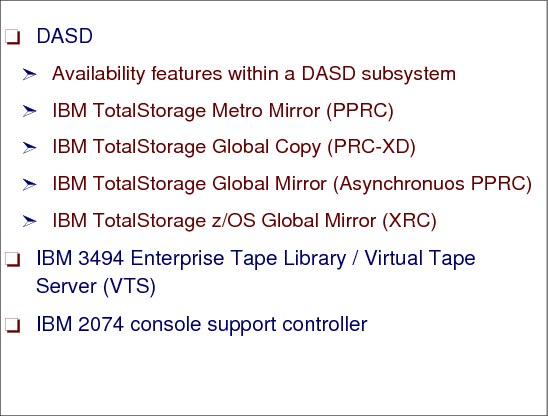
Figure 8-9 Hardware - DASD and other devices
DASD
In a continuous availability environment you must configure a DASD subsystem in two ways:
•Create a configuration that will survive the loss of any single component within the subsystem.
•Configure your storage subsystem such that your data can survive, or at least recover from, a complete loss of the whole subsystem.
Features in today’s storage subsystems like the IBM DS8000, DS6000™ or Enterprise Storage Server (ESS) support this. Some of them are standard features, some are optional, and some are not available on all storage subsystem types. They are:
•Independent dual power feeds
•N+1 power supply technology/hot swappable power supplies, fans
•N+1 cooling
•Battery backup
•Non-Volatile Subsystem cache, to protect writes that have not been hardened to DASD yet
•Nondisruptive maintenance
•Concurrent LIC activation
•Concurrent repair and replace actions
•RAID architecture
•Redundant microprocessors and data paths
•Concurrent upgrade support (that is, ability to add disks while subsystem is online)
•Redundant shared memory
•Spare disk drives
•FlashCopy/SnapShot/Concurrent copy
•Remote Copy (PPRC and/or XRC)
•HyperSwap support (GDPS/PPRC function)
IBM TotalStorage Metro Mirror (Synchronous PPRC)
Metro Mirror is a remote-mirroring technique for all zSeries and z9 servers. It is designed to constantly maintain an up-to-date copy of the local application data at a remote site that is within the metropolitan area (typically up to 20 km away using DWDM). With synchronous mirroring techniques, data currency is maintained between sites, though the distance can have some impact on performance. Metro Mirror is used primarily as part of a business continuance solution for protecting data against disk storage system loss or complete site failure.
IBM TotalStorage Global Copy (Asynchronous PPRC-XD)
Global Copy is an asynchronous remote copy function for z/OS systems for longer distances than are possible with Metro Mirror. With Global Copy, write operations complete on the primary storage system before they are received by the secondary system. This capability is designed to prevent the primary system’s performance from being affected by wait-time from writes on the secondary system. Therefore, the primary and secondary copies can be separated by any distance. This function is appropriate for remote data migration, off-site backups, and transmission of inactive database logs at virtually unlimited distances.
IBM TotalStorage Global Mirror (Asynchronous PPRC)
Global Mirror copying provides a two-site extended distance remote mirroring function for z/OS and servers. With Global Mirror, the data that the host writes to the storage unit at the local site is asynchronously shadowed to the storage unit at the remote site. A consistent copy of the data is then automatically maintained on the storage unit at the remote site. This two site data mirroring function is designed to provide a high-performance, cost-effective global distance data replication and disaster recovery solution.
IBM TotalStorage z/OS Global Mirror (Extended Remote Copy XRC)
z/OS Global Mirror is a remote data mirroring function available for z/OS. It maintains a copy of the data asynchronously at a remote location over unlimited distances. z/OS Global Mirror is well suited for large zSeries server workloads and can be used for business continuance solutions, workload movement and data migration.
IBM 3494 Enterprise Tape Library/Virtual Tape Server (VTS)
The IBM TotalStorage 3494 tape library is an excellent solution for large storage requirements. The 3494 tape library consists of individual frame units for modular expansion that provides a wide range of configurations. This flexibility enables organizations to start small and grow in an affordable and incremental manner without disregarding the aspects of availability.
•When configuring your Tape Library or VTS for high availability, make sure you configure enough paths to the device. If possible, configure paths through different ESCON Directors. If running in an LPAR environment, use EMIF to reduce the number of required channels, but be aware of implications of using EMIF: if one channel fails, it could affect more than one LPAR.
•When installing a 3494 Tape Library, plan for expansion of the tape library with additional frames. Plan to use the High Availability feature of 3494 Tape Library.
IBM 2074 console support controller
The IBM 2074 is a replacement for local, non-SNA 3174 Control Units. The 2074 is a shared control unit that can be used simultaneously by multiple LPARs, using EMIF-capable channels. For example, a single 2074 might provide z/OS consoles (and TSO sessions) for ten LPARs. The LPARs might be in a single zSeries system or spread across multiple zSeries systems. Configuring a high-availability environment with 2074s would mean that you need at least two 2074s. You can find more information about the functions of a 2074 in 5.5, “2074 console support controller configuration” on page 245.
..................Content has been hidden....................
You can't read the all page of ebook, please click here login for view all page.