


Resource Recovery Services (RRS)
Many computer resources are so critical to a company’s work that the integrity of these resources must be guaranteed. If changes to the data in the resources are corrupted by a hardware or software failure, human error, or a catastrophe, the computer must be able to restore the data. These critical resources are called protected resources or, sometimes, recoverable resources.
Resource recovery is the protection of the resources. Resource recovery consists of the protocols and program interfaces that allow an application program to make consistent changes to multiple protected resources.
This chapter gives an introduction to the function of Resource Recovery Service (RRS) in a z/OS system. RRS provides a global syncpoint manager that any resource manager on z/OS can exploit. RRS is increasingly becoming a prerequisite for new resource managers, and for new capabilities in existing resource managers. Rather than having to implement their own two-phase commit protocol, these products can use the support provided by RRS. However, as more transaction managers have become RRS resource managers, and as the complexity of the exchanges of transactional data increases, more and more systems and application programmers will need to use RRS. This chapter covers the following topics:
•Introduction to Resource Recovery Services (RRS)
•Two-phase commit protocol
•Two-phase commit process
•Two-phase backout process
•Resource Manager
•Setting up RRS in the z/OS system
•Exploiters of RRS
•RRS commands
|
Note: More information about RRS is available in:
•Systems Programmer’s Guide to Resource Recovery Services (RRS), SG24-6980
•z/OS MVS Programming: Resource Recovery, SA22-7616
|
3.1 Introduction to Resource Recovery Services (RRS)

Figure 3-1 Introduction to Resource Recovery Services (RRS)
Introduction to Resource Recovery Services (RRS)
To add the RRS panels as an option on your ISPF primary panel, you should make a copy of the ISPF primary option menu – ISR@PRIM. Then, add the following information to the processing section of the panel:
RRS,'PANEL(ATRFPCMN) NEWAPPL(RRSP)'
Make sure you concatenate the library containing your customized primary panel before any others in your logon procedure or CLIST.
|
Note: There is an alternative way to access the RRS panels from the ISPF Main Menu. You can do this by using the following steps:
1. Go to your ISPF Main Menu and choose option 7.1 to perform dialog testing:
Option ===> 7.1
2. After the ISPF Dialogue Test Menu is displayed, invoke the selection panel by doing the following:
a. Put atrfpcmn in the panel option.
b. Use atrk as the ID.
c. Press Enter to display the RRS main panel.
|
RRS exploiters
There are many exploiters of Resource Recovery Services (RRS), and each has its own resource manager (RM). With the increasing number of resource managers now available on z/OS, there was clearly a need for a general syncpoint manager on z/OS that any resource manager could exploit. This is the role of RRS, a component of z/OS. It enables transactions to update protected resources managed by many resource managers. Applications must be sure that changes to data have been made or backed out and so the applications must access this data via the RM.
Figure 3-1 shows how RRS acts as a syncpoint manager in the z/OS system.
RRS functions
RRS coordinates the two-phase commit process, which is a protocol used by the RM exploiter. RRS runs in its own address space and normally is started at IPL time, but if RRS suffers problems it is restartable. RRS is also responsible for the association between a Unit of Recovery (UR) and a Work Context. RRS builds this UR each time an RM wants to make a transaction. A UR is the base element of a transaction. A Work Context is a representation of a work request (transaction) and may consist of a number of Units of Recovery. RRS is an exploiter of the System Logger and stores the logs with logger functions in the coupling facility.
The advantage of using RRS is to ensure data integrity for all applications that exploit RRS because if a transaction fails, RRS notifies the resource managers.
3.2 Two-phase commit protocol
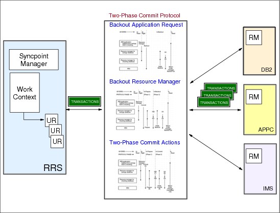
Figure 3-2 Two-phase commit protocol
Two-phase commit protocol
RRS is a syncpoint manager that provides services to each RM and informs the RM about any changes. An exit manager is an authorized program that gives control to an RM in case there is an event that should be triggered. RRS only checks that each event is processed in the right sequence, and in case there are problems RRS informs the RM. This means that RRS itself does not perform any actions on a DB2 database or back out changes to an IMS database. Instead, RRS triggers resource manager-supplied exits based on certain events. An application can request RRS to commit a unit of recovery (UR), and RRS then invokes the commit exits for all the resource managers involved in the UR.
Over the years resource managers on z/OS have evolved to provide two-phase commit processing between them. When the application is ready to commit or back out its changes, the application invokes RRS to begin the two-phase commit protocol.
RRS supports the two-phase commit protocol as shown in Figure 3-2. The two-phase commit protocol is a set of actions used to make sure that an application program either makes all changes to the resources represented by a single unit of recovery (UR), or makes no changes at all. This protocol verifies that either all changes or no changes are applied even if one of the elements (such as the application, the system, or the resource manager) fails. The protocol allows for restart and recovery processing to take place after system or subsystem failure.
Phase 1
In the first phase, each resource manager prepares to commit the changes. A resource manager typically prepares by writing the unchanged data image, often called undo data, and the changed data image, often called redo data, in a resource manager log that it can access during restart.
If the resource manager can then commit the changes, it tells RRS that it agrees to allow the commit to continue. If the resource manager cannot commit the changes, it tells RRS to back out the changes.
The decision to commit or back out the changes represented by a UR depends on responses from all of the resource managers. If the decision is to commit the changes, RRS hardens the decision, meaning that it stores the decision in an RRS log, and phase 2 begins. If the decision is to back out the changes, RRS generally does not harden the decision, and phase 2 begins as soon as the decision is made.
Once a commit decision is hardened, the application changes are considered to be committed. If the application, the system, RRS, or a resource manager fails after the decision is hardened, the application changes will be made during restart. Before the decision is hardened, a failure of the application, the system, RRS, or a resource manager would cause the changes to be backed out during restart.
Phase 2
In the second phase, the resource managers commit or back out the changes represented by a UR.
Two-phase protocol
The two-phase commit protocol has two functions; Figure 3-3 on page 164 and Figure 3-4 on page 165 describe this protocol:
•Commit - During the commit process, all changes to both local and distributed resources are made permanently.
•Backout - During the backout process, all pending changes to both local and distributed resources are not made.
The set of changes that are to be made or not made as a unit are called a unit of recovery (UR). A UR represents an application program’s changes to resources since the last commit or backout or, for the first UR, since the beginning of the application. Each UR is associated with a context, which consists of the UR, or more than one UR, with the associated application programs, resource managers, and protected resources.
A context, which is sometimes called a work context, represents a work request. The life of a context consists typically of a series of URs. The two-phase commit protocol is initiated when the application is ready to commit or back out its changes. The application program that initiates the commit or backout does not need to know who the syncpoint manager is or how two-phase commit works. This is hidden from the application; a program simply calls a commit or backout service and receives a return code indicating whether it has been successfully completed.
3.3 Two-phase commit process

Figure 3-3 Two-phase commit process
Two-phase commit process
The two-phase commit protocol is a set of actions used to make sure that an application program makes all changes to the collection of resources represented by a UR or makes no changes to the collection. The protocol verifies the all-or-nothing changes even if the application program, the system, RRS, or a resource manager (RM) fails.
In the first phase, each resource manager prepares to commit the changes. A resource manager typically prepares by writing the unchanged data image, often called undo data, and the changed data image, often called redo data, in a RM log access during restart.
If the RM can then commit the changes, it tells RRS that it agrees to allow the commit to continue. If the RM cannot commit the changes, it tells RRS to back out the changes.
The decision to commit or back out the changes represented by a UR depends on responses from all of the resource managers. If the decision is to commit the changes, RRS hardens the decision, meaning that it stores the decision in an RRS log, and phase 2 begins. If the decision is to back out the changes, RRS generally does not harden the decision, and phase 2 begins as soon as the decision is made.
Once a commit decision is hardened, the application changes are considered to be committed. If the application, the system, RRS, or a resource manager fails after the decision is hardened, the application changes will be made during restart. Before the decision is hardened, a failure of the application, the system, RRS, or a resource manager would cause the changes to be backed out during restart.
In the second phase, the resource managers commit or back out the changes represented by a UR.
3.4 Two-phase backout process

Figure 3-4 Two-phase back out process
Two-phase back out process
If, for any reason, the application cannot complete the transaction, the application requests backout in step 5, instead of commit. In this case, the changes are backed out and are not actually made in any database.
A resource manager can also request backout. If a resource manager cannot make the change to its database, the resource manager votes NO during prepare. If any resource manager votes NO, all of the changes are backed out.
This example describes the module flow after a backout request from a resource manager. Figure 3-4 shows that the application cannot complete the transfer. After the user request to access information, the resource manager requests backout in step 8, instead of commit. Now all changes are backed out and are not actually made in any database.
3.5 Resource Manager

Figure 3-5 Resource Manager
Resource Manager
An RM is a subsystem or component such as CICS, IMS, VSAM, WebSphere for z/OS or DB2, that manages resources that can be involved in transactions. Each exploiter of RRS communicates with the syncpoint manager of RRS to keep information updated. There are three types of RM:
Data managers
Data managers allow an application to read and change data. To process a syncpoint event, a data resource manager would take actions such as committing or backing out changes to the data it manages for:
•DB2, IMS DB, VSAM
Communication managers
Communication managers control access to distributed resources and act as an extension to the syncpoint manager. A communications resource manager provides access to distributed resources by allowing an application to communicate with other applications and resource managers, possibly located on different systems. It acts as an extension to the syncpoint manager by allowing the local syncpoint manager to communicate with other syncpoint managers as needed to ensure coordination of the distributed resources the application accesses for:
•APPC, TRPC, and WebSphere MQ
Work managers
Work managers are resource managers that control applications’ access to system resources. To process a syncpoint event, a work manager might ensure that the application is in the correct environment to allow the syncpoint processing to continue for:
•IMS, CICS, DB2 Stored Procedure, and WebSphere for z/OS
3.6 Set up RRS in the z/OS system

Figure 3-6 Set Up RRS in the z/OS system
Required and optional steps
There are some steps required to set up RRS on a z/OS system. Some are optional but should be done for recovery actions. Table 3-1 shows which steps should be performed.
Table 3-1 RRS setup tasks
|
Task
|
Required/Optional
|
|
Define the RRS log streams
|
Required
|
|
Establish the priority for the RRS address space
|
Required
|
|
Define RRS as a subsystem
|
Required
|
|
Create procedures to start RRS
|
Required
|
|
Set up automation to restart RRS
|
Optional
|
|
Define RRS security definitions
|
Optional
|
|
Enable RRS ISPF panels
|
Optional (enables ISPF applications to look at RRS log streams)
|
|
Set up RRS component traces
|
Optional
|
Define the RRS log streams
There are five RRS log streams that can be shared by multiple systems in a sysplex, as displayed in Table 3-2. Except for the Archive log stream, the other four log streams are necessary to start RRS. It is possible to share the log streams in a sysplex. Then the log streams must reside in a structure that can be written to a Coupling Facility (CF) or to DASD.
There can only be one RRS active in one system. To reduce the risk of problems, RRS on different systems can run in one logging group. A RRS logging group is a group of systems that share RRS log streams. If RRS fails now at one system in the sysplex, another RRS in the same logging group can take over the outstanding work, which is written to the RESTART log stream.
Table 3-2 Content from the RRS log streams
|
Log stream type
|
Log stream name
|
Content
|
|
RRS archive log
|
ATR.lgname.ARCHIVE
|
Information about completed URs.This log is optional. See Note for further details.
|
|
RRS main UR state log
|
ATR.lgname.MAIN.UR
|
The state of active URs. RRS periodically moves this information into the RRS delayed UR state log when UR completion is delayed.
|
|
RRS resource manager data log
|
ATR.lgname.RM.DATA
|
Information about the resource managers using RRS services.
|
|
RRS delayed UR state log
|
ATR.lgname.DELAYED.UR
|
The state of active URs, when UR completion is delayed.
|
|
RRS restart log
|
ATR.lgname.RESTART
|
Information about incomplete URs needed during restart. This information enables a functioning RRS instance to take over incomplete work left over from an RRS instance that failed.
|
|
Note: If the write activity to the RRS ARCHIVE log stream is very high, this might impact the performance throughput of ALL RRS transactions if this log stream is defined and actively in use by RRS. This log stream is fully optional and only needed by the installation for any type of post transaction history type of investigation.
To avoid this performance impact, the installation can DELETE the archive log stream. To do so, disconnect the log stream from RRS on all systems and then use the IXCMIAPU utility, DELETE LOGSTREAM NAME(ATR.<groupname>.ARCHIVE) to delete the log stream definition and, using the IDCAMS utility, DELETE IXGLOGR.ATR.<groupname>.ARCHIVE.* SCRATCH to delete the data set associated with the log stream.
If you choose not to use the ARCHIVE log stream, a warning message is issued at RRS startup time about not being able to connect to the log stream (however, RRS will continue its initialization process).
|
||
Use the Coupling Facility Structure Sizer Tool (CFSIZER) to plan your structure sizes. The sizing recommendations are always done for the highest available CFCC level. The CFSIZER is provided at the following address:
Establish the priority for the RRS address space
RRS must run in the same service class or higher as an application that uses the RRS service. IBM recommends to put RRS in the SYSSTC service class.
Define RRS as a subsystem
To define RRS as a subsystem, place the following statement in the IEFSSNxx parmlib member:
SUBSYS SUBNAME(RRS)
Place this statement after the statement that defines the primary subsystem. You can replace RRS with a subsystem name of your choice, but do not supply any other parameters. In particular, do not supply an initialization routine.
Or issue the console command after IPL to dynamically define the RRS subsystem to the SSI. You can replace RRS with a subsystem name of your choice, but do not supply any other parameters.
SETSSI A DD,SUBNAME=RRS
Create a procedure to start RRS
RRS is a system address space and normally started at IPL Time. It stays active on the system as long as the resource manager requires RRS function. If Logger is active and JES is up, then RRS can be started with SUB=MSTR with the operator command:
START RRS
IBM supplies a cataloged procedure named ATRRRS in SYS1.SAMPLIB that you can use to start RRS after system initialization. Your installation should copy SYS1.SAMPLIB(ATRRRS) to SYS1.PROCLIB(RRS). The member name RRS is specified here and can be replaced with any other member name, as long as it matches the subsystem name specified in the SYS1.PARMLIB(IEFSSNxx) used by the installation. If the names do not match, you may receive error messages when you start the subsystem.
Figure 3-7 shows a message flow from the starting sequence.
|
S RRS
...
ATR221I RRS IS JOINING RRS GROUP SANDBOX ON SYSTEM SC70
...
IXL014I IXLCONN REQUEST FOR STRUCTURE RRS_DELAYEDUR_1 246
WAS SUCCESSFUL. JOBNAME: IXGLOGR ASID: 0016
CONNECTOR NAME: IXGLOGR_SC70 CFNAME: CF1
....
ASA2011I RRS INITIALIZATION COMPLETE. COMPONENT ID=SCRRS
|
Figure 3-7 Message sequence after S RRS
RRS warm start
With a warm start, RRS can complete work that was in progress when a previous RRS instance failed or was intentionally stopped. A warm start occurs when all of the RRS log streams are intact and available to the restarting RRS instance. A warm start also occurs when RRS is joining an existing logging group in a sysplex. In effect, any attempt to start RRS when its logs are not empty is a warm start.
RRS performs a warm start once it has access to the RM.DATA log stream and there is data from URs in this log stream. If RRS successfully warm starts, then all log streams (except the ARCHIVE log stream) should be intact because RRS checks the log stream during startup.
RRS cold start
An RRS cold start is performed when the RM.DATA log steam is empty. This means that there are no more RMs connected to the RM.DATA log stream and the log stream must be deleted and defined via IXCMIAPU. An RRS cold start applies to all members in the sysplex that are in the same logging group. This is because all the members of the logging group are sharing the same log stream. In case there are problems with an RRS and a cold start is necessary, all RMs that are connected to RRS must be shut down and the following steps should be performed:
3. Issue the following command to discover the LSN and structure name for the RM.DATA log stream:
D LOGGER,L
4. Route a SETRRS CANCEL command to all systems belonging to this logging group in the sysplex where RRS is active. Shut down all the RMs using the RRS log stream.
5. The next command will show if there are any outstanding requests and must be issued from each system in the logging group. If there are any pending requests, an RRS cold start is not possible.
D LOGGER,L,LSN=<log stream name from RM.DATA>
6. The next step is to determine the attributes from the allocated log streams.
7. Run the IXCMIAPU job to delete and redefine a new RM.DATA log stream.

Figure 3-8 Sample JCL for deleting and redefining a new RM.DATA log stream
8. Start RRS now on the affected systems in the sysplex. Because RM.DATA is empty, RRS will perform a cold start. RRS will move any data from MAIN.UR and DELAYED.UR to the ARCHIVE log. Check the SYSLOG for any ATR* messages. Use the RRS ISPF panel to display these incomplete URs.
9. Start the resource manager, which uses the RRS service, and look for messages in the SYSLOG and joblog.
Stopping RRS
RRS can be stopped in case of problems or before you IPL a system. Bring down all applications and RMs that utilize RRS services prior to cancelling RRS. This will minimize the amount of manual intervention required when you restart the applications and RMs. Cancelling RRS before an IPL results in a cleaner system recovery. Figure 3-9 shows the message flow in the SYSLOG after stopping RRS. RRS can be stopped with the following command.
SETRRS CANCEL
If this command does not stop RRS, you can use the following command:
FORCE RRS,ARM
|
SETRRS CANCEL
...
ATR101I CANCEL REQUEST WAS RECEIVED FOR RRS.
ATR143I RRS HAS BEEN DEREGISTERED FROM ARM.
...
ASA2960I RRS SUBSYSTEM FUNCTIONS DISABLED. COMPONENT ID=SCRRS
ATR167I RRS RESMGR PROCESSING COMPLETED.
|
Figure 3-9 Command sequence from a SETRRS CANCEL
Set up automation to restart RRS
If RRS fails, it can use automatic restart management (ARM) to restart itself in a different address space on the same system. RRS, however, will not restart itself following a SETRRS CANCEL command. To stop RRS and cause it to restart automatically, use the FORCE command with ARM and ARMRESTART.
Define RRS security definitions
In your installation, you can configure RRS to allow a user to manage all the RRS images in the sysplex from a single image. Access to RRS system management functions is controlled by the following RACF resource. To control RRS access across a sysplex, RRS uses the MVSADMIN.RRS.COMMANDS.gname.sysname resource in the FACILITY class, where gname is the logging group name and sysname is the system name. If you are running RRS on a single system, RRS can use either the MVSADMIN.RRS.COMMANDS.gname.sysname resource or the MVSADMIN.RRS.COMMANDS resource in the FACILITY class to control access to RRS system management functions on the current system.
Enable RRS ISPF panels
RRS provides an interface to communicate via ISPF. With ISPF it is possible to display information from URs and RMs. We recommend that you set up the RRS panels, because you may encounter failure scenarios in which you would need to use the panel information to clean up outstanding transactions. There is no other mechanism for determining the state of the various resource managers. If you have a problem running RRS, you will need to use the RRS panels to help identify and fix the trouble in your sysplex. To enable this panel you have to add some libraries to your ISPF concatenation.
3.7 RRS exploiters

Figure 3-10 Exploiters of RRS
WebSphere Application Server for z/OS
WebSphere for z/OS uses RRS services as a part of its base implementation to provide two-phase commit support. WebSphere for z/OS does not start without RRS being available and it abends in the event of an RRS failure.
DB2
The DB2 RM responsible for global commit coordination for a given transaction depends on the scope of the transaction, where the transaction originated, and the interfaces and products used. RRS will only be involved in a DB2 transaction if an external syncpoint manager is required—and that requirement generally only exists if there is more than one resource manager involved in a transaction and a part of the transaction executes outside the control of that DB2 resource manager.
IMS/ESA
RRS manages the syncpoint process for all applications that are participating with IMS in protected conversation.
CICS
CICS provides a two-phase commit protocol for all communication over the external CICS interface (EXCI). EXCI needs RRS as syncpoint manager to manage the requests between CICS and the client application.
APPC/MVS
APPC supports protected conversations to communicate with the partner Logical Unit (LU). If one of the LUs is ready to commit or back out a change in the process then RRS comes into the game and handles this request as syncpoint manager in the sysplex.
DFSMStvs
DFSMStvs is an enhancement of VSAM RLS and allows batch applications to update recoverable data sets. DFSMStvs uses the same logging mechanism as VSAM RLS and this support is managed from RRS. To update a data set, DFSMStvs uses functions that are managed from RRS.
3.8 RRS commands

Figure 3-11 RRS commands
RRS commands
This section shows a summary of commands that are useful to get information about RRS. There are no commands to get information about the RRS logstream content. This information is available through the ISPF panel.
Starting RRS
Use the START RRS command to start resource recovery services (RRS). To start RRS during system initialization, add a START RRS command to the COMMNDxx parmlib member.
Before you can start RRS, your installation must have defined RRS as a subsystem in the IEFSSNxx parmlib member. For RRS to process requests for resources, System Logger must be active.
RRS procedure
The name of the cataloged procedure that IBM supplies in SYS1.SAMPLIB for starting the RRS subsystem is ATRRRS. Your installation should copy SYS1.SAMPLIB(ATRRRS) to SYS1.PROCLIB(RRS). If your installation replaces membername RRS with its own procedure for starting RRS, it should ensure that the name of its procedure matches the name of the subsystem specified in the IEFSSNxx parmlib member it uses. Otherwise, you may receive error messages when you start the subsystem.
3.9 Command output from RRS

Figure 3-12 START and STOP RRS command output
START commands
Figure 3-12 shows the message output after the operator issued the S RRS and STOP RRS commands from the console. Only one copy of RRS can be running on a system. The system will reject an attempt to start a second RRS, even if you specify a different procedure as the first parameter of the START command. The syntax of the command follows:
S RRS | membername [,CTMEM=CTnRRSxx] [,GNAME=lgrpname ][,JOBNAME=jobname]
Where:
membername Invokes the RRS procedure and creates the RRS address space. If your installation has created a different procedure for starting RRS, use the member name of your procedure.
CTMEM=CTnRRSxx Identifies the CTnRRSxx parmlib member that contains the options the RRS component trace is to use when RRS starts the trace. If you omit this optional parameter, RRS traces only unexpected events until a time when the TRACE CT command specifies different trace options.
GNAME=lgrpname Specifies the log group name. A log group is a group of systems that share an RRS workload. Specify a value if your installation has multiple RRS workloads. Otherwise, the name defaults to the sysplex name. If you specify a name, it must be 1-8 characters long. The first character must be alphabetic or one of the national characters ($, #, or @), while the remaining characters may be alphanumeric or $, #, or @.
3.10 Display Logger information
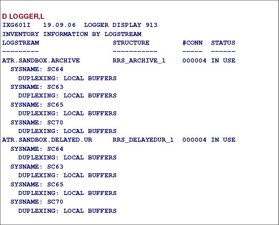
Figure 3-13 Displaying Logger information from RRS
Displaying System Logger information
To get information about the active RRS log streams and the status of these log streams, the command D LOGGER,L,LSN=ATR.* should be issued at the console.
When displaying log stream sysplex information, using D LOGGER,L, the options are as follows:
LSName or LSN = logstreamname This filter requests a display of all defined log streams that match the specified log stream name.
STRName or STRN = structurename This filter requests a display of all log streams on the sysplex that are defined to a structure that matches the specified structure name.
DASDONLY This filter requests a display of all log streams that match other filters that have a DASDONLY configuration.
3.11 XCF information about RRS structures

Figure 3-14 Display XCF information about allocated XCF structures
Displaying information about RRS structures
The D XCF,STR command shows you a summary of all the structures that are currently defined in the sysplex.
The command requests information about the coupling facility structures in the policy. If specified without further qualification, summary information (message IXC359I) will be displayed about all coupling facility structures that are in the policy. Using the STRNAME keyword requests the system to display detail information.
Figure 3-15 shows detailed information about all allocated RRS structures. The D XCF,STR,STRNAME=RRS* command gives you information about the status, the time when the structure was allocated, and the connectors to this structure.

Figure 3-15 Display information about a specific RRS structure
3.12 ATRQSRV batch utility support

Figure 3-16 ATRQSRV batch utility support
ATRQSRV batch utility
Currently there are three ways to unregister RMs:
•RRS ISPF panels
•Applications via the updated ATRSRV interface
•JCL via the ATRQSRV batch utility
Figure 3-17 shows a sample job for obtaining RRS RM information.
|
//LUTZRRS JOB ,'KUEHNER',NOTIFY=&SYSUID,
// CLASS=A,MSGCLASS=X,MSGLEVEL=(1,1),TIME=1440
//LISTATR EXEC PGM=ATRQSRV
//SYSPRINT DD SYSOUT=*
//SYSIN DD *
RMINFO RMNAME(IGWTV070020071121456262931740000)
//
|
Figure 3-17 Sample JCL for ATRQSRV use
List all resource managers
The following JCL can be used to list all resource managers:
//LISTRM JOB
//STEP1 EXEC PGM=ATRQSRV
//SYSPRINT DD SYSOUT=*
//SYSIN DD *
RMINFO
List all active units of recovery (URs)
The following JCL can be used to list all active recovery units:
//LISTUR JOB
//STEP1 EXEC PGM=ATRQSRV
//SYSPRINT DD SYSOUT=*
//SYSIN DD *
URINFO
Invoke ATRQSRV from REXX
The following code shows an example of invoking ATRQSRV from REXX. The output of the sample ATRQSRV is done using the variable atrprint.
|
/* REXX ***/* function : issue RRS functions
address tso "alloc f(SYSIN) new" /* allocate temporarly */
/* dataset for SYSIN */
address tso "alloc f(SYSPRINT) new" /* allocate temporarly */
/* dataset for SYSPRINT */
queue 'SYSINFO' /* pass function to ATRQSRV */
/* */
address tso 'execio 1 diskw SYSIN (finis' /* write SYSIN control */
/* statement to temporarly */
/* SYSIN file */
address tso 'ATRQSRV' /* invoke ATRQSRV service */
/* */
address tso 'execio * diskr SYSPRINT (stem atrprint.'
/* read the program output */
do i=1 to atrprint.0 /* print or manage the */
say atrprint.i /* output */
end /* */
/* */
address tso "free f(SYSPRINT)" /* deallocate SYSPRINT */
address tso "free f(SYSIN)" /* deallocate SYSIN */
exit /* good buy */
|
Figure 3-18 Invoking ATRQSRV from REXX
Resource manager unregister
Resource manager unregister processing can be requested by one of the following means:
•Exit back-end processing as a result of RRS detecting an RM exit failed exit failure
•Registration services unregister exit (ATRBMUNR)
In either case, RRS performs the RM unregister processing to mark all UR interests for the failing RM as failed and unset the RM’s RRS exits, as well as the RM unregistration processing with the registration services. If RRS experiences an internal failure before completing the RM unset processing, RM could be left in an unregistered state with registration services but still set with RRS. This situation cannot currently be resolved without recycling RRS and its resource managers, which is undesirable.
Instead, use the SETRRS CANCEL function to recycle the RRS address space. From the RRS ISPF panels Option 2, Display Resource Manager information, use the UNREGISTER RM command to unregister the resource manager with RRS.
3.13 RRS archive logging and ATRQSRV utility

Figure 3-19 Archive logging commands and ATQQSRV utility request
Archive logging commands
It is possible to experience severe performance impact of running RRS with the archive log stream. It is possible to run without it by deleting the archive log before starting any RRS image in the logging group or when RRS is operational.
After successfully defining the logstream, you can activate the archive logstream using the SETRRS command. A successful activation message ATR175I is issued.
The following command, SETRRS ARCHIVELOGGING, can be used to disable or enable RRS archive logging on a system:
SETRRS ARCHIVELOGGING,[DISABLE | ENABLE]
Where:
DISABLE Indicates the system is to disable RRS archive logging for the subsequent transactions. RRS will stop writing the transaction completion records to the archive log and disconnect from the archive log stream.
ENABLE Indicates the system is to enable RRS archive logging for the subsequent transactions. RRS will connect to the archive log stream and start writing the transaction completion records to the archive log. The ENABLE request is done by asynchronous processing and might take as long as 15 seconds before the Archive Log Stream is connected and the enable message (ATR175I) is issued.
..................Content has been hidden....................
You can't read the all page of ebook, please click here login for view all page.