
6
Interfacing External LEDs
In the previous chapter, we learned how to work with a built-in programmable LED matrix display and a pair of programmable built-in push buttons. We are now comfortable with using them in our projects.
This chapter explores how to connect with external discrete LEDs and products based on them. We will create exciting projects involving LEDs. We will also use our knowledge of working with built-in buttons to add interactivity to our projects. After that, we will start creating electronic circuits and program them with MicroPython.
The following is the list of topics that we will explore in this chapter:
- Breadboards and solderless circuits
- LEDs and their programming
- Chaser effect
- RGB LED
- Seven-segment display
Let’s explore programming LEDs with MicroPython and a Micro:bit.
Technical requirements
Apart from the usual setup, the demonstrations in this chapter need the following components:
- An MB102 breadboard
- Jumper wires
- LEDs of different colors
- An LED bar graph
- A common cathode RGB LED
- A common anode RGB LED
- A common cathode seven-segment LED display
- A common anode seven-segment LED display
Breadboards and solderless circuits
We can create circuits with electrical and electronic components such as LEDs, wires, and buttons. We need to use the soldering method to connect them to make them work. However, there is another method we can use to avoid soldering altogether. This method is known as breadboarding or prototyping. We have to use a component known as a breadboard to avoid soldering other components. The following is an image of an MB102-type breadboard:

Figure 6.1 – MB102 breadboard (courtesy: https://commons.wikimedia.org/wiki/File:Final_render_pic_on_breadboard.png)
A Dual In-Line Package Integrated Circuit (DIP IC) is mounted on the breadboard. Let’s see how breadboards are useful. Have a look at the top view of the breadboard:

Figure 6.2 – The top view of an MB102 breadboard (courtesy: https://commons.wikimedia.org/wiki/File:Bread_board_1480358_59_60_HDR_Enhancer.jpg)
The lines in Figure 6.2 marked with red and blue are known as bus lines. All the points are connected with a single line. These bus lines are usually used to supply power to the breadboard. The breadboard has a central groove that divides it into two parts so that we can conveniently mount any electrical/electronic component with two rows of male headers (refer to Figure 6.1). Furthermore, the two separated sections of the breadboard are grouped into collections of five points arranged vertically (refer to the green outline in Figure 6.2). All five points in a single collection are connected. This makes it easier for us to make multiple connections using a single pin of an electrical component. To connect the points to each other, as well as to various components, we can use jumper wires:
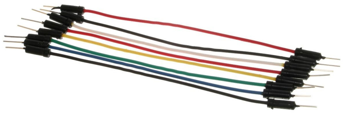
Figure 6.3 – Male-to-male header jumper wires (courtesy: https://commons.wikimedia.org/wiki/File:A_few_Jumper_Wires.jpg)
The jumper wires shown in Figure 6.3 are male-to-male jumper wires. They are also available in male-to-female and female-to-female header types. We can also directly work with the edge connector of the Micro:bit using crocodile clips:

Figure 6.4 – Crocodile clips (courtesy: https://commons.wikimedia.org/wiki/File:Jumper_Wires_with_Crocodile_Clips.jpg)
These are the essential components for building solderless circuits. We will be using these components frequently to build circuits. This will help demonstrate the concepts we will learn about throughout this book. In the next section, we will explore circuit-making with LEDs.
LEDs and their programming
In the previous chapter, we learned about the definition of LEDs and worked with the built-in programmable 5 x 5 LED matrix. Let’s see what a discrete LED looks like. Have a look at the following figure:
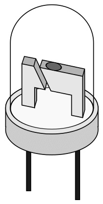
Figure 6.5 – An LED (courtesy: https://freesvg.org/1534357308)
An LED has got two connections – an anode (the longer leg in Figure 6.5) and a cathode (the shorter leg). An LED will glow when we connect the anode of the LED to positive voltage and the cathode to the ground. We know that the Micro:bit has a 3 V pin and a ground pin on its edge connector. We can use these pins with an LED for demonstration purposes, as follows:

Figure 6.6 – An LED connected to a Micro:bit
As we can see, it is difficult to understand the connections using photographs as we cannot see the wiring properly. That is why, for the circuit diagrams in the remainder of this book, we will use fritzing:
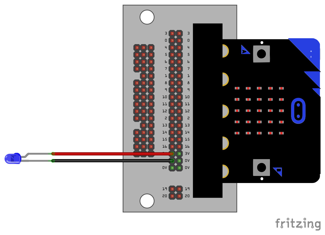
Figure 6.7 – A fritzing circuit
Note
We can also use Tinkercad (https://www.tinkercad.com) to create circuits. Tinkercad also simulates the circuit. It is a free online tool. As an exercise, explore Tinkercad.
As shown in Figure 6.7, connect the 3V pin of the Micro:bit to the anode of the LED and the GND to the cathode. The current will pass through the LED, and it will glow. We do not have to use any resistor in the circuit as we can also see the circuit schematics in fritzing:

Figure 6.8 – A fritzing schematic for an LED connected to a Micro:bit
If we connect the cathode to the 3V pin and the anode to the GND pin, then the LED will not glow. Try this now!
Let’s connect the anode of the LED to the digital General-Purpose Input/Output (GPIO) pin – that is, pin 0 – as shown in the following circuit diagram:

Figure 6.9 – An LED connected to pin 0 of a Micro:bit
The following is a schematic for this:
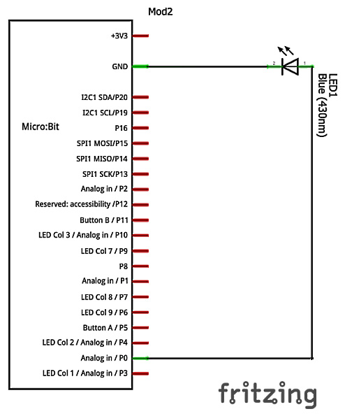
Figure 6.10 – Schematic of an LED connected to pin 0 of a Micro:bit
The LED will now glow automatically. We will have to write the following code to make it glow:
from microbit import *
pin0.write_digital(1)
We have to use the write_digital() method to send 3V or 0V to pin 0 (where 1 or 0 is used as an argument, respectively) of the Micro:bit.
Blinking an LED
We can even make the LED blink with the following code:
from microbit import *
try:
    while True:
        pin0.write_digital(1)
        sleep(500)
        pin0.write_digital(0)
        sleep(500)
except KeyboardInterrupt as e:
    print("Interrupted by the user...")
We are sending 3V and 0V to pin 0 of the Micro:bit for half a second in an alternate sequence.
SOS message
We know that three dots followed by three dashes, then followed by three dots (… --- …), represents an SOS message in the standard Morse code. We can create a visual SOS message with the same circuit by uploading the following code to the Micro:bit:
from microbit import *
try:
    while True:
        pin0.write_digital(1)
        sleep(500)
        pin0.write_digital(0)
        sleep(500)
        pin0.write_digital(1)
        sleep(500)
        pin0.write_digital(0)
        sleep(500)
        pin0.write_digital(1)
        sleep(500)
        pin0.write_digital(0)
        sleep(1500)
        pin0.write_digital(1)
        sleep(1500)
        pin0.write_digital(0)
        sleep(500)
        pin0.write_digital(1)
        sleep(1500)
        pin0.write_digital(0)
        sleep(500)
        pin0.write_digital(1)
        sleep(1500)
        pin0.write_digital(0)
        sleep(1500)
        pin0.write_digital(1)
        sleep(500)
        pin0.write_digital(0)
        sleep(500)
        pin0.write_digital(1)
        sleep(500)
        pin0.write_digital(0)
        sleep(500)
        pin0.write_digital(1)
        sleep(500)
        pin0.write_digital(0)
        sleep(1500)
except KeyboardInterrupt as e:
    print("Interrupted by the user...")
We have now created the virtual SOS message.
Blinking two LEDs alternately
We can use pin 1 to connect another LED, as follows:

Figure 6.11 – Two LEDs connected to a Micro:bit
The following is the schematic of the circuit:

Figure 6.12 – Schematic for two LEDs connected to a Micro:bit
We can write a program to make the LEDs blink alternately, as follows:
from microbit import *
try:
    while True:
        pin0.write_digital(1)
        pin1.write_digital(0)
        sleep(500)
        pin1.write_digital(1)
        pin0.write_digital(0)
        sleep(500)
except KeyboardInterrupt as e:
    print("Interrupted by the user...")
If we run the code, we will see that the LEDs are blinking alternately. We can also write the following code to produce the same output as the preceding code but using the if condition:
from microbit import *
counter = 0
try:
    while True:
        if counter % 2 == 0:
            led1 = pin0
            led2 = pin1
        else:
            led1 = pin1
            led2 = pin0
        led1.write_digital(1)
        led2.write_digital(0)
        sleep(500)
        counter = counter + 1
except KeyboardInterrupt as e:
    print("Interrupted by the user...")
Again, this will make both LEDs blink alternately.
Traffic light simulator
We can also simulate traffic lights. For this, we will need three LEDs that are green, yellow (or orange), and red. Create a circuit, as shown in the following figure:

Figure 6.13 – Circuit diagram for a traffic light
The following is the schematic for the traffic light simulator:

Figure 6.14 – Schematic for the traffic light simulator
The program is simple. I have created three user-defined functions that I am calling in an infinite loop, as follows:
from microbit import *
green = pin0
yellow = pin1
red = pin2
delay_green = delay_red = 5000
delay_yellow = 2000
def green_light():
    green.write_digital(1)
    yellow.write_digital(0)
    red.write_digital(0)
def yellow_light():
    green.write_digital(0)
    yellow.write_digital(1)
    red.write_digital(0)
def red_light():
    green.write_digital(0)
    yellow.write_digital(0)
    red.write_digital(1)
try:
    while True:
          green_light()
          sleep(delay_green)
          yellow_light()
          sleep(delay_yellow)
          red_light()
          sleep(delay_red)
except KeyboardInterrupt as e:
    print("Interrupted by the user...")
We have simulated traffic lights using the Micro:bit.
GPIO pins usage
Not all the GPIO pins can be programmed with MicroPython as a few of them are reserved. Let’s demonstrate this. Run the following program:
from microbit import *
display.on()
try:
    while True:
        pin3.write_digital(1)
        sleep(500)
        pin3.write_digital(0)
        sleep(500)
except KeyboardInterrupt as e:
    print("Interrupted by the user...")
It will return the following error:
>>> %Run -c $EDITOR_CONTENT
Traceback (most recent call last):
  File "<stdin>", line 7, in <module>
ValueError: Pin 3 in display mode
This is because pin 3 is used by the built-in display matrix. This message about display mode is shown when we use pins 3, 4, 6, 7, and 10. This happens because these pins are connected to the built-in LED matrix of the Micro:bit. We will learn how to enable them at the end of the next section.
Pins 5 and 11 are used by two built-in push buttons labeled A and B. Trying to use these pins will show us the following error messages:
>>> %Run -c $EDITOR_CONTENT
Traceback (most recent call last):
  File "<stdin>", line 8, in <module>
ValueError: Pin 5 in button mode
>>> %Run -c $EDITOR_CONTENT
Traceback (most recent call last):
  File "<stdin>", line 9, in <module>
ValueError: Pin 11 in button mode
We cannot use these two pins (5 and 11) with LEDs using MicroPython.
Pins 17 and 18 are undefined as trying to use them in the program will result in the following errors:
>>> %Run -c $EDITOR_CONTENT
Traceback (most recent call last):
  File "<stdin>", line 9, in <module>
NameError: name 'pin17' isn't defined
>>> %Run -c $EDITOR_CONTENT
Traceback (most recent call last):
  File "<stdin>", line 9, in <module>
NameError: name 'pin18' isn't defined
Pins 19 and 20 are used for Inter-Integrated Circuit (I2C) buses and trying to use them in our program will result in the following errors:
>>> %Run -c $EDITOR_CONTENT
Traceback (most recent call last):
  File "<stdin>", line 8, in <module>
ValueError: Pin 19 in i2c mode
>>> %Run -c $EDITOR_CONTENT
Traceback (most recent call last):
  File "<stdin>", line 8, in <module>
ValueError: Pin 20 in i2c mode
Normally, we can use pins 0, 1, 2, 8, 9, 12, 13, 14, 15, and 16 directly for GPIO. We can also enable other pins, as we will see at the end of the next section.
4-bit binary counter
We can create a 4-bit binary counter with four LEDs (or a bigger counter with more LEDs). Create the circuit shown in the following diagram:

Figure 6.15 – Circuit for a 4-bit binary counter
Let’s see the schematic for a 4-bit binary counter:

Figure 6.16 – Schematic for a 4-bit binary counter
Now, let’s write the code for it:
from microbit import *
counter_led_pins = [pin0, pin1, pin2, pin8]
counter = 0
try:
    while True:
        for i in range(4):
            signal = int('{:04b}'.format(counter)[i])
            print(signal)
            counter_led_pins[i].write_digital(signal)
        print('------')
        if counter == 15:
            counter = 0
        else:
            counter = counter + 1
        sleep(1000)
except KeyboardInterrupt as e:
    print("Interrupted by the user...")
In this example, we created a list of the four pins. Then, we created a counter that cycles from 0 to 15. In each iteration of the loop, we compute the binary representation of the counter (using the format() method, where {:04b} means a 4-bit binary number representation) and assign every bit of that binary number to the group of pins. Thus, they will glow momentarily to represent the binary number. Pin 0 represents the most significant bit, while pin 8 represents the least significant bit of the binary representation of the counter. This is how we can write simple programs to demonstrate the working of LEDs.
Chaser effect
We can prepare a program for the chaser effect. The chaser effect is created by multiple LEDs blinking one after another in rapid succession. Connect LEDs to pins 0, 1, 2, 8, 9, 12, 13, 14, 15, and 16. I won’t give you the circuit diagram this time as I believe that by now, you can comfortably understand how to prepare a simple circuit by following the description. We can blink the LEDs together with the following program:
from microbit import *
pins = [pin0, pin1, pin2,
        pin8, pin9, pin12,
        pin13, pin14, pin15,
        pin16]
try:
    while True:
        for pin in pins:
            pin.write_digital(1)
        sleep(1000)
        for pin in pins:
            pin.write_digital(0)
        sleep(1000)
except KeyboardInterrupt as e:
    print("Interrupted by the user...")
This program tests whether all the connections are correct. We can make simple modifications to it to create a simple chaser effect, as follows:
try:
    while True:
        for pin in pins:
            pin.write_digital(1)
            sleep(100)
        for pin in pins:
            pin.write_digital(0)
            sleep(100)
except KeyboardInterrupt as e:
    print("Interrupted by the user...")
Here, we have changed the positions of the call to the sleep() method, and we have also changed the arguments that are passed. The arguments that are passed to sleep() decide the speed of the effect.
We can also make all the LEDs blink one after another in rapid succession, as follows:
from microbit import *
pins = [pin0, pin1, pin2,
        pin8, pin9, pin12,
        pin13, pin14, pin15,
        pin16]
def blink(pin, duration):
    pin.write_digital(1)
    sleep(duration)
    pin.write_digital(0)
    sleep(duration)
try:
    while True:
        for pin in pins:
            blink(pin, 100)
except KeyboardInterrupt as e:
    print("Interrupted by the user...")
In this example, we created a custom function, blink(), and called it in a loop. We can make this effect bidirectional by modifying the loop in the following way:
try:
    while True:
        for pin in pins:
            blink(pin, 100)
        for pin in reversed(pins):
            blink(pin, 100)
except KeyboardInterrupt as e:
    print("Interrupted by the user...")
We can create a fancy effect by making the following modification to the loop:
try:
    while True:
        for i in range(0, len(pins), 1):
            blink(pins[i], 100)
            if not (i-1)<0:
                blink(pins[i-1], 100)
        for i in range(len(pins)-1, -1, -1):
            blink(pins[i], 100)
            if not (i+1)>8:
                blink(pins[i+1], 100)
except KeyboardInterrupt as e:
    print("Interrupted by the user...")
As we can see, the possibilities when writing code for this circuit are unlimited. I have used LEDs of a single color. However, you may wish to use LEDs of different colors to spice up the effect. You can also arrange them in a different geometric pattern.
Using an LED bar graph
Many manufacturers produce LEDs embedded in to a single package, known as LED bar graph, as shown in the following figure:

Figure 6.17 – An LED Bar Graph (courtesy: https://commons.wikimedia.org/wiki/File:MFrey_LN3914N_AD-Converter.jpg)
In Figure 6.17, on the right-hand side, we can see an LED Bar Graph in action in an electronics project. It usually comes with 10 LEDs packaged in it. The LED Bar Graph has two rows of headers (like an integrated circuit) and fits perfectly around a breadboard’s central groove. One row of the header is for applying the positive voltage, which should all be connected to GPIO pins. Another row must be connected to the ground. We have already created a circuit with 10 LEDs for the chaser effect. We can replace all 10 LEDs with a 10 LED Bar Graph. As an exercise, I built that circuit by replacing LEDs with the LED Bar Graph and ran all the earlier chaser programs with the new circuit to see the LED Bar Graph in action.
Enabling more pins
Earlier, we saw that pins 3, 4, 6, 7, and 10 could not be used directly in our programs for digital output as they are used by the built-in LED matrix. We can use them by disabling the matrix using the display.off() statement. So, before using these pins in our program, we just need to use that statement, and the pins can be used. The downside, however, is that we won’t be able to use the built-in display in parallel. To turn the display on, we have to call display.on(). You may have noticed that we called this while using the display in Chapter 5, Programming Built-In LEDs and Buttons. It’s always a good practice to explicitly call this before using the display, as the previous program may have turned it off.
In this section, we created the chaser effect with external LEDs and also learned how to enable the pins connected to the display by turning the display off.
RGB LEDs
RGB LEDs can emit three colors: red, green, and blue. They have four pins, one for each color; the remaining pin acts as a common cathode or common anode. The following circuit diagram shows the common cathode LED connection to the Micro:bit:
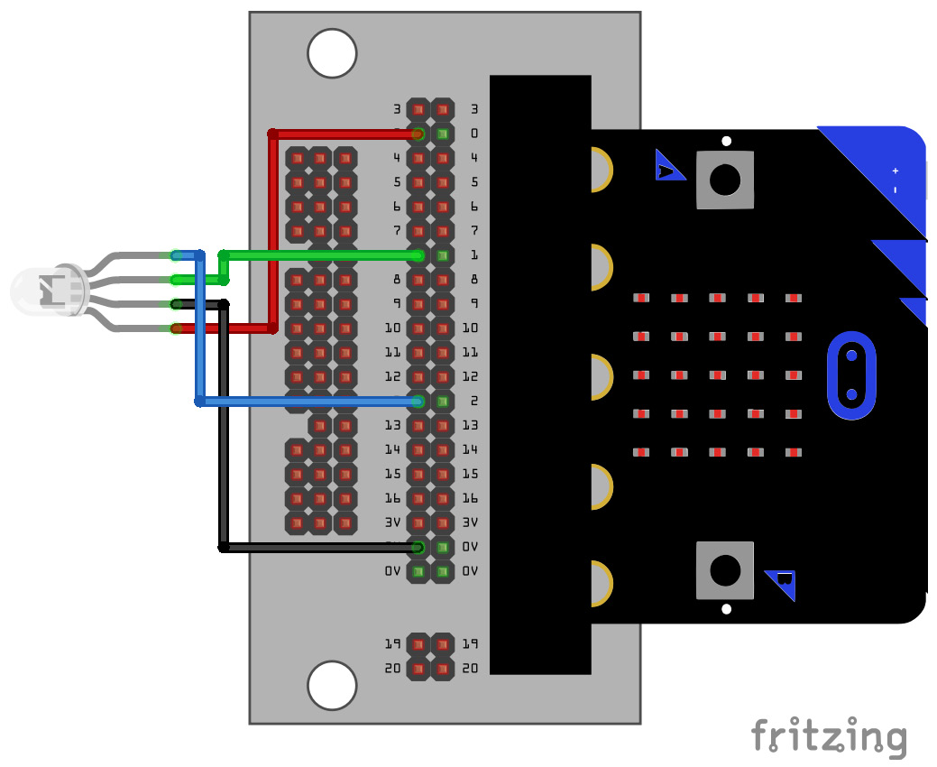
Figure 6.18 – An RGB LED (common cathode)
In a common cathode LED, we must apply a positive voltage to the color pins to activate the corresponding LEDs. We have connected the common cathode to the ground, the red pin to pin 0, the green pin to pin 1, and the blue pin to pin 2. The program that cycles through all the colors that this combination of digital outputs can produce is quite simple and intuitive, as follows:
from microbit import *
red = pin0
green = pin1
blue = pin2
def glow(red_val, green_val, blue_val):
    red.write_digital(red_val)
    green.write_digital(green_val)
    blue.write_digital(blue_val)
try:
    while True:
        glow(0, 0, 0)
        sleep(1000)
        glow(0, 0, 1)
        sleep(1000)
        glow(0, 1, 0)
        sleep(1000)
        glow(0, 1, 1)
        sleep(1000)
        glow(1, 0, 0)
        sleep(1000)
        glow(1, 0, 1)
        sleep(1000)
        glow(1, 1, 0)
        sleep(1000)
        glow(1, 1, 1)
        sleep(1000)
except KeyboardInterrupt as e:
    print("Interrupted by the user...")
We can even modify the 4-bit counter program and turn it into a 3-bit counter (again, we are using format() and {:03b} to represent a 3-bit binary number). It will also cycle through all the possible combinations of colors. This is the program:
from microbit import *
rgb = [pin0, pin1, pin2]
counter = 7
try:
    while True:
        for i in range(len(rgb)):
            signal = int('{:03b}'.format(counter)[i])
            print(signal)
            rgb[i].write_digital(signal)
        print('------')
        if counter == 7:
            counter = 0
        else:
            counter = counter + 1
        sleep(1000)
except KeyboardInterrupt as e:
    print("Interrupted by the user...")
In a common anode RGB LED circuit, we need to connect the common anode pin to the 3V pin of the Micro:bit, as shown in the following circuit diagram:
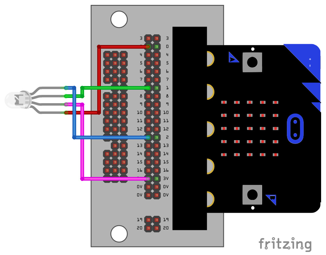
Figure 6.19 – An RGB LED (common anode)
The programs will remain the same. The preceding two programs will work perfectly for a common anode RGB LED. Only the order in which the colors are displayed will be reversed because, with common anode LEDs, we need to apply 0V to the color pins to activate the LEDs.
RGB LEDs are commonly used in maker projects. Knowing how to use them is advantageous. In this section, we learned about them in detail.
Seven-segment display
We can also work with special display devices that come with eight LEDs in them. They are known as seven-segment LEDs. They can display decimal numbers and decimal points. The following is a diagram of a common cathode seven-segment LED display:
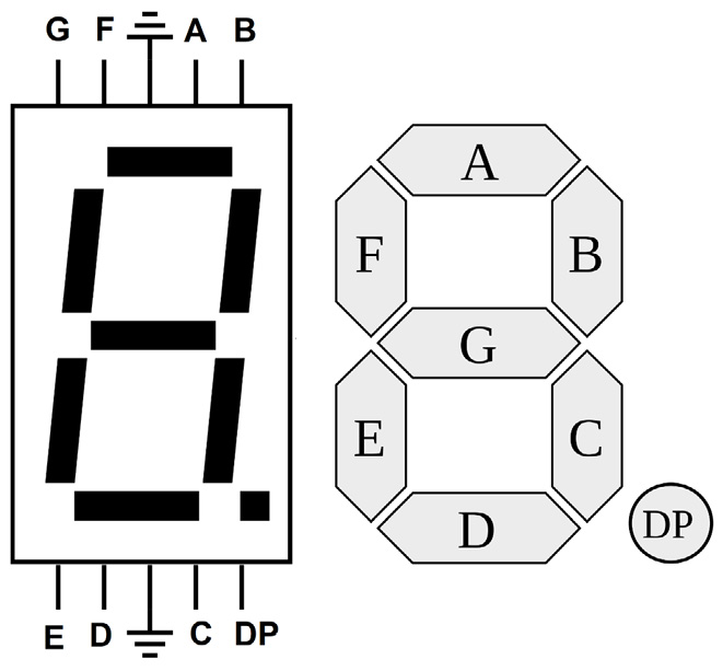
Figure 6.20 – A common cathode seven-segment LED display (courtesy: https://commons.wikimedia.org/wiki/File:7-Segment_Display_Visual_Pinout_Diagram.svg and https://commons.wikimedia.org/wiki/File:7_segment_display_labeled.svg)
We must apply a positive voltage to the corresponding pins and connect the common cathode pins to the ground. We can show numbers and a few alphabetical characters with a combination of pins. For example, if we activate pins A, B, C, D, E, and F together, it will show 0. Similarly, you can figure out what pins are to be activated for other numbers and characters. As an exercise for this chapter, connect this display to the Micro:bit and write a program that cycles through all the decimal and hexadecimal numbers in a continuous loop.
These displays are available in the common anode configuration too. The common anode pins must be connected to the 3V pin of the Micro:bit; to activate the LED, we have to send a LOW (that is, 0) signal to the corresponding LED. As an exercise, create a circuit for the common anode seven-segment LED display with the Micro:bit. You will need to make major modifications to the program you would write for a common cathode LED.
Summary
In this chapter, we started building circuits with external LEDs and derived electronic components. We have learned how to create interesting projects with our acquired knowledge.
In the next chapter, we will explore how to connect push buttons, slide switches, buzzers, and stepper motors to the Micro:bit and program them with MicroPython.
Further reading
You can find more information about GPIO pins and the Micro:bit-specific MicroPython API at https://microbit-micropython.readthedocs.io/en/v1.0.1/pin.html.