
1
Introduction to the BBC Micro:bit
I certainly hope that you have read the preface and the table of contents, which provide a fair idea about our journey into the amazing world of the BBC Micro:bit (also written as Micro:bit or Micro Bit). This introductory chapter will warm you up for the upcoming exciting journey into the vast world of the Micro:bit. The road ahead is full of interesting concepts and projects. It is always a good idea to prepare well for the journey ahead, and this chapter will accomplish that.
We will explore the following topics in this chapter:
- The history of the Micro:bit
- The specifications of Micro:bit V1 and Micro:bit V2
- Powering up the Micro:bit
- Breakout boards
- Fritzing to create circuit diagrams
Let’s get started!
Technical requirements
We will need the following hardware for this chapter:
- BBC Micro:bit V1 or V2
- A computer with Windows, macOS, or Linux
- A BBC Micro:bit edge connector
- A Micro-USB to USB cable
- An internet connection
- A mobile power bank
- Kitronik Mi:power
The history of the Micro:bit
It is important to know the history of the BBC Micro:bit. The British Broadcasting Corporation (BBC) is the United Kingdom’s public broadcaster. It is also the world’s oldest and biggest broadcaster. BBC has always been pioneering in creating programs for outreach in science and technology to improve the public understanding of science. Its programs include various documentaries and television series.
One such interesting television series was The Computer Programme. It was broadcast on BBC Two and used a home computer, the BBC Micro, conceptualized by the BBC and developed by Acorn Computers. The TV series was a part of the BBC Computer Literacy Project. The BBC Micro had six different models, which were all based on the famous MOS Technology 6502 8-bit microprocessor. It is a simplified and faster version of the Motorola 6800 microprocessor. The 6502 is a very popular microprocessor, and variants of it were used in popular video game consoles and computers such as Atari 2600, Apple II, Nintendo Entertainment System (popularly known as NES or Famicom), Commodore 64, and, of course, the BBC Micro. The BBC Micro was very successful, and it made a great impact in the computer education sector, leaving a great legacy behind.
In 2012, with the release of Raspberry Pi, a new era was ushered into the world of computing and education. Through the Computer Literacy Project, the BBC sought to build upon the legacy of the BBC Micro after the great success of Raspberry Pi. It onboarded many partners from industry, such as Microsoft, and academia, such as Lancaster University. The first version (now referred to as the Micro:bit V1) was launched in July 2015 and was available for general sale in March 2016. The BBC also gave hundreds of thousands of Micro:bits to school children in the UK as a part of science education outreach. After the Micro:bit successfully launched, the BBC formed a not-for-profit organization known as the Microbit Foundation.
Note
For more details, you can visit the home page of the Microbit Foundation at https://microbit.org/.
In October 2020, the Microbit Foundation released the second version of the Micro:bit. V2 has got better specifications than V1 at the same price. We will explore the specifications of V1 and V2 side by side in the following section.
The specifications of Micro:bit V1 and Micro:bit V2
The following table compares the features of the BBC Micro:bit V1 and V2 side by side (source: https://microbit.org/):
|
BBC Micro:bit |
V1 |
V2 |
|
Processor |
Nordic nRF51822 |
Nordic nRF52833 |
|
Flash memory |
256 KB |
512 KB |
|
RAM |
16 KB |
128 KB |
|
Speed |
16 MHz |
64 MHz |
|
Bluetooth |
Bluetooth 4.0 |
Bluetooth 5.1 with Bluetooth Low Energy (BLE) |
|
Radio communication |
2.4 GHz radio (80 channels) |
2.4 GHz radio (80 channels) |
|
Buttons |
Two programmable (A and B) and one system (reset) |
Two programmable (A and B) and one system (power/reset) |
|
On/off switch |
None |
Press and hold the rear power button |
|
Touchpad |
None |
Touch-sensitive logo |
|
Microphone |
None |
Onboard Knowles SPU0410LR5H-QB-7 MEMS microphone (with LED indicator) |
|
Display |
5x5 programmable LED matrix (25 LEDs in total) |
5x5 programmable LED matrix (25 LEDs in total) |
|
Speaker |
None |
Onboard JIANGSU HUANENG MLT-8530 (up to 80 dB) |
|
Motion sensor and compass |
LSM303AGR |
LSM303AGR |
|
Temperature sensor |
On-board temperature sensor |
On-core NRF52 |
|
Edge connector |
25 pins |
25 pins |
Table 1.1 – Comparison of the features of BBC Micro:bit V1 and V2
The processors used in both versions are a special type of processor known as a System on Chip (also abbreviated as SoC or SOC). An SoC is an Integrated Circuit (IC) that has all or most components of a complete working computer system. A typical SoC has a processor, flash memory, and RAM. Both versions employ Advanced RISC Machines (ARM) processors. The ARM uses Reduced Instruction Set Computer (RISC) instruction architecture. The V1 uses Nordic nRF51822 SoC (https://www.nordicsemi.com/Products/nRF51822), and the V2 uses Nordic nRF52833 (https://www.nordicsemi.com/products/nrf52833). The Random Access Memory (RAM) is used to execute the programs. The flash memory is used to store the programs, and it is reprogrammable.
The following diagram shows the front faces of V2 and V1 side by side:

Figure 1.1 – Hardware features on the fronts of V2 and V1 (courtesy: ©Micro:bit Educational Foundation/microbit.org)
The following diagram shows the rear of the V2 and V1 side by side:
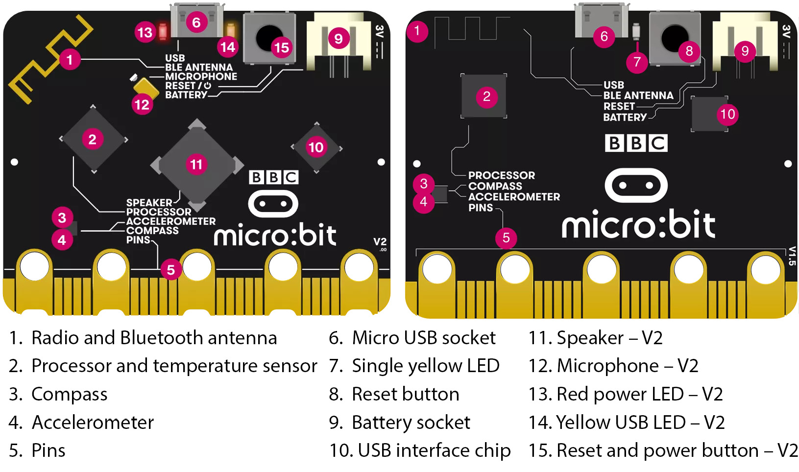
Figure 1.2 – The hardware features on the rears of V2 and V1 (courtesy: ©Micro:bit Educational Foundation/microbit.org)
Another important aspect of the Micro:bit boards of both versions is that they come with edge connectors to interface with external hardware components. The following diagram explains the slight difference between the edge connectors of V2 and V1 side by side:

Figure 1.3 – The edge connectors of V2 and V1 (courtesy: https://tech.microbit.org/hardware/edgeconnector/)
You can read online about the edge connectors in detail at https://tech.microbit.org/hardware/edgeconnector/ and https://microbit.pinout.xyz/.
I understand that you may feel a bit overwhelmed with all this technical information at this stage. Without enough context about the utility of this technical information, it is natural to feel that way. However, in the upcoming chapters, we will learn about and demonstrate all these features in detail.
Now that we have a fair understanding of the history and specifications of the Micro:bit, let’s learn various methods to power it up.
Powering up the Micro:bit
There are a few ways we can power up the Micro:bit. Let’s see them all one by one. The following diagram clearly shows the micro-USB port and the battery socket. We can power up the BBC Micro:bit using these:
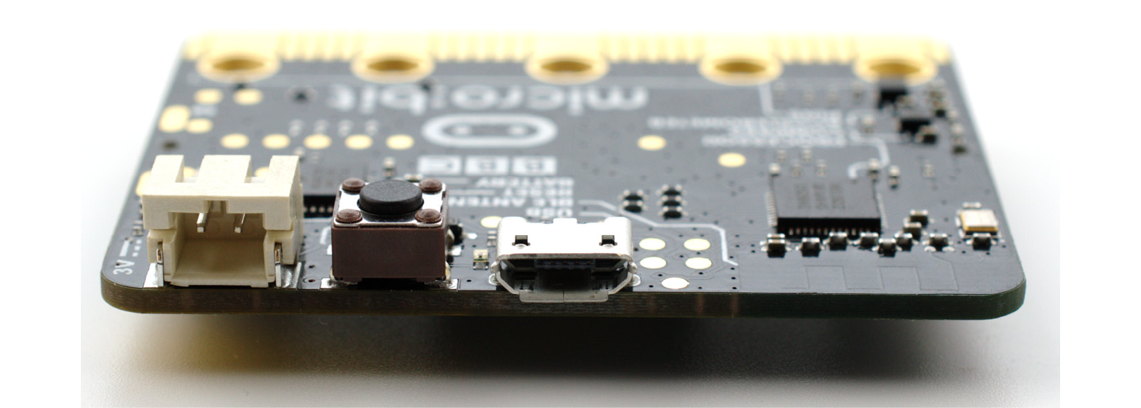
Figure 1.4 – The battery socket and micro-USB port (courtesy: https://commons.wikimedia.org/wiki/File:BBC_micro_bit_%2826238853955%29.png)
We can use a micro-USB male to USB male cable to power the Micro:bit. The following is the micro-USB end of such a cable:

Figure 1.5 – A micro-USB male connector (courtesy: https://commons.wikimedia.org/wiki/File:MicroB_USB_Plug.jpg)
Insert this end into the Micro:bit, as shown in the following photo:
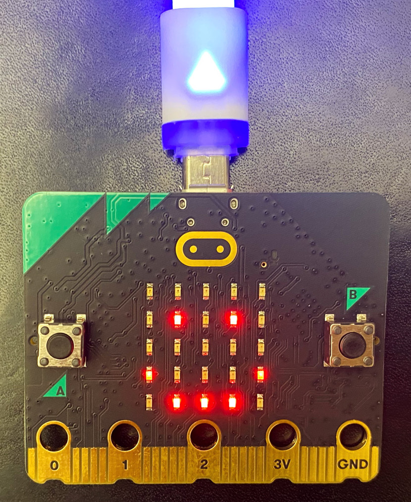
Figure 1.6 – A micro-USB male connector (courtesy: https://commons.wikimedia.org/wiki/File:Bbc-microbit-2021.jpg)
Insert the other end into a computer or a power bank. The following is an image of a mobile/portable power bank:
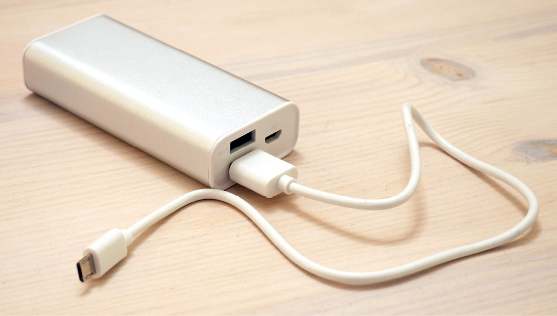
Figure 1.7 – A power bank with a micro USB cable attached (courtesy: https://commons.wikimedia.org/wiki/File:Portable_power_bank.jpg)
We can also use a pair of AAA batteries with a special connector, as shown in the following photo:
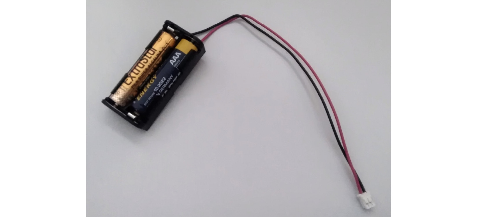
Figure 1.8 – A battery connector (courtesy: https://commons.wikimedia.org/wiki/File:Cavo_Microbit.jpg)
You can procure such a connector online at various marketplaces. One such page is https://www.sparkfun.com/products/15101. There are many other websites too that sell these connectors. You can also check your local makers’ electronic supply shops for this.
The following photo shows the Micro:bit powered up with this connector and a pair of AAA batteries:

Figure 1.9 – A battery connector connected to the Micro:bit
We can also power the Micro:bit with a CR2032-type power cell, as shown in the following figure:

Figure 1.10 – CR2032 power cells (courtesy: https://commons.wikimedia.org/wiki/File:Cr2032-7mmgrid.jpg)
We can use various special connectors to connect it with the Micro:bit. One special connector board is MI – the power board by Kitronik (https://kitronik.co.uk/products/5610-mipower-board-for-the-bbc-microbit). Figure 1.11 shows a photo of the board, the nuts, and the CR2032 battery that comes with it:
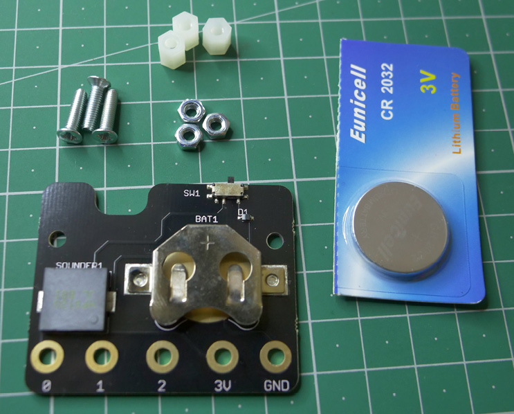
Figure 1.11 – The MI:power board and contents of the package
Figure 1.12 is a photo of the rear of the Micro:bit attached to the MI:power board:
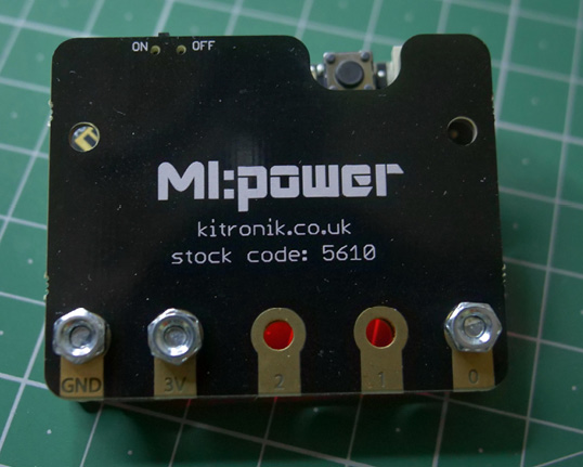
Figure 1.12 – The Micro:bit assembled with the MI:power board
We can see that there is a dedicated ON/OFF switch. Attaching the board to the Micro:bit is very easy, and we can check the instructions for assembly at https://kitronik.co.uk/products/5610-mipower-board-for-the-bbc-microbit.
Both versions of the Micro:bit come with booklets, as shown in the following image:
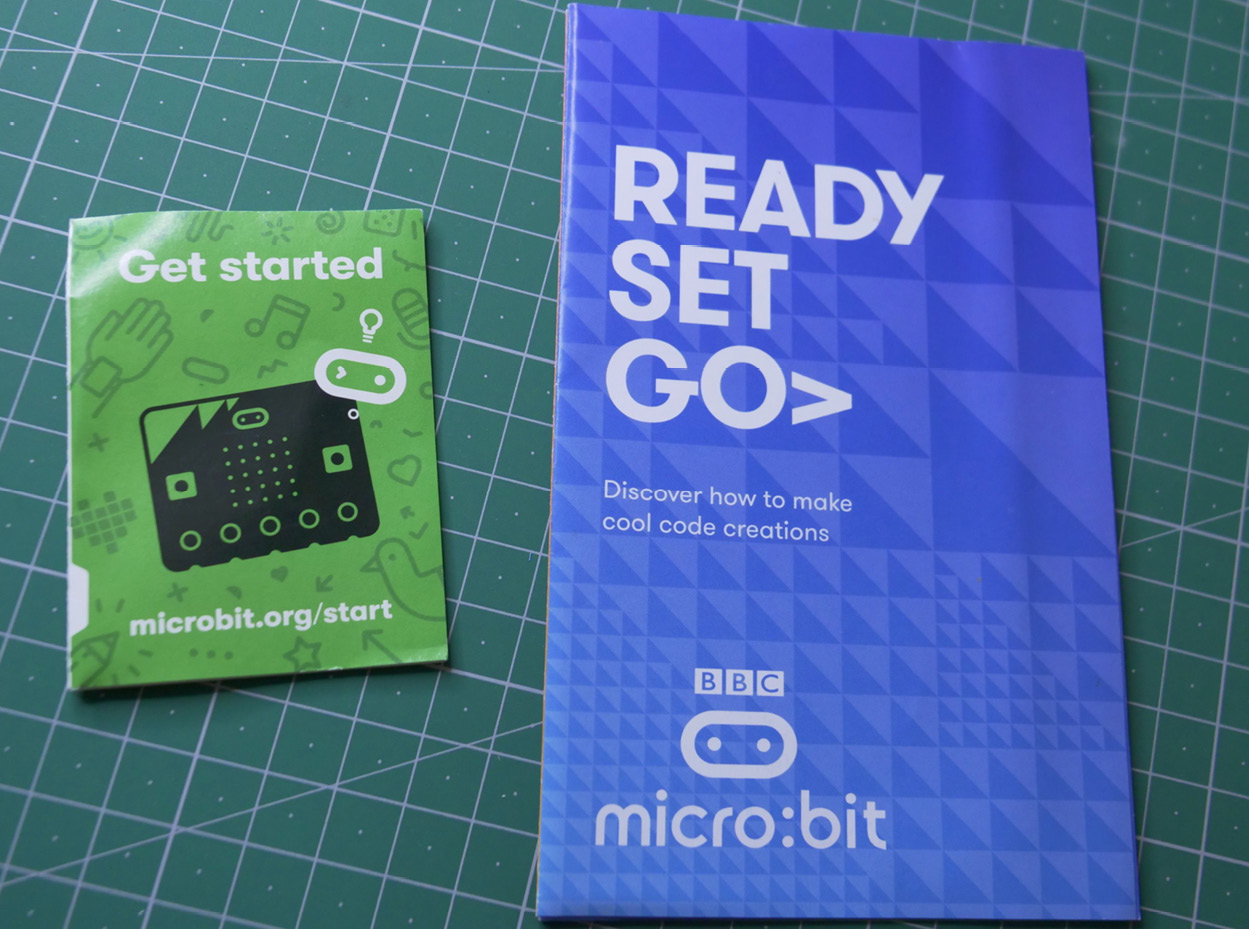
Figure 1.13 – Micro:bit instruction booklets
It is recommended to go through them for a better understanding.
The out-of-box experience
When we unbox the Micro:bit and power it up for the very first time, it runs a factory default program known as the out-of-box experience. It is lots of fun to learn about the features of the Micro:bit using this program. Unbox and power your Micro:bit to run this program. Enjoy exploring the features of the Micro:bit.
Now that we have explored various ways to power the Micro:bit, we will explore special hardware components known as breakout boards.
Breakout boards
The General Purpose Input Output (GPIO) pins of the Micro:bit are extremely narrowly printed on the edge connector. It is difficult to use them directly, and soldering can ruin the board. So, many organizations have developed special products that make the GPIO pins of the Micro:bit easily accessible. These products are known by various names, such as breakout boards, GPIO expanders, I/O extensions, and edge connectors. The following are the URLs of the web pages for such products:
- https://www.sparkfun.com/products/16445
- https://kitronik.co.uk/collections/microbit-and-accessories/products/5601b-edge-connector-breakout-board-for-bbc-microbit-pre-built
- https://robu.in/product/microbit-gpio-expansion-board/
- https://www.dfrobot.com/product-1867.html
- https://wiki.dfrobot.com/IO_Extender_for_microbit_V2.0_SKU_MBT0008
I urge you all to procure one of these or any other edge connector of your choice, as we will need these for the demonstrations in this book.
I, too, own a couple of them, as shown in the following photos:
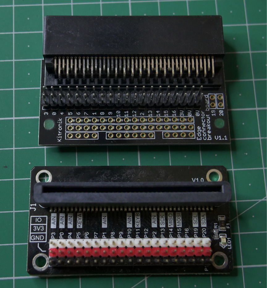
Figure 1.14 – A couple of edge connectors I own
Here, we have Micro:bit V1 and V2 inserted into the edge connectors:

Figure 1.15 – Micro:bits with the edge connectors
In the following section, we will get acquainted with a software program, Fritzing, that will help us visualize circuits.
Fritzing to create circuit diagrams
I am using software known as Fritzing (https://fritzing.org/) to create the circuits depicted in this book. It is not mandatory software for the demonstrations, as all the circuit diagrams are already printed in the book. However, if you wish to create your own circuit diagrams with Fritzing, you must procure them separately for 8 euros from https://fritzing.org/download/. I have included the Fritzing diagram files (with the .fzz extension) in the code bundle of the book. You can open them using the Fritzing software and modify them. It is very convenient software, and many hardware hackers (including us, the book’s authors) use it to design and visualize their projects.
Fritzing has a library of many routinely used electronic and electrical components that include various boards. Also, users can create their own custom components such as boards and add them to their Fritzing setup. Many of them make such components available to other users for free. These components are stored in files with the .fzpz extension. You can find the component files for the BBC Micro:bit and many edge connectors at the following URLs:
- https://tech.microbit.org/docs/hardware/assets/Microbit.fzpz.zip
- https://forum.fritzing.org/t/improved-micro-bit-part/7288
Download the part files. Open the Fritzing software. In the Parts panel (the top-right panel), right-click on an empty gray space to show a dropdown, as shown in Figure 1.16:
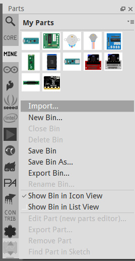
Figure 1.16 – Importing a part to Fritzing
The first option is Import…. Click on that, and it opens a standard file selection window of the OS. Select the downloaded component files for the Micro:bit and edge connectors (those with the .fzpz extension) and import them. We can import only one component at a time. Once imported, all the components will be visible in the tab labeled MINE (refer to Figure 1.16). The following figure is a screenshot of those components added to a circuit diagram under development:
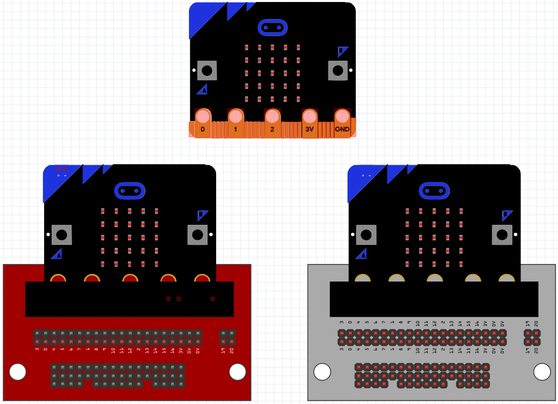
Figure 1.17 – Using the BBC micro:bit and edge connector parts in circuit diagrams
This is how Fritzing can be used to visualize the circuits we will build for the demonstrations throughout this book. You will find similar and more detailed circuit diagrams in the upcoming chapters of the book.
Summary
In this chapter, we learned a few fundamentals about the BBC Micro:bit. We had a brief tour of the hardware features that we will explore in the coming chapters. We also learned about the ways to power the board and edge connectors.
In the next chapter, we will focus on the software aspect of the Micro:bit and learn the basics of Python and MicroPython. We will start with installing various IDEs. We will also learn how to upgrade the firmware of the Micro:bit.
Further reading
For more information, visit the following links: