
Chapter 5. Big Data Storage Concepts

File Systems and Distributed File Systems
Data acquired from external sources is often not in a format or structure that can be directly processed. To overcome these incompatibilities and prepare data for storage and processing, data wrangling is necessary. Data wrangling includes steps to filter, cleanse and otherwise prepare the data for downstream analysis. From a storage perspective, a copy of the data is first stored in its acquired format, and, after wrangling, the prepared data needs to be stored again. Typically, storage is required whenever the following occurs:
• external datasets are acquired, or internal data will be used in a Big Data environment
• data is manipulated to be made amenable for data analysis
• data is processed via an ETL activity, or output is generated as a result of an analytical operation
Due to the need to store Big Data datasets, often in multiple copies, innovative storage strategies and technologies have been created to achieve cost-effective and highly scalable storage solutions. In order to understand the underlying mechanisms behind Big Data storage technology, the following topics are introduced in this chapter:
• clusters
• file systems and distributed files systems
• NoSQL
• sharding
• replication
• CAP theorem
• ACID
• BASE
Clusters
In computing, a cluster is a tightly coupled collection of servers, or nodes. These servers usually have the same hardware specifications and are connected together via a network to work as a single unit, as shown in Figure 5.1. Each node in the cluster has its own dedicated resources, such as memory, a processor, and a hard drive. A cluster can execute a task by splitting it into small pieces and distributing their execution onto different computers that belong to the cluster.

File Systems and Distributed File Systems
A file system is the method of storing and organizing data on a storage device, such as flash drives, DVDs and hard drives. A file is an atomic unit of storage used by the file system to store data. A file system provides a logical view of the data stored on the storage device and presents it as a tree structure of directories and files as pictured in Figure 5.2. Operating systems employ file systems to store and retrieve data on behalf of applications. Each operating system provides support for one or more file systems, for example NTFS on Microsoft Windows and ext on Linux.

A distributed file system is a file system that can store large files spread across the nodes of a cluster, as illustrated in Figure 5.3. To the client, files appear to be local; however, this is only a logical view as physically the files are distributed throughout the cluster. This local view is presented via the distributed file system and it enables the files to be accessed from multiple locations. Examples include the Google File System (GFS) and Hadoop Distributed File System (HDFS).

NoSQL
A Not-only SQL (NoSQL) database is a non-relational database that is highly scalable, fault-tolerant and specifically designed to house semi-structured and unstructured data. A NoSQL database often provides an API-based query interface that can be called from within an application. NoSQL databases also support query languages other than Structured Query Language (SQL) because SQL was designed to query structured data stored within a relational database. As an example, a NoSQL database that is optimized to store XML files will often use XQuery as the query language. Likewise, a NoSQL database designed to store RDF data will use SPARQL to query the relationships it contains. That being said, there are some NoSQL databases that also provide an SQL-like query interface, as shown in Figure 5.4.

Sharding
Sharding is the process of horizontally partitioning a large dataset into a collection of smaller, more manageable datasets called shards. The shards are distributed across multiple nodes, where a node is a server or a machine (Figure 5.5). Each shard is stored on a separate node and each node is responsible for only the data stored on it. Each shard shares the same schema, and all shards collectively represent the complete dataset.

Figure 5.5 An example of sharding where a dataset is spread across Node A and Node B, resulting in Shard A and Shard B, respectively.
Sharding is often transparent to the client, but this is not a requirement. Sharding allows the distribution of processing loads across multiple nodes to achieve horizontal scalability. Horizontal scaling is a method for increasing a system’s capacity by adding similar or higher capacity resources alongside existing resources. Since each node is responsible for only a part of the whole dataset, read/write times are greatly improved.
Figure 5.6 presents an illustration of how sharding works in practice:
1. Each shard can independently service reads and writes for the specific subset of data that it is responsible for.
2. Depending on the query, data may need to be fetched from both shards.

A benefit of sharding is that it provides partial tolerance toward failures. In case of a node failure, only data stored on that node is affected.
With regards to data partitioning, query patterns need to be taken into account so that shards themselves do not become performance bottlenecks. For example, queries requiring data from multiple shards will impose performance penalties. Data locality keeps commonly accessed data co-located on a single shard and helps counter such performance issues.
Replication
Replication stores multiple copies of a dataset, known as replicas, on multiple nodes (Figure 5.7). Replication provides scalability and availability due to the fact that the same data is replicated on various nodes. Fault tolerance is also achieved since data redundancy ensures that data is not lost when an individual node fails. There are two different methods that are used to implement replication:
• master-slave
• peer-to-peer
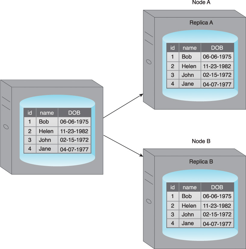
Figure 5.7 An example of replication where a dataset is replicated to Node A and Node B, resulting in Replica A and Replica B.
Master-Slave
During master-slave replication, nodes are arranged in a master-slave configuration, and all data is written to a master node. Once saved, the data is replicated over to multiple slave nodes. All external write requests, including insert, update and delete, occur on the master node, whereas read requests can be fulfilled by any slave node. In Figure 5.8, writes are managed by the master node and data can be read from either Slave A or Slave B.

Figure 5.8 An example of master-slave replication where Master A is the single point of contact for all writes, and data can be read from Slave A and Slave B.
Master-slave replication is ideal for read intensive loads rather than write intensive loads since growing read demands can be managed by horizontal scaling to add more slave nodes. Writes are consistent, as all writes are coordinated by the master node. The implication is that write performance will suffer as the amount of writes increases. If the master node fails, reads are still possible via any of the slave nodes.
A slave node can be configured as a backup node for the master node. In the event that the master node fails, writes are not supported until a master node is reestablished. The master node is either resurrected from a backup of the master node, or a new master node is chosen from the slave nodes.
One concern with master-slave replication is read inconsistency, which can be an issue if a slave node is read prior to an update to the master being copied to it. To ensure read consistency, a voting system can be implemented where a read is declared consistent if the majority of the slaves contain the same version of the record. Implementation of such a voting system requires a reliable and fast communication mechanism between the slaves.
Figure 5.9 illustrates a scenario where read inconsistency occurs.
1. User A updates data.
2. The data is copied over to Slave A by the Master.
3. Before the data is copied over to Slave B, User B tries to read the data from Slave B, which results in an inconsistent read.
4. The data will eventually become consistent when Slave B is updated by the Master.

Peer-to-Peer
With peer-to-peer replication, all nodes operate at the same level. In other words, there is not a master-slave relationship between the nodes. Each node, known as a peer, is equally capable of handling reads and writes. Each write is copied to all peers, as illustrated in Figure 5.10.

Figure 5.10 Writes are copied to Peers A, B and C simultaneously. Data is read from Peer A, but it can also be read from Peers B or C.
Peer-to-peer replication is prone to write inconsistencies that occur as a result of a simultaneous update of the same data across multiple peers. This can be addressed by implementing either a pessimistic or optimistic concurrency strategy.
• Pessimistic concurrency is a proactive strategy that prevents inconsistency. It uses locking to ensure that only one update to a record can occur at a time. However, this is detrimental to availability since the database record being updated remains unavailable until all locks are released.
• Optimistic concurrency is a reactive strategy that does not use locking. Instead, it allows inconsistency to occur with knowledge that eventually consistency will be achieved after all updates have propagated.
With optimistic concurrency, peers may remain inconsistent for some period of time before attaining consistency. However, the database remains available as no locking is involved. Like master-slave replication, reads can be inconsistent during the time period when some of the peers have completed their updates while others perform their updates. However, reads eventually become consistent when the updates have been executed on all peers.
To ensure read consistency, a voting system can be implemented where a read is declared consistent if the majority of the peers contain the same version of the record. As previously indicated, implementation of such a voting system requires a reliable and fast communication mechanism between the peers.
Figure 5.11 demonstrates a scenario where an inconsistent read occurs.
1. User A updates data.
2. a. The data is copied over to Peer A.
b. The data is copied over to Peer B.
3. Before the data is copied over to Peer C, User B tries to read the data from Peer C, resulting in an inconsistent read.
4. The data will eventually be updated on Peer C, and the database will once again become consistent.

Sharding and Replication
To improve on the limited fault tolerance offered by sharding, while additionally benefiting from the increased availability and scalability of replication, both sharding and replication can be combined, as shown in Figure 5.12.

Figure 5.12 A comparison of sharding and replication that shows how a dataset is distributed between two nodes with the different approaches.
This section covers the following combinations:
• sharding and master-slave replication
• sharding and peer-to-peer replication
Combining Sharding and Master-Slave Replication
When sharding is combined with master-slave replication, multiple shards become slaves of a single master, and the master itself is a shard. Although this results in multiple masters, a single slave-shard can only be managed by a single master-shard.
Write consistency is maintained by the master-shard. However, if the master-shard becomes non-operational or a network outage occurs, fault tolerance with regards to write operations is impacted. Replicas of shards are kept on multiple slave nodes to provide scalability and fault tolerance for read operations.
In Figure 5.13:
• Each node acts both as a master and a slave for different shards.
• Writes (id = 2) to Shard A are regulated by Node A, as it is the master for Shard A.
• Node A replicates data (id = 2) to Node B, which is a slave for Shard A.
• Reads (id = 4) can be served directly by either Node B or Node C as they each contain Shard B.

Combining Sharding and Peer-to-Peer Replication
When combining sharding with peer-to-peer replication, each shard is replicated to multiple peers, and each peer is only responsible for a subset of the overall dataset. Collectively, this helps achieve increased scalability and fault tolerance. As there is no master involved, there is no single point of failure and fault-tolerance for both read and write operations is supported.
In Figure 5.14:
• Each node contains replicas of two different shards.
• Writes (id = 3) are replicated to both Node A and Node C (Peers) as they are responsible for Shard C.
• Reads (id = 6) can be served by either Node B or Node C as they each contain Shard B.

CAP Theorem
The Consistency, Availability, and Partition tolerance (CAP) theorem, also known as Brewer’s theorem, expresses a triple constraint related to distributed database systems. It states that a distributed database system, running on a cluster, can only provide two of the following three properties:
• Consistency – A read from any node results in the same data across multiple nodes (Figure 5.15).

Figure 5.15 Consistency: all three users get the same value for the amount column even though three different nodes are serving the record.
• Availability – A read/write request will always be acknowledged in the form of a success or a failure (Figure 5.16).

Figure 5.16 Availability and partition tolerance: in the event of a communication failure, requests from both users are still serviced (1, 2). However, with User B, the update fails as the record with id = 3 has not been copied over to Peer C. The user is duly notified (3) that the update has failed.
• Partition tolerance – The database system can tolerate communication outages that split the cluster into multiple silos and can still service read/write requests (Figure 5.16).
The following scenarios demonstrate why only two of the three properties of the CAP theorem are simultaneously supportable. To aid this discussion, Figure 5.17 provides a Venn diagram showing the areas of overlap between consistency, availability and partition tolerance.

If consistency (C) and availability (A) are required, available nodes need to communicate to ensure consistency (C). Therefore, partition tolerance (P) is not possible.
If consistency (C) and partition tolerance (P) are required, nodes cannot remain available (A) as the nodes will become unavailable while achieving a state of consistency (C).
If availability (A) and partition tolerance (P) are required, then consistency (C) is not possible because of the data communication requirement between the nodes. So, the database can remain available (A) but with inconsistent results.
In a distributed database, scalability and fault tolerance can be improved through additional nodes, although this challenges consistency (C). The addition of nodes can also cause availability (A) to suffer due to the latency caused by increased communication between nodes.
Distributed database systems cannot be 100% partition tolerant (P). Although communication outages are rare and temporary, partition tolerance (P) must always be supported by a distributed database; therefore, CAP is generally a choice between choosing either C+P or A+P. The requirements of the system will dictate which is chosen.
ACID
ACID is a database design principle related to transaction management. It is an acronym that stands for:
• atomicity
• consistency
• isolation
• durability
ACID is a transaction management style that leverages pessimistic concurrency controls to ensure consistency is maintained through the application of record locks. ACID is the traditional approach to database transaction management as it is leveraged by relational database management systems.
Atomicity ensures that all operations will always succeed or fail completely. In other words, there are no partial transactions.
The following steps are illustrated in Figure 5.18:
1. A user attempts to update three records as a part of a transaction.
2. Two records are successfully updated before the occurrence of an error.
3. As a result, the database roll backs any partial effects of the transaction and puts the system back to its prior state.

Consistency ensures that the database will always remain in a consistent state by ensuring that only data that conforms to the constraints of the database schema can be written to the database. Thus a database that is in a consistent state will remain in a consistent state following a successful transaction.
In Figure 5.19:
1. A user attempts to update the amount column of the table that is of type float with a varchar value.
2. The database applies its validation check and rejects this update because the value violates the constraint checks for the amount column.

Isolation ensures that the results of a transaction are not visible to other operations until it is complete.
In Figure 5.20:
1. User A attempts to update two records as part of a transaction.
2. The database successfully updates the first record.
3. However, before it can update the second record, User B attempts to update the same record. The database does not permit User B’s update until User A’s update succeeds or fails in full. This occurs because the record with id3 is locked by the database until the transaction is complete.

Durability ensures that the results of an operation are permanent. In other words, once a transaction has been committed, it cannot be rolled back. This is irrespective of any system failure.
In Figure 5.21:
1. A user updates a record as part of a transaction.
2. The database successfully updates the record.
3. Right after this update, a power failure occurs. The database maintains its state while there is no power.
4. The power is resumed.
5. The database serves the record as per last update when requested by the user.
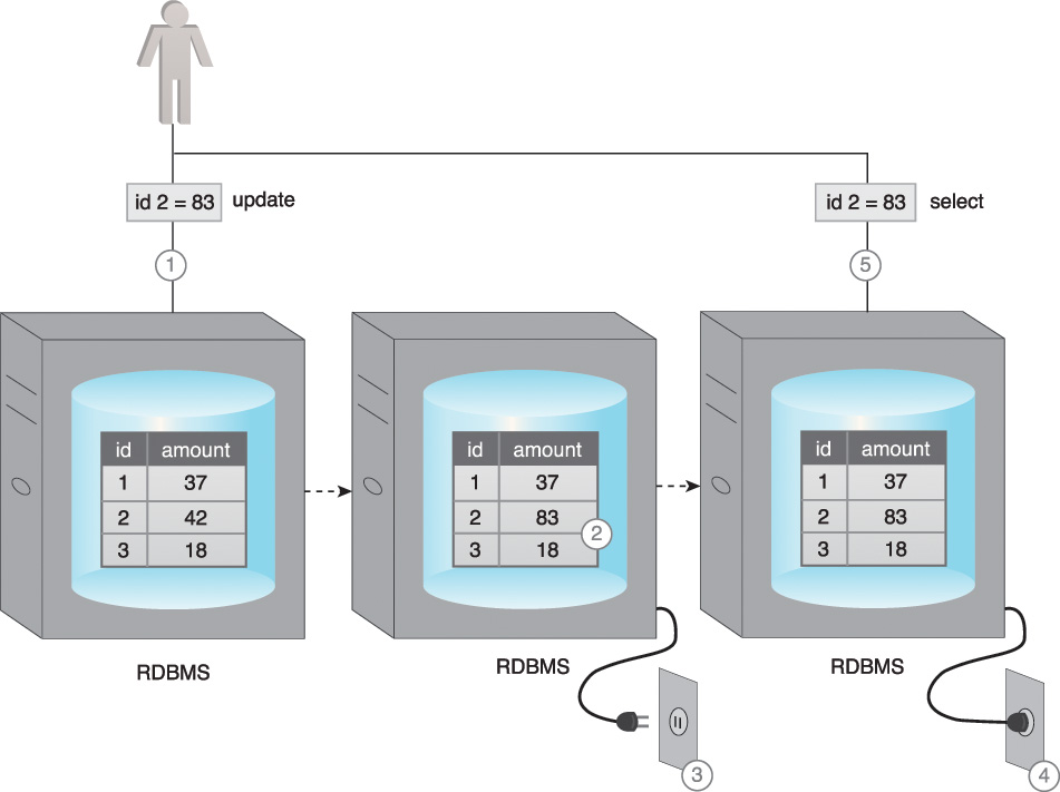
Figure 5.22 shows the results of the application of the ACID principle:
1. User A attempts to update a record as part of a transaction.
2. The database validates the value and the update is successfully applied.
3. After the successful completion of the transaction, when Users B and C request the same record, the database provides the updated value to both the users.

BASE
BASE is a database design principle based on the CAP theorem and leveraged by database systems that use distributed technology. BASE stands for:
• basically available
• soft state
• eventual consistency
When a database supports BASE, it favors availability over consistency. In other words, the database is A+P from a CAP perspective. In essence, BASE leverages optimistic concurrency by relaxing the strong consistency constraints mandated by the ACID properties.
If a database is “basically available,” that database will always acknowledge a client’s request, either in the form of the requested data or a success/failure notification.
In Figure 5.23, the database is basically available, even though it has been partitioned as a result of a network failure.

Figure 5.23 User A and User B receive data despite the database being partitioned by a network failure.
Soft state means that a database may be in an inconsistent state when data is read; thus, the results may change if the same data is requested again. This is because the data could be updated for consistency, even though no user has written to the database between the two reads. This property is closely related to eventual consistency.
In Figure 5.24:
1. User A updates a record on Peer A.
2. Before the other peers are updated, User B requests the same record from Peer C.
3. The database is now in a soft state, and stale data is returned to User B.

Eventual consistency is the state in which reads by different clients, immediately following a write to the database, may not return consistent results. The database only attains consistency once the changes have been propagated to all nodes. While the database is in the process of attaining the state of eventual consistency, it will be in a soft state.
In Figure 5.25:
1. User A updates a record.
2. The record only gets updated at Peer A, but before the other peers can be updated, User B requests the same record.
3. The database is now in a soft state. Stale data is returned to User B from Peer C.
4. However, the consistency is eventually attained, and User C gets the correct value.

BASE emphasizes availability over immediate consistency, in contrast to ACID, which ensures immediate consistency at the expense of availability due to record locking. This soft approach toward consistency allows BASE compliant databases to serve multiple clients without any latency albeit serving inconsistent results. However, BASE-compliant databases are not useful for transactional systems where lack of consistency is a concern.