
Chapter 7. Big Data Storage Technology

Storage technology has continued to evolve over time, moving from inside the server to out on the network. Today’s push to converged architecture puts compute, storage, memory and network back into the box, where the architecture can be uniformly administered. Amidst these changes, the need to store Big Data has radically altered the relational, database-centric view that has been embraced by Enterprise ICT since the late 1980s. The bottom line is that relational technology is simply not scalable in a manner to support Big Data volumes. Not to mention, businesses can find genuine value in processing semi-structured and unstructured data, which are generally incompatible with relational approaches.
Big Data has pushed the storage boundary to unified views of the available memory and disk storage of a cluster. If more storage is needed, horizontal scalability allows the expansion of the cluster through the addition of more nodes. The fact that this is equally true for both memory and disk devices is important as innovative approaches deliver realtime analytics via in-memory storage. Even batch-based processing has accelerated by the performance of Solid State Drives (SSDs), which have become less expensive.
This chapter delves deeper into the use of on-disk and in-memory storage devices for Big Data. Topics ranging from simple notions of distributed files systems for flat file storage to NoSQL devices for unstructured and semi-structured data are covered. Specifically, the different varieties of NoSQL database technologies and their appropriate uses are explained. The last major topic of the chapter is in-memory storage, which facilitates the processing of streaming data and can hold entire databases. These technologies enable a shift from traditional on-disk, batch-oriented processing to in-memory realtime processing.
On-Disk Storage Devices
On-disk storage generally utilizes low cost hard-disk drives for long-term storage. On-disk storage can be implemented via a distributed file system or a database as shown in Figure 7.1.

Distributed File Systems
Distributed file systems, like any file system, are agnostic to the data being stored and therefore support schema-less data storage. In general, a distributed file system storage device provides out of box redundancy and high availability by copying data to multiple locations via replication.
A storage device that is implemented with a distributed file system provides simple, fast access data storage that is capable of storing large datasets that are non-relational in nature, such as semi-structured and unstructured data. Although based on straightforward file locking mechanisms for concurrency control, it provides fast read/write capability, which addresses the velocity characteristic of Big Data.
A distributed file system is not ideal for datasets comprising a large number of small files as this creates excessive disk-seek activity, slowing down the overall data access. There is also more overhead involved in processing multiple smaller files, as dedicated processes are generally spawned by the processing engine at runtime for processing each file before the results are synchronized from across the cluster.
Due to these limitations, distributed file systems work best with fewer but larger files accessed in a sequential manner. Multiple smaller files are generally combined into a single file to enable optimum storage and processing. This allows the distributed file systems to have increased performance when data must be accessed in streaming mode with no random reads and writes (Figure 7.2).

Figure 7.2 A distributed file system accessing data in streaming mode with no random reads and writes.
A distributed file system storage device is suitable when large datasets of raw data are to be stored or when archiving of datasets is required. In addition, it provides an inexpensive storage option for storing large amounts of data over a long period of time that needs to remain online. This is because more disks can simply be added to the cluster without needing to offload the data to offline data storage, such as tapes. It should be noted that distributed file systems do not provide the ability to search the contents of files as standard out-of-the-box capability.
RDBMS Databases
Relational database management systems (RDBMSs) are good for handling transactional workloads involving small amounts of data with random read/write properties. RDBMSs are ACID-compliant, and, to honor this compliance, they are generally restricted to a single node. For this reason, RDBMSs do not provide out-of-the-box redundancy and fault tolerance.
To handle large volumes of data arriving at a fast pace, relational databases generally need to scale. RDBMSs employ vertical scaling, not horizontal scaling, which is a more costly and disruptive scaling strategy. This makes RDBMSs less than ideal for long-term storage of data that accumulates over time.
Note that some relational databases, for example IBM DB2 pureScale, Sybase ASE Cluster Edition, Oracle Real Application Clusters (RAC) and Microsoft Parallel Data Warehouse (PDW), are capable of being run on clusters (Figure 7.3). However, these database clusters still use shared storage that can act as a single point of failure.

Figure 7.3 A clustered rational database uses a shared storage architecture, which is a potential single point of failure that affects the availability of the database.
Relational databases need to be manually sharded, mostly using application logic. This means that the application logic needs to know which shard to query in order to get the required data. This further complicates data processing when data from multiple shards is required.
The following steps are shown in Figure 7.4:
1. A user writes a record (id = 2).
2. The application logic determines which shard it should be written to.
3. It is sent to the shard determined by the application logic.
4. The user reads a record (id = 4), and the application logic determines which shard contains the data.
5. The data is read and returned to the application.
6. The application then returns the record to the user.

The following steps are shown in Figure 7.5:
1. A user requests multiple records (id = 1, 3) and the application logic is used to determine which shards need to be read.
2. It is determined by the application logic that both Shard A and Shard B need to be read.
3. The data is read and joined by the application.
4. Finally, the data is returned to the user.

Figure 7.5 An example of the use of the application logic to join data retrieved from multiple shards.
Relational databases generally require data to adhere to a schema. As a result, storage of semi-structured and unstructured data whose schemas are non-relational is not directly supported. Furthermore, with a relational database schema conformance is validated at the time of data insert or update by checking the data against the constraints of the schema. This introduces overhead that creates latency.
This latency makes relational databases a less than ideal choice for storing high velocity data that needs a highly available database storage device with fast data write capability. As a result of its shortcomings, a traditional RDBMS is generally not useful as the primary storage device in a Big Data solution environment.
NoSQL Databases
Not-only SQL (NoSQL) refers to technologies used to develop next generation non-relational databases that are highly scalable and fault-tolerant. The symbol used to represent NoSQL databases is shown in Figure 7.6.

Characteristics
Below is a list of the principal features of NoSQL storage devices that differentiate them from traditional RDBMSs. This list should only be considered a general guide, as not all NoSQL storage devices exhibit all of these features.
• Schema-less data model – Data can exist in its raw form.
• Scale out rather than scale up – More nodes can be added to obtain additional storage with a NoSQL database, in contrast to having to replace the existing node with a better, higher performance/capacity one.
• Highly available – This is built on cluster-based technologies that provide fault tolerance out of the box.
• Lower operational costs – Many NoSQL databases are built on Open Source platforms with no licensing costs. They can often be deployed on commodity hardware.
• Eventual consistency – Data reads across multiple nodes but may not be consistent immediately after a write. However, all nodes will eventually be in a consistent state.
• BASE, not ACID – BASE compliance requires a database to maintain high availability in the event of network/node failure, while not requiring the database to be in a consistent state whenever an update occurs. The database can be in a soft/inconsistent state until it eventually attains consistency. As a result, in consideration of the CAP theorem, NoSQL storage devices are generally AP or CP.
• API driven data access – Data access is generally supported via API based queries, including RESTful APIs, whereas some implementations may also provide SQL-like query capability.
• Auto sharding and replication – To support horizontal scaling and provide high availability, a NoSQL storage device automatically employs sharding and replication techniques where the dataset is partitioned horizontally and then copied to multiple nodes.
• Integrated caching – This removes the need for a third-party distributed caching layer, such as Memcached.
• Distributed query support – NoSQL storage devices maintain consistent query behavior across multiple shards.
• Polyglot persistence – The use of NoSQL storage does not mandate retiring traditional RDBMSs. In fact, both can be used at the same time, thereby supporting polyglot persistence, which is an approach of persisting data using different types of storage technologies within the same solution architecture. This is good for developing systems requiring structured as well as semi/unstructured data.
• Aggregate-focused – Unlike relational databases that are most effective with fully normalized data, NoSQL storage devices store de-normalized aggregated data (an entity containing merged, often nested, data for an object) thereby eliminating the need for joins and extensive mapping between application objects and the data stored in the database. One exception, however, is that graph database storage devices (introduced shortly) are not aggregate-focused.
Rationale
The emergence of NoSQL storage devices can primarily be attributed to the volume, velocity and variety characteristics of Big Data datasets.
Volume
The storage requirement of ever increasing data volumes commands the use of databases that are highly scalable while keeping costs down for the business to remain competitive. NoSQL storage devices fulfill this requirement by providing scale out capability while using inexpensive commodity servers.
Velocity
The fast influx of data requires databases with fast access data write capability. NoSQL storage devices enable fast writes by using schema-on-read rather than schema-on-write principle. Being highly available, NoSQL storage devices can ensure that write latency does not occur because of node or network failure.
Variety
A storage device needs to handle different data formats including documents, emails, images and videos and incomplete data. NoSQL storage devices can store these different forms of semi-structured and unstructured data formats. At the same time, NoSQL storage devices are able to store schema-less data and incomplete data with the added ability of making schema changes as the data model of the datasets evolve. In other words, NoSQL databases support schema evolution.
Types
NoSQL storage devices can mainly be divided into four types based on the way they store data, as shown in Figures 7.7–7.10:
• key-value
• document
• column-family
• graph


Key-Value
Key-value storage devices store data as key-value pairs and act like hash tables. The table is a list of values where each value is identified by a key. The value is opaque to the database and is typically stored as a BLOB. The value stored can be any aggregate, ranging from sensor data to videos.
Value look-up can only be performed via the keys as the database is oblivious to the details of the stored aggregate. Partial updates are not possible. An update is either a delete or an insert operation.
Key-value storage devices generally do not maintain any indexes, therefore writes are quite fast. Based on a simple storage model, key-value storage devices are highly scalable.
As keys are the only means of retrieving the data, the key is usually appended with the type of the value being saved for easy retrieval. An example of this is 123_sensor1.
To provide some structure to the stored data, most key-value storage devices provide collections or buckets (like tables) into which key-value pairs can be organized. A single collection can hold multiple data formats, as shown in Figure 7.11. Some implementations support compressing values for reducing the storage footprint. However, this introduces latency at read time, as the data needs to be decompressed first before being returned.

A key-value storage device is appropriate when:
• unstructured data storage is required
• high performance read/writes are required
• the value is fully identifiable via the key alone
• value is a standalone entity that is not dependent on other values
• values have a comparatively simple structure or are binary
• query patterns are simple, involving insert, select and delete operations only
• stored values are manipulated at the application layer
A key-value storage device is inappropriate when:
• applications require searching or filtering data using attributes of the stored value
• relationships exist between different key-value entries
• a group of keys’ values need to be updated in a single transaction
• multiple keys require manipulation in a single operation
• schema consistency across different values is required
• update to individual attributes of the value is required
Examples of key-value storage devices include Riak, Redis, and Amazon Dynamo DB.
Document
Document storage devices also store data as key-value pairs. However, unlike key-value storage devices, the stored value is a document that can be queried by the database. These documents can have a complex nested structure, such as an invoice, as shown in Figure 7.12. The documents can be encoded using either a text-based encoding scheme, such as XML or JSON, or using a binary encoding scheme, such as BSON (Binary JSON).

Like key-value storage devices, most document storage devices provide collections or buckets (like tables) into which key-value pairs can be organized. The main differences between document storage devices and key-value storage devices are as follows:
• document storage devices are value-aware
• the stored value is self-describing; the schema can be inferred from the structure of the value or a reference to the schema for the document is included in the value
• a select operation can reference a field inside the aggregate value
• a select operation can retrieve a part of the aggregate value
• partial updates are supported; therefore a subset of the aggregate can be updated
• indexes that speed up searches are generally supported
Each document can have a different schema; therefore, it is possible to store different types of documents in the same collection or bucket. Additional fields can be added to a document after the initial insert, thereby providing flexible schema support.
It should be noted that document storage devices are not limited to storing data that occurs in the form of actual documents, such as an XML file, but they can also be used to store any aggregate that consists of a collection of fields having a flat or a nested schema. See Figure 7.12, which shows JSON documents being stored in a document NoSQL database.
A document storage device is appropriate when:
• storing semi-structured document-oriented data comprising flat or nested schema
• schema evolution is a requirement as the structure of the document is either unknown or is likely to change
• applications require a partial update of the aggregate stored as a document
• searches need to be performed on different fields of the documents
• storing domain objects, such as customers, in serialized object form
• query patterns involve insert, select, update and delete operations
A document storage device is inappropriate when:
• multiple documents need to be updated as part of a single transaction
• performing operations that need joins between multiple documents or storing data that is normalized
• schema enforcement for achieving consistent query design is required as the document structure may change between successive query runs, which will require restructuring the query
• the stored value is not self-describing and does not have a reference to a schema
• binary data needs to be stored
Examples of document storage devices include MongoDB, CouchDB, and Terrastore.
Column-Family
Column-family storage devices store data much like a traditional RDBMS but group related columns together in a row, resulting in column-families (Figure 7.13). Each column can be a collection of related columns itself, referred to as a super-column.

Figure 7.13 The highlighted columns depict the flexible schema feature supported by the column-family databases, where each row can have a different set of columns.
Each super-column can contain an arbitrary number of related columns that are generally retrieved or updated as a single unit. Each row consists of multiple column-families and can have a different set of columns, thereby manifesting flexible schema support. Each row is identified by a row key.
Column-family storage devices provide fast data access with random read/write capability. They store different column-families in separate physical files, which improves query responsiveness as only the required column-families are searched.
Some column-family storage devices provide support for selectively compressing column-families. Leaving searchable column-families uncompressed can make queries faster because the target column does not need to be decompressed for lookup. Most implementations support data versioning while some support specifying an expiry time for column data. When the expiry time has passed, the data is automatically removed.
A column-family storage device is appropriate when:
• realtime random read/write capability is needed and data being stored has some defined structure
• data represents a tabular structure, each row consists of a large number of columns and nested groups of interrelated data exist
• support for schema evolution is required as column families can be added or removed without any system downtime
• certain fields are mostly accessed together, and searches need to be performed using field values
• efficient use of storage is required when the data consists of sparsely populated rows since column-family databases only allocate storage space if a column exists for a row. If no column is present, no space is allocated.
• query patterns involve insert, select, update and delete operations
A column-family storage device is inappropriate when:
• relational data access is required; for example, joins
• ACID transactional support is required
• binary data needs to be stored
• SQL-compliant queries need to be executed
• query patterns are likely to change frequently because that could initiate a corresponding restructuring of how column-families are arranged
Examples of column-family storage devices include Cassandra, HBase and Amazon SimpleDB.
Graph
Graph storage devices are used to persist inter-connected entities. Unlike other NoSQL storage devices, where the emphasis is on the structure of the entities, graph storage devices place emphasis on storing the linkages between entities (Figure 7.14).

Entities are stored as nodes (not to be confused with cluster nodes) and are also called vertices, while the linkages between entities are stored as edges. In RDBMS parlance, each node can be thought of a single row while the edge denotes a join.
Nodes can have more than one type of link between them through multiple edges. Each node can have attribute data as key-value pairs, such as a customer node with ID, name and age attributes.
Each edge can have its own attribute data as key-value pairs, which can be used to further filter query results. Having multiple edges are similar to defining multiple foreign keys in an RDBMS; however, not every node is required to have the same edges. Queries generally involve finding interconnected nodes based on node attributes and/or edge attributes, commonly referred to as node traversal. Edges can be unidirectional or bidirectional, setting the node traversal direction. Generally, graph storage devices provide consistency via ACID compliance.
The degree of usefulness of a graph storage device depends on the number and types of edges defined between the nodes. The greater the number and more diverse the edges are, the more diverse the types of queries it can handle. As a result, it is important to comprehensively capture the types of relations that exist between the nodes. This is not only true for existing usage scenarios, but also for exploratory analysis of data.
Graph storage devices generally allow adding new types of nodes without making changes to the database. This also enables defining additional links between nodes as new types of relationships or nodes appear in the database.
A graph storage device is appropriate when:
• interconnected entities need to be stored
• querying entities based on the type of relationship with each other rather than the attributes of the entities
• finding groups of interconnected entities
• finding distances between entities in terms of the node traversal distance
• mining data with a view toward finding patterns
A graph storage device is inappropriate when:
• updates are required to a large number of node attributes or edge attributes, as this involves searching for nodes or edges, which is a costly operation compared to performing node traversals
• entities have a large number of attributes or nested data—it is best to store lightweight entities in a graph storage device while storing the rest of the attribute data in a separate non-graph NoSQL storage device
• binary storage is required
• queries based on the selection of node/edge attributes dominate node traversal queries
Examples include Neo4J, Infinite Graph and OrientDB.
NewSQL Databases
NoSQL storage devices are highly scalable, available, fault-tolerant and fast for read/write operations. However, they do not provide the same transaction and consistency support as exhibited by ACID compliant RDBMSs. Following the BASE model, NoSQL storage devices provide eventual consistency rather than immediate consistency. They therefore will be in a soft state while reaching the state of eventual consistency. As a result, they are not appropriate for use when implementing large scale transactional systems.
NewSQL storage devices combine the ACID properties of RDBMS with the scalability and fault tolerance offered by NoSQL storage devices. NewSQL databases generally support SQL compliant syntax for data definition and data manipulation operations, and they often use a logical relational data model for data storage.
NewSQL databases can be used for developing OLTP systems with very high volumes of transactions, for example a banking system. They can also be used for realtime analytics, for example operational analytics, as some implementations leverage in-memory storage.
As compared to a NoSQL storage device, a NewSQL storage device provides an easier transition from a traditional RDBMS to a highly scalable database due to its support for SQL.
Examples of NewSQL databases include VoltDB, NuoDB and InnoDB.
In-Memory Storage Devices
The preceding section introduced the on-disk storage device and its various types as a fundamental means of data storage. This section builds upon this knowledge by presenting in-memory storage as a means of providing options for highly performant, advanced data storage.
An in-memory storage device generally utilizes RAM, the main memory of a computer, as its storage medium to provide fast data access. The growing capacity and decreasing cost of RAM, coupled with the increasing read/write speed of solid state hard drives, has made it possible to develop in-memory data storage solutions.
Storage of data in memory eliminates the latency of disk I/O and the data transfer time between the main memory and the hard drive. This overall reduction in data read/write latency makes data processing much faster. In-memory storage device capacity can be increased massively by horizontally scaling the cluster that is hosting the in-memory storage device.
Cluster-based memory enables storage of large amounts of data, including Big Data datasets, which can be accessed considerably faster when compared with an on-disk storage device. This significantly reduces the overall execution time of Big Data analytics, thus enabling realtime Big Data analytics.
Figure 7.15 shows the symbol that represents an in-memory storage device. Figure 7.16 illustrates an access time comparison between in-memory and on-disk storage devices. The top of the figure shows that a sequential read of 1 MB of data from an in-memory storage device takes around 0.25 ms. The bottom half of the figure shows that reading the same amount of data from an on-disk storage device takes around 20 ms. This demonstrates that reading data from in-memory storage is approximately 80 times faster than on-disk storage. Note that it is assumed that the network data transfer time is the same across the two scenarios and it has therefore been excluded from the read time.


Figure 7.16 In-memory storage devices are 80 times faster at transferring data than on-disk storage devices.
An in-memory storage device enables in-memory analytics, which refers to in-memory analysis of data, such as generating statistics by executing queries on data that is stored in memory instead of on disk. In-memory analytics enable operational analytics and operational BI through fast execution of queries and algorithms.
Primarily, in-memory storage enables making sense of the fast influx of data in a Big Data environment (velocity characteristic) by providing a storage medium that facilitates realtime insight generation. This supports making quick business decisions for mitigating a threat or taking advantage of an opportunity.
A Big Data in-memory storage device is implemented over a cluster, providing high availability and redundancy. Therefore, horizontal scalability can be achieved by simply adding more nodes or memory. When compared with an on-disk storage device, an in-memory storage device is expensive because of the higher cost of memory as compared to a disk-based storage device.
Although a 64-bit machine can make use of 16 exabytes of memory, due to the physical limitations of the machine, such as the number of memory bays, the installed memory is considerably less. For scaling out, it is not just the addition of more memory, but also the addition of nodes that are required once the per node memory limit is reached. This increases the data storage cost.
Apart from being expensive, in-memory storage devices do not provide the same level of support for durable data storage. The price factor further affects the achievable capacity of an in-memory device when compared with an on-disk storage device. Consequently, only up-to-date and fresh data or data that has the most value is kept in memory, whereas stale data gets replaced with newer, fresher data.
Depending on how it is implemented, an in-memory storage device can support schema-less or schema-aware storage. Schema-less storage support is provided through key-value based data persistence.
An in-memory storage device is appropriate when:
• data arrives at a fast pace and requires realtime analytics or event stream processing
• continuous or always-on analytics is required, such as operational BI and operational analytics
• interactive query processing and realtime data visualization needs to be performed, including what-if analysis and drill-down operations
• the same dataset is required by multiple data processing jobs
• performing exploratory data analysis, as the same dataset does not need to be reloaded from disk if the algorithm changes
• data processing involves iterative access to the same dataset, such as executing graph-based algorithms
• developing low latency Big Data solutions with ACID transaction support
An in-memory storage device is inappropriate when:
• data processing consists of batch processing
• very large amounts of data need to be persisted in-memory for a long time in order to perform in-depth data analysis
• performing strategic BI or strategic analytics that involves access to very large amounts of data and involves batch data processing
• datasets are extremely large and do not fit into the available memory
• making the transition from traditional data analysis toward Big Data analysis, as incorporating an in-memory storage device may require additional skills and involves a complex setup
• an enterprise has a limited budget, as setting up an in-memory storage device may require upgrading nodes, which could either be done by node replacement or by adding more RAM
In-memory storage devices can be implemented as:
• In-Memory Data Grid (IMDG)
• In-Memory Database (IMDB)
Although both of these technologies use memory as their underlying data storage medium, what makes them distinct is the way data is stored in the memory. Key features of each of these technologies are discussed next.
In-Memory Data Grids
IMDGs store data in memory as key-value pairs across multiple nodes where the keys and values can be any business object or application data in serialized form. This supports schema-less data storage through storage of semi/unstructured data. Data access is typically provided via APIs. The symbol used to depict an IMDG is shown in Figure 7.17.
In Figure 7.18:
1. An image (a), XML data (b) and a customer object (c) are first serialized using a serialization engine.
2. They are then stored as key-value pairs in an IMDG.
3. A client requests the customer object via its key.
4. The value is then returned by the IMDG in serialized form.
5. The client then utilizes a serialization engine to deserialize the value to obtain the customer object...
6. ... in order to manipulate the customer object.

Nodes in IMDGs keep themselves synchronized and collectively provide high availability, fault tolerance and consistency. In comparison to NoSQL’s eventual consistency approach, IMDGs support immediate consistency.
As compared to relational IMDBs (discussed under IMDB), IMDGs provide faster data access as IMDGs store non-relational data as objects. Hence, unlike relational IMDBs, object-to-relational mapping is not required and clients can work directly with the domain specific objects.
IMDGs scale horizontally by implementing data partitioning and data replication and further support reliability by replicating data to at least one extra node. In case of a machine failure, IMDGs automatically re-create lost copies of data from replicas as part of the recovery process.
IMDGs are heavily used for realtime analytics because they support Complex Event Processing (CEP) via the publish-subscribe messaging model. This is achieved through a feature called continuous querying, also known as active querying, where a filter for event(s) of interest is registered with the IMDG. The IMDG then continuously evaluates the filter and whenever the filter is satisfied as a result of insert/update/delete operations, subscribing clients are informed (Figure 7.19). Notifications are sent asynchronously as change events, such as added, removed and updated events, with information about key-value pairs, such as old and new values.
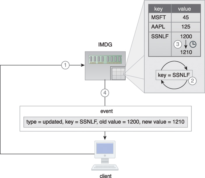
Figure 7.19 An IMDG stores stock prices where the key is the stock symbol, and the value is the stock price (shown as text for readability). A client issues a continuous query (key=SSNLF) (1) which is registered in the IMDG (2). When the stock price for SSNLF stock changes (3), an updated event is sent to the subscribing client that contains various details about the event (4).
From a functionality point of view, an IMDG is akin to a distributed cache as both provide memory-based access to frequently accessed data. However, unlike a distributed cache, an IMDG provides built in support for replication and high availability.
Realtime processing engines can make use of IMDG where high velocity data is stored in the IMDG as it arrives and is processed there before being saved to an on-disk storage device, or data from the on-disk storage device is copied to the IMDG. This makes data processing orders of magnitude faster and further enables data-reuse in case multiple jobs or iterative algorithms are run against the same data. IMDGs may also support in-memory MapReduce that helps to reduce the latency of disk based MapReduce processing, especially when the same job needs to be executed multiple times.
An IMDG can also be deployed within a cloud based environment where it provides a flexible storage medium that can scale out or scale in automatically as the storage demand increases or decreases, as shown in Figure 7.20.

Figure 7.20 An IMDG deployed in a cloud scales out automatically as the demand for data storage increases.
IMDGs can be added to existing Big Data solutions by introducing them between the existing on-disk storage device and the data processing application. However, this introduction generally requires changing the application code to implement the IMDGs API.
Note that some IMDG implementations may also provide limited or full SQL support.
Examples include In-Memory Data Fabric, Hazelcast and Oracle Coherence.
In a Big Data solution environment, IMDGs are often deployed together with on-disk storage devices that act as the backend storage. This is achieved via the following approaches that can be combined as necessary to support read/write performance, consistency and simplicity requirements:
• read-through
• write-through
• write-behind
• refresh-ahead
Read-through
If a requested value for a key is not found in the IMDG, then it is synchronously read from the backend on-disk storage device, such as a database. Upon a successful read from the backend on-disk storage device, the key-value pair is inserted into the IMDG, and the requested value is returned to the client. Any subsequent requests for the same key are then served by the IMDG directly, instead of the backend storage. Although it is a simple approach, its synchronous nature may introduce read latency. Figure 7.21 is an example of the read-through approach, where Client A tries to read key K3 (1) which does not currently exist in the IMDG. Consequently, it is read from the backend storage (2) and inserted into the IMDG (3) before being sent to Client A (4). A subsequent request for the same key by Client B (5) is then served directly by the IMDG (6).

Write-through
Any write (insert/update/delete) to the IMDG is written synchronously in a transactional manner to the backend on-disk storage device, such as a database. If the write to the backend on-disk storage device fails, the IMDG’s update is rolled back. Due to this transactional nature, data consistency is achieved immediately between the two data stores. However, this transactional support is provided at the expense of write latency as any write operation is considered complete only when feedback (write success/failure) from the backend storage is received (Figure 7.22).

Figure 7.22 A client inserts a new key-value pair (K3,V3) which is inserted into both the IMDG (1a) and the backend storage (1b) in a transactional manner. Upon successful insertion of data into the IMDG (2a) and the backend storage (2b), the client is informed that data has been successfully inserted (3).
Write-behind
Any write to the IMDG is written asynchronously in a batch manner to the backend on-disk storage device, such as a database.
A queue is generally placed between the IMDG and the backend storage for keeping track of the required changes to the backend storage. This queue can be configured to write data to the backend storage at different intervals.
The asynchronous nature increases both write performance (the write operation is considered completed as soon as it is written to the IMDG) and read performance (data can be read from the IMDG as soon as it is written to the IMDG) and scalability/availability in general.
However, the asynchronous nature introduces inconsistency until the backend storage is updated at the specified interval.
In Figure 7.23:
1. Client A updates value of K3, which is updated in the IMDG (a) and is also sent to a queue (b).
2. However, before the backend storage is updated, Client B makes a request for the same key.
3. The old value is sent.
4. After the configured interval...
5. ... the backend storage is eventually updated.
6. Client C makes a request for the same key.
7. This time, the updated value is sent.

Refresh-ahead
Refresh-ahead is a proactive approach where any frequently accessed values are automatically, asynchronously refreshed in the IMDG, provided that the value is accessed before its expiry time as configured in the IMDG. If a value is accessed after its expiry time, the value, like in the read-through approach, is synchronously read from the backend storage and updated in the IMDG before being returned to the client.
Due to its asynchronous and forward-looking nature, this approach helps achieve better read-performance and is especially useful when the same values are accessed frequently or accessed by a number of clients.
Compared to the read-through approach, where a value is served from the IMDG until its expiry, data inconsistency between the IMDG and the backend storage is minimized as values are refreshed before they expire.
In Figure 7.24:
1. Client A requests K3 before its expiry time.
2. The current value is returned from the IMDG.
3. The value is refreshed from the backend storage.
4. The value is then updated in the IMDG asynchronously.
5. After the configured expiry time, the key-value pair is evicted from the IMDG.
6. Now Client B makes a request for K3.
7. As the key does not exist in the IMDG, it is synchronously requested from the backend storage...
8. ...and updated.
9. The value is then returned to Client B.

An IMDG storage device is appropriate when:
• data needs to be readily accessible in object form with minimal latency
• data being stored is non-relational in nature such as semi-structured and unstructured data
• adding realtime support to an existing Big Data solution currently using on-disk storage
• the existing storage device cannot be replaced but the data access layer can be modified
• scalability is more important than relational storage; although IMDGs are more scalable than IMDBs (IMDBs are functionally complete databases), they do not support relational storage
Examples of IMDG storage devices include: Hazelcast, Infinispan, Pivotal GemFire and Gigaspaces XAP.
In-Memory Databases
IMDBs are in-memory storage devices that employ database technology and leverage the performance of RAM to overcome runtime latency issues that plague on-disk storage devices. The symbol for an IMDB is shown in Figure 7.25.

In Figure 7.26:
1. A relational dataset is stored into an IMDB.
2. A client requests a customer record (id = 2) via SQL.
3. The relevant customer record is then returned by the IMDB, which is directly manipulated by the client without the need for any deserialization.

An IMDB can be relational in nature (relational IMDB) for the storage of structured data, or may leverage NoSQL technology (non-relational IMDB) for the storage of semi-structured and unstructured data.
Unlike IMDGs, which generally provide data access via APIs, relational IMDBs make use of the more familiar SQL language, which helps data analysts or data scientists that do not have advanced programming skills. NoSQL-based IMDBs generally provide API-based access, which may be as simple as put, get and delete operations. Depending on the underlying implementation, some IMDBs scale-out, while others scale-up, to achieve scalability.
Not all IMDB implementations directly support durability, but instead leverage various strategies for providing durability in the face of machine failures or memory corruption. These strategies include the following:
• Use of Non-volatile RAM (NVRAM) for storing data permanently.
• Database transaction logs can be periodically stored to a non-volatile medium, such as disk.
• Snapshot files, which capture database state at a certain point in time, are saved to disk.
• An IMDB may leverage sharding and replication to support increasing availability and reliability as a substitute for durability.
• IMDBs can be used in conjunction with on-disk storage devices such as NoSQL databases and RDBMSs for durable storage.
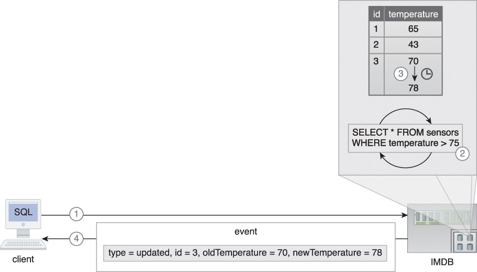
Like an IMDG, an IMDB may also support the continuous query feature, where a filter in the form of a query for data of interest is registered with the IMDB. The IMDB then continuously executes the query in an iterative manner. Whenever the query result is modified as a result of insert/update/delete operations, subscribing clients are asynchronously informed by sending out changes as events, such as added, removed and updated events, with information about record values, such as old and new values.
In Figure 7.27, an IMDB stores temperature values for various sensors. The following steps are shown:
1. A client issues a continuous query (select * from sensors where temperature > 75).
2. It is registered in the IMDB.
3. When the temperature for any sensor exceeds 75F ...
4. ... an updated event is sent to the subscribing client that contains various details about the event.
IMDBs are heavily used in realtime analytics and can further be used for developing low latency applications requiring full ACID transaction support (relational IMDB). In comparison with IMDGs, IMDBs provide an easy to set up in-memory data storage option, as IMDBs do not generally require on-disk backend storage devices.
Introduction of IMDBs into an existing Big Data solution generally requires replacement of existing on-disk storage devices, including any RDBMSs if used. In the case of replacing an RDBMS with a relational IMDB, little or no application code change is required due to SQL support provided by the relational IMDB. However, when replacing an RDBMS with a NoSQL IMDB, code change may be required due to the need to implement the IMDB’s NoSQL APIs.
In the case of replacing an on-disk NoSQL database with a relational IMDB, code change will often be required to establish SQL-based access. However, when replacing an on-disk NoSQL database with a NoSQL IMDB, code change may still be required due to the implementation of new APIs.
Relational IMDBs are generally less scalable than IMDGs, as relational IMDBs need to support distributed queries and transactions across the cluster. Some IMDB implementations may benefit from scaling up, which helps to address the latency that occurs when executing queries and transactions in a scale-out environment.
Examples include Aerospike, MemSQL, Altibase HDB, eXtreme DB and Pivotal GemFire XD.
An IMDB storage device is appropriate when:
• relational data needs to be stored in memory with ACID support
• adding realtime support to an existing Big Data solution currently using on-disk storage
• the existing on-disk storage device can be replaced with an in-memory equivalent technology
• it is required to minimize changes to the data access layer of the application code, such as when the application consists of an SQL-based data access layer
• relational storage is more important than scalability