
25
IEEE 802.16m Radio Access Technology
Sassan Ahmadi
25.2 Mobile WiMAX Network Architecture
25.3 IEEE 802.16m Protocol Structure
25.4 IEEE 802.16m MS State Diagram
25.5 Overview of IEEE 802.16m Physical Layer
Downlink Synchronization Channel (Advanced Preamble)
Multi-Antenna Techniques in IEEE 802.16m
25.6 Overview of the IEEE 802.16m MAC Layer
25.1 Introduction
The IEEE 802.16 Working Group began the development of a new amendment to the IEEE 802.16 baseline standard in January 2007 as an advanced air interface, in order to materialize the ITU-R vision for the IMT-Advanced systems as laid out in Recommendation ITU-R M.1645 [1]. The requirements for the IEEE 802.16m standard were selected to ensure competitiveness with the emerging 4th-generation radio access technologies, while extending and significantly improving the functionality and efficiency of the legacy system. The areas of improvement and extension included control/signaling mechanisms, overhead reduction, coverage of control and traffic channels at the cell-edge, downlink/uplink link budget, air-link access latency, client power consumption, transmission and detection of control channels, scan latency and network entry/reentry procedures, downlink and uplink subchannelization schemes, MAC management messages, MAC headers, support of the FDD duplex scheme, advanced single-user MIMO (SU-MIMO) and multiuser MIMO (MU-MIMO) techniques, relay, femto-cells, enhanced multicast and broadcast, enhanced location-based services, and self-configuration networks.
The IMT-Advanced requirements defined and approved by ITU-R and published as Report ITU-R M.2134 [2], referred to as target requirements in the IEEE 802.16m system requirement document [3], were evaluated based on the methodology and guidelines specified by Report ITU-R M.2135-1 [4]. The IEEE 802.16m baseline functional and performance requirements were evaluated according to the IEEE 802.16m evaluation methodology document [5]. The IMT-Advanced requirements are a subset of the IEEE 802.16m system requirements, and thus are less stringent than baseline requirements. Since satisfaction of the baseline requirements would imply a minimum-featured system, thus the minimum-performance implementation of the IEEE 802.16m can meet the IMT-Advanced requirements and can be certified as an IMT-Advanced technology. The candidate proposal submitted by the IEEE to the ITU-R in October 2009 met and exceeded the requirements of IMT-Advanced systems, and subsequently qualified as an IMT-Advanced technology [6].
This chapter describes the prominent functional features of IEEE 802.16m radio access technology including air-interface protocols, control signaling, transmission formats, and physical layer and MAC functional components.
25.2 Mobile WiMAX Network Architecture
The WiMAX Network Architecture Release 1.5 [7] specifies a nonhierarchical end-to-end network reference model (NRM) for mobile WiMAX that can be expanded to further include optional relay entities (specified by IEEE 802.16m standard) for coverage and performance enhancement. It is expected that the future releases of WiMAX network architecture will specify the reference points between the base station (BS) and relay station and between two relay stations in a multihop network.
The NRM is a logical representation of the network architecture. The NRM identifies functional entities and reference points over which interoperability is achieved. Figure 25.1 illustrates the mobile WiMAX network architecture, consisting of the following logical entities: mobile station (MS), access service network (ASN), and connectivity service network (CSN). The interfaces R1–R8 are normative reference points [7]. Each of the MS, ASN, and CSN entities represents a group of functions that can be realized in a single physical entity or may be distributed over multiple physical entities. The reference model is used to ensure interoperability among different implementations of functional entities in the network. Interoperability is verified based on the definition of logical interfaces in order to achieve an end-to-end functionality, for example, security or mobility management. Thus, the functional entities on either side of a reference point represent a collection of control or data-planes end-points. The MS is a communication device providing radio connectivity between a user terminal and a WiMAX BS that is compliant with WiMAX Forum mobile system profiles [8]. The ASN is defined as a complete set of network functions required to provide radio access to a terminal. The ASN provides the following functions:
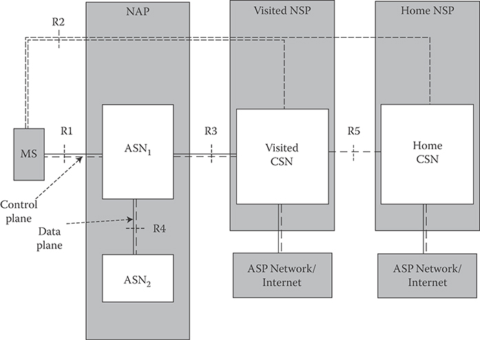
FIGURE 25.1 Mobile WiMAX NRM.
Layer-2 connectivity with the MS.
Transfer of Authentication, Authorization, and Accounting messages to subscriber's Home network service provider (H-NSP) for authentication, authorization, and session accounting for subscriber sessions.
Network discovery and selection of the subscriber's preferred NSP.
Relay functionality for establishing Layer-3 connectivity or IP address assignment to an MS.
Radio resource management (RRM).
In addition to the above functions and to support mobility, an ASN supports the following functions:
ASN-anchored mobility
CSN-anchored mobility
Paging and Idle State operation
ASN-CSN tunneling
The ASN comprises network elements such as one or more BSs and one or more ASN Gateways. An ASN may be shared by more than one CSN. The radio resource control functions in the BS would allow RRM within the BS. The CSN is defined as a set of functions that provide IP connectivity to user terminals.
25.3 IEEE 802.16m Protocol Structure
In this section, we further examine the functional elements of each protocol layer and their interactions. The 802.16m MAC common part sublayer functions are classified into radio resource control and management functional group and medium access control functional group. The control-plane functions and data-plane functions are also separately classified. As shown in Figure 25.2, the radio resource control and management functional group comprises several functional blocks including
RRM block adjusts radio network parameters related to the traffic load, and also includes the functions of load control (load balancing), admission control, and interference control.
Mobility management block scans neighbor BSs and decides whether MS should perform handover (HO) operation.
Network-entry management block controls initialization and access procedures and generates management messages during initialization and access procedures.
Location management block supports Location-Based Service (LBS), generates messages including the LBS information, and manages location update operation during idle mode.
Idle mode management block controls idle mode operation, and generates the paging advertisement message based on paging message from paging controller in the core network.
Security management block performs key management for secure communication. Using managed key, traffic encryption/decryption, and authentication are performed.
System configuration management block manages system configuration parameters, and generates broadcast control messages such as superframe headers.
Multicast and Broadcast Service (MBS) block controls and generates management messages and data associated with MBS.
Service flow and connection management block allocates Station Identifier (STID) and Flow Identifiers (FIDs) during access/HO service flow creation procedures.
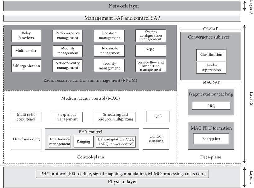
FIGURE 25.2 IEEE 802.16m protocol stack. (Adapted from Sassan Ahmadi, Mobile WiMAX; A Systems Approach to Understanding IEEE 802.16m Radio Access Technology, 1st Edition, Academic Press, 2010; IEEE 802.16m-08/0034r4, IEEE 802.16m System Description Document, (http://ieee802.org/16/tgm/index.html), December 2010.)
The medium-access control functional group, on the control plane, includes functional blocks which are related to physical layer and link controls such as
PHY control block performs PHY signaling such as ranging, channel quality measurement/feedback (CQI), and HARQ ACK or NACK signaling
Control signaling block generates resource allocation messages such as advanced medium access protocol, as well as specific control signaling messages
Sleep mode management block handles sleep mode operation and generates management messages related to sleep operation, and may communicate with the scheduler block in order to operate properly according to sleep period
Quality-of-service block performs rate control based on QoS input parameters from connection management function for each connection
Scheduling and resource multiplexing block schedules and multiplexes packets based on properties of connections
The MAC functional group on the data-plane includes functional blocks such as
Fragmentation/packing block performs fragmentation or packing of MAC service data units based on input from the scheduling and resource multiplexing block.
Automatic repeat request (ARQ) block performs MAC ARQ function. For ARQ-enabled connections, a logical ARQ block is generated from fragmented or packed MAC service data units of the same flow and sequentially numbered.
MAC protocol data unit formation block constructs MAC protocol data units such that BS/MS can transmit user traffic or management messages into PHY channels.
The IEEE 802.16m protocol structure is similar to that of the legacy system with some additional functional blocks in the control-plane for the new features including the following:
Relay functions enable relay functionalities and packet routing in relay networks.
Self-organization and self-optimization functions enable home BS or femto-cells and plug and-play form of operation for indoor BS (i.e., femto-cell).
Multicarrier functions enable control and operation of a number of adjacent or nonadjacent RF carriers (i.e., virtual wideband operation) where the RF carriers can be assigned to unicast and/or MBS s. A single MAC instantiation will be used to control several physical layers. The mobile terminal is not required to support multicarrier operation. However, if it does support multicarrier operation, it may receive control and signaling, broadcast, and synchronization channels through a primary carrier and traffic assignments (or services) via the secondary carriers.
Multiradio coexistence functions in IEEE 802.16m enable the MS to generate MAC management messages in order to report information on its collocated radio activities, and enable the BS to generate MAC management messages to respond with the appropriate actions to support multiradio coexistence operation. Furthermore, the multiradio coexistence functional block at the BS communicates with the scheduler functional block to assist proper scheduling of the MS according to the reported collocated coexistence activities. The multiradio coexistence function is independent of the sleep mode operation to enable optimal power efficiency with a high level of coexistence support.
Interference management functions are used to manage the inter-cell/sector interference effects. The procedures include MAC layer functions (e.g., interference measurement/assessment reports sent via MAC signaling and interference mitigation by scheduling and flexible frequency reuse), and PHY functions (e.g., transmit power control, interference randomization, interference cancellation, interference measurement, transmit beamforming/precoding). The inter-BS coordination functions coordinate the operation of multiple BSs by exchanging information, about interference statistics between the BSs via core-network signaling.
The carriers utilized in a multicarrier system, from perspective of a MS can be divided into two categories:
A primary RF carrier is the carrier that is used by the BS and the MS to exchange traffic and full PHY/MAC control information. The primary carrier delivers control information for proper MS operation, such as network entry. Each MS is assigned only one primary carrier in a cell.
A secondary RF carrier is an additional carrier which the BS may use for traffic allocations for MSs capable of multicarrier support. The secondary carrier may also include dedicated control signaling to support multicarrier operation.
Based on the primary and/or secondary designation, the carriers of a multicarrier system may be configured differently as follows:
Fully configured carrier: A carrier for which all control channels including synchronization, broadcast, multicast, and unicast control signaling are configured. Furthermore, information and parameters regarding multicarrier operation and the other carriers can also be included in the control channels. A primary carrier is fully configured, while a secondary carrier may be fully or partially configured depending on usage and deployment model.
Partially configured carrier: A carrier with only essential control channel configuration to support traffic exchanges during multicarrier operation.
In the event that the user terminal RF front-end and/or its baseband is not capable of processing more than one RF carrier simultaneously, the user terminal may be allowed, in certain intervals, to monitor secondary RF carriers and to resume monitoring of the primary carrier prior to transmission of the synchronization, broadcast, and common control channels.
25.4 IEEE 802.16m MS State Diagram
The IEEE 802.16m MS state diagram (i.e., a finite set of states and procedures between which the MS transit when operating in the cellular network to receive and transmit data) is defined consisting of the following states (see Figure 25.3):
Initialization State: a state where an MS without any connection performs cell selection by scanning and synchronizing to a BS preamble and acquires the system configuration information through the superframe header.
Access State: a state where the MS performs network entry to the selected BS. The MS performs the initial ranging process in order to obtain uplink synchronization. Then the MS performs basic capability negotiation with the BS. The MS later performs the authentication and authorization procedure. Next, the MS performs the registration process. The MS receives IEEE 802.16m specific user identification as part of Access State procedures. The IP address assignment may follow using appropriate procedures.
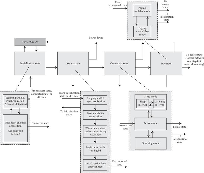
FIGURE 25.3 Mobile station state diagram. (Adapted from Sassan Ahmadi, Mobile WiMAX; A Systems Approach to Understanding IEEE 802.16m Radio Access Technology, 1st Edition, Academic Press, 2010; IEEE 802.16m-08/0034r4, IEEE 802.16m System Description Document, (http://ieee802.org/16/tgm/index.html), December 2010.)
Connected State: a state consisting of the following modes: Sleep Mode, Active Mode, and Scanning Mode. During Connected State, the MS maintains at least one transport connection and two management connections as established during Access State, while the MS and BS may establish additional transport connections. In order to reduce power consumption of the MS, the MS or BS can request a transition to sleep mode. Also, the MS can scan neighbor BSs to reselect a cell which provides more robust and reliable services.
Idle State: a state comprising two separate modes, paging available mode and paging unavailable mode. During Idle State, the MS may save power by switching between Paging Available mode and Paging Unavailable mode. In the Paging Available mode, the MS may be paged by the BS. If the MS is paged, it transitions to the Access State for its network reentry. The MS performs location update procedure during Idle State.
The MS state diagram for the IEEE 802.16m is similar to that of the legacy system with the exception of the initialization state that has been simplified to reduce the scan latency and to enable fast cell selection or reselection. The location of the essential system configuration information is fixed so that upon successful DL synchronization, the essential system configuration information can be acquired, this would enable the MS to make decision for attachment to the BS without acquiring and decoding MAC management messages and waiting for the acquisition of the system parameters, resulting in power saving in the MS due to shortening and simplification of the initialization procedure. Although both normal and fast network reentry processes are shown as transition from the Idle State to the Access State in Figure 25.3, there are differences that differentiate the two processes. The network reentry is similar to network entry, except that it may be shortened by providing the target BS with MS information through paging controller or other network entity over the backhaul.
25.5 Overview of IEEE 802.16m Physical Layer
25.5.1 Multiple Access Schemes
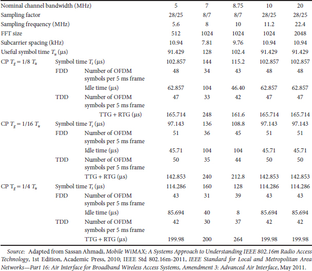
IEEE 802.16m uses OFDMA as the multiple-access scheme in downlink and uplink. It further supports both TDD and FDD duplex schemes including H-FDD operation of the MSs in the FDD networks. The majority of the frame structure attributes and baseband processing are common for both duplex schemes. The OFDMA parameters are summarized in Table 25.1. Tone dropping at both edges of the frequency band based on 10 and 20 MHz systems can be used to support other bandwidths. In Table 25.1, TTG and RTG acronyms denote transmit/receive and receive/transmit transition gaps in TDD mode of operation, respectively.
25.5.2 Frame Structure
In IEEE 802.16m, a superframe is defined as a collection of consecutive equally sized radio frames whose beginning is marked with a superframe header. The superframe header carries short-term and long-term system configuration information.
In order to decrease the air-link access latency, the radio frames are further divided into a number of subframes where each subframe comprises an integer number of OFDM symbols. The transmission time interval is defined as the transmission latency over the air-link and is equal to an integer multiple of subframe length (default is one subframe). There are four types of subframes: (1) type-1 subframe, which consists of six OFDM symbols, (2) type-2 subframe, which consists of seven OFDM symbols, (3) type-3 subframe which consists of five OFDM symbols, and (4) type-4 subframe, which consists of nine OFDM symbols. In the basic frame structure shown in Figure 25.4, superframe length is 20 ms (comprising four radio frames), radio frame size is 5 ms (comprising eight subframes), and subframe length is 0.617 ms. The use of subframe concept with the latter parameter set would reduce the one-way air-link access latency to <10 ms.
TABLE 25.1 IEEE 802.16m OFDM Parameters
Separate time–frequency regions are used to support new and legacy MSs that are time-division multiplexed across time domain in the downlink. For the uplink transmissions, both time- and frequency-division multiplexing approaches can be used to support legacy and new terminals. The nonbackward compatible features are restricted to the new zones. All backward compatible functions are used in the legacy zones. In the absence of any legacy system, the legacy zones will disappear and the entire frame will be allocated to the new zones.
Coexistence between IEEE 802.16m and 3GPP LTE in TDD mode may be facilitated by inserting either an idle symbol or idle subframes within the IEEE 802.16m frame for certain 3GPP LTE TDD configurations [6]. An operator configurable delay or offset between the beginning of an IEEE 802.16m frame and a 3GPP LTE TDD frame can be applied in some configurations to minimize the waste of radio resources consumed by idle symbols or idle subframes.
In the case where an IEEE 802.16m BS coexists with legacy BSs, the switching points are limited to two in each TDD radio frame. The support for multiple RF carriers can be accommodated with the same frame structure used for single-carrier operation. All RF carriers are time aligned at the frame, subframe, and symbol level. Alternative frame structures for CP = 1/16 and CP = 1/4 are used that incorporate different number of OFDM symbols in certain subframes or different number of subframes per frame [6,10].
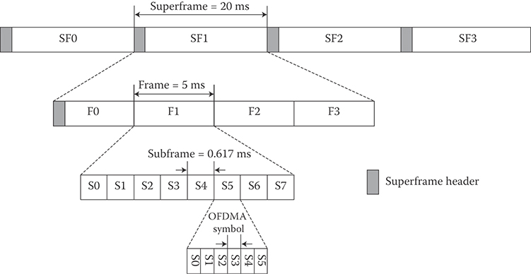
FIGURE 25.4 IEEE basic frame structure. (Adapted from Sassan Ahmadi, Mobile WiMAX; A Systems Approach to Understanding IEEE 802.16m Radio Access Technology, 1st Edition, Academic Press, 2010; IEEE Std 802.16m-2011, IEEE Standard for Local and Metropolitan Area Networks—Part 16: Air Interface for Broadband Wireless Access Systems, Amendment 3: Advanced Air Interface, May 2011.)
25.5.3 Subchannelization Schemes
The downlink/uplink subframes are divided into a number of frequency partitions, where each partition consists of a set of physical resource units (PRU) over the available number of OFDM symbols in the subframe. Each frequency partition can include localized and/or distributed PRUs. This is different from the legacy system where each zone can only accommodate localized or distributed subchannels. Frequency partitions can be used for different purposes such as fractional frequency reuse (FFR). The downlink/uplink resource partitioning and mapping procedure is illustrated in Figure 25.5.
25.5.3.1 Downlink Resource Structure
A PRU is the basic physical unit for resource allocation that comprises Psc contiguous subcarriers by Nsym contiguous OFDM symbols where Psc is 18 subcarriers and Nsym is 6, 7, or 5 OFDM symbols for type-1, type-2, or type-3 subframes, respectively. A logical resource unit (LRU) is the basic logical unit for distributed and localized resource allocations. A LRU comprises Psc × Nsym subcarriers.
Distributed resource units (DRU) are used to achieve frequency diversity gain. A DRU contains a group of subcarriers which are spread across a frequency partition. The size of the DRUs is equal to that of PRU. The minimum unit for forming a DRU in the downlink is equal to a pair of subcarriers also known as a tone-pair. Localized or Contiguous resource units (CRU) are used to achieve frequency-selective scheduling gain. A localized resource unit comprises a group of subcarriers which are contiguous across frequency. The size of the localized resource units is equal to that of the PRUs. To form distributed and localized resource units, the subcarriers over the OFDM symbols of a subframe are partitioned into guard and used subcarriers. The DC subcarrier is not used. The used subcarriers are grouped into integer number of PRUs. Each PRU contains pilots and data subcarriers. The number of used pilot and data subcarriers depends on MIMO mode, rank and number of multiplexed MSs over the resource block, as well as the number of OFDM symbols within a subframe.
The PRUs are subsequently divided into subbands and mini-bands where a subband comprises N1 adjacent PRUs and a mini-band comprises N2 adjacent PRUs, where N1 = 4 and N2 = 1. The subbands are suitable for frequency-selective allocations as they provide a contiguous allocation of PRUs in frequency. The mini-bands are suitable for frequency diverse allocations and are permuted in frequency. Each frequency partition is divided into localized and/or distributed resource allocations. The size of the distributed/localized groups is flexibly configured per sector. Adjacent sectors are not required to have the same configuration for the localized and distributed groups. The localized and DRUs are further mapped into LRUs by direct mapping for CRUs and by subcarrier permutation for DRUs.
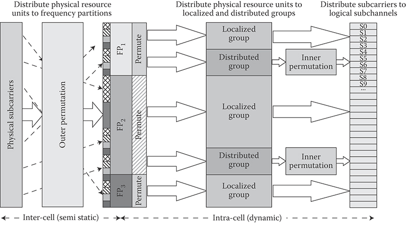
FIGURE 25.5 Illustration of the downlink/uplink subcarrier to resource unit mapping where Pi denotes the ith frequency partition. (Adapted from Sassan Ahmadi, Mobile WiMAX; A Systems Approach to Understanding IEEE 802.16m Radio Access Technology, 1st Edition, Academic Press, 2010; IEEE Std 802.16m-2011, IEEE Standard for Local and Metropolitan Area Networks—Part 16: Air Interface for Broadband Wireless Access Systems, Amendment 3: Advanced Air Interface, May 2011.)
The subcarrier permutation defined for the downlink distributed resource allocations spreads the subcarriers of the DRU across all the distributed resource allocations within a frequency partition. After mapping all pilots, the remaining used subcarriers are used to define the DRUs.
25.5.3.2 Uplink Resource Structure
Similar to the downlink subchannelization scheme, a PRU in the uplink is defined as the basic physical unit for resource allocation that comprises Psc consecutive subcarriers by Nsym consecutive OFDM symbols. The value of Psc is 18 subcarriers and the possible values of Nsym are 6, 7, 5, and 9 OFDM symbols for type-1, type-2, type-3, and type-4 subframes, respectively. An LRU is the basic logical unit for distributed and localized resource allocations whose size is Psc × Nsym subcarriers for data transmission. The subcarriers of an OFDM symbol are partitioned into Ng,left left guard subcarriers, Ng,right right guard subcarriers, and Nused used subcarriers. The DC subcarrier is not used. The Nused subcarriers are grouped into integer number of PRUs. Each PRU contains pilots and data subcarriers. The number of pilots and data subcarriers depends on MIMO mode, rank and number of MSs multiplexed over the resource block, and the type of resource allocation; that is, distributed or localized resource allocations as well as the type of the subframe.
The uplink distributed units comprise a group of subcarriers which are spread over a frequency partition. The size of distributed unit is equal to logical resource blocks. The minimum unit for constructing a DRU in the uplink is a tile. The uplink tile sizes are six subcarriers by Nsym OFDM symbols. The localized resource unit is used to achieve frequency-selective scheduling gain. A localized resource unit contains a group of subcarriers which are contiguous across frequency. The size of the localized resource unit equals the size of the LRUs for localized allocations; that is, 18 subcarriers by Nsym OFDM symbols.
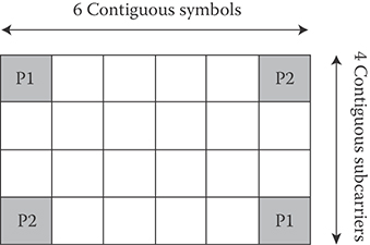
FIGURE 25.6 New uplink PUSC structure for two streams. (Adapted from Sassan Ahmadi, Mobile WiMAX; A Systems Approach to Understanding IEEE 802.16m Radio Access Technology, 1st Edition, Academic Press, 2010; IEEE Std 802.16m-2011, IEEE Standard for Local and Metropolitan Area Networks—Part 16: Air Interface for Broadband Wireless Access Systems, Amendment 3: Advanced Air Interface, May 2011.)
The PRUs are first subdivided into subbands and mini-bands, where a subband comprises N1 adjacent PRUs and a mini-band consists of N2 adjacent PRUs, where N1 = 4 and N2 = 1. The subbands are suitable for frequency-selective allocations whereas the mini-bands are suitable for frequency diverse allocation and are permuted in frequency. An inner permutation is defined for the uplink distributed resource allocations that spreads DRU tiles across the entire distributed resource allocations within a frequency partition. Each DRU in an uplink frequency partition is divided into three tiles of six adjacent subcarriers over Nsym symbols. The tiles within a frequency partition are collectively tile-permuted to obtain frequency diversity gain across the allocated resources.
The IEEE 802.16m uplink physical structure supports both frequency- and time-division multiplexing of the new and the legacy systems. A new partial use of subcarriers (PUSC) subchannelization scheme is specified for mixed mode operation with the legacy system. The new PUSC scheme contains six tiles of four subcarriers by six symbols as shown in Figure 25.6.
25.5.4 Modulation and Coding
The performance of adaptive modulation generally suffers from the power inefficiencies of multilevel modulation schemes. This is due to the variations in bit reliabilities caused by the bit-mapping onto the signal constellation. To overcome this issue, a constellation-rearrangement (CoRe) scheme is utilized where signal constellation of QAM signals between retransmissions is rearranged; that is, the mapping of the bits into the complex-valued symbols between successive HARQ retransmissions is changed, resulting in averaging bit reliabilities over several retransmissions and lower packet error rates. The mapping of bits to the constellation point depends on the CoRe type used for HARQ re-transmissions and may also depend on the MIMO scheme. The complex-valued modulated symbols are mapped to the input of the MIMO encoder. Incremental redundancy HARQ (HARQ-IR) is used in by determining the starting position of the bit selection for HARQ retransmissions.
Figure 25.7 shows the channel coding and modulation procedures. A cyclic redundancy check (CRC) is appended to a burst (i.e., a physical layer data unit) prior to partitioning. The 16-bit CRC is calculated over the entire bits in the burst. If the burst size including burst CRC exceeds the maximum block size, the burst is partitioned into KFB forward error correction (FEC) blocks, each of which is encoded separately. If a burst is partitioned into more than one FEC blocks, an FEC block CRC is appended to each FEC block before the FEC encoding. The FEC block CRC of an FEC block is calculated based on the entire bits in that FEC block. Each partitioned FEC block including 16-bit FEC block CRC has the same length. The maximum FEC block size is 4800 bits. Concatenation rules are based on the number of information bits and do not depend on the structure of the resource allocation (number of LRUs and their size). The IEEE 802.16m uses the convolutional turbo code (CTC) with code rate of 1/3 as defined in References 10 and 11. The CTC scheme is extended to support additional FEC block sizes. The FEC block sizes which are multiple of seven are removed for the tail-biting encoding structure. The encoder block depicted in Figure 25.7 includes the interleaver.

FIGURE 25.7 Coding and modulation procedures.
Bit selection and repetition are used in IEEE 802.16m to achieve rate matching. The bit selection mechanism adapts the number of coded-bits to the size of the resource unit and the subframe type. The total number of subcarriers in the allocated resource unit is divided among the designated FEC blocks. The total number of information and parity bits generated by FEC encoder are considered the maximum size of the circular buffer. The code repetition is performed when the number of transmitted bits is larger than the number of selected bits. The selection of coded bits is conducted cyclically over the buffer. The mother-code bits, the total number of information and parity bits generated by FEC encoder, are considered as the maximum size of circular buffer. If the size of the circular buffer Nbuffer is smaller than the number of mother-code bits, the first Nbuffer bits of mother-code bits are considered as the selected bits.
The QPSK, 16QAM, and 64QAM baseband modulation schemes are supported similar to that of the legacy system. The mapping of bits to the constellation points depends on the CoRe version that may be used for HARQ retransmissions depending on the MIMO scheme. The QAM symbols are mapped to the input of the MIMO encoder. The FEC block sizes specified in the standard include the additional CRC; that is, per burst and per FEC block, if applicable. Other sizes may require padding to the next larger burst size. The code rate and modulation order depend on the burst size and the resource allocation.
HARQ-IR scheme is used in IEEE 802.16m by determining the starting position of the bit selection for HARQ retransmissions. Chase Combining HARQ is also supported and considered as a special case of HARQ-IR. The 2-bit subpacket identifier is used to identify the starting position of the subpackets. The CoRe scheme can be expressed by a bit-level interleaver. The resource allocation and transmission formats in each retransmission in the downlink can be configured with control signaling. The resource allocation in each retransmission in the uplink can be fixed or adaptive as configured by control signaling. In HARQ retransmissions, the bits or symbols can be transmitted in a different order to exploit the frequency diversity of the channel. For HARQ retransmission, the mapping of bits or modulated symbols to spatial streams may be applied to exploit spatial diversity with a given mapping pattern, depending on the type of HARQ-IR. In this case, the predefined set of mapping patterns should be known to the transmitter and receiver. In the downlink HARQ, the BS may transmit coded bits exceeding current available soft buffer capacity.
25.5.5 Pilot Structure
25.5.5.1 Downlink Pilot Structure
Transmission of pilot subcarriers in the downlink is necessary to allow channel estimation, channel quality measurement (e.g., CQI), frequency offset estimation, and so on. To optimize the system performance in different propagation environments, IEEE 802.16m supports both common and dedicated pilot structures. The common pilots can be used in distributed allocations by all MSs. The dedicated pilots can be used with both localized and distributed allocations and are associated with a user-specific pilot index. The dedicated pilots are associated with a specific resource allocation and are used by the MSs assigned to specific resource block; therefore, they can be precoded or beam-formed in the same manner as the data subcarriers of the resource block. Pilot subcarriers that can be used only by a group of MSs within an FFR group are a special case of common pilots. The downlink pilot structure is defined for up to eight streams and the design of common and dedicated pilots is consistent. There is an equal pilot density per spatial stream; nevertheless, there is not necessarily equal pilot density per OFDM symbols. There is the same number of pilots for each PRU allocated to a particular MS. For the subframes consisting of 5 or 7 OFDM symbols, one of OFDM symbols is deleted or repeated. To overcome the effects of pilot interference among the neighboring sectors or BSs, an interlaced pilot structure is used by cyclically shifting the base pilot pattern such that the pilots of neighboring cells do not overlap.
The E-MBS-zone-specific pilots are transmitted for multicell multicast broadcast single-frequency network (SFN) transmissions. An E-MBS zone is a group of BSs involved in the SFN transmission. The E-MBS-zone-specific pilots are common within an E-MBS zone but different between neighboring E-MBS zones. Synchronous transmissions of the same content with common pilot from multiple BSs in an E-MBS zone would result in improved channel estimation. The E-MBS-zone-specific pilot-patterns depend on the maximum number of transmit streams. Pilot structures up to two transmit streams are supported.
25.5.5.2 Uplink Pilot Structure
The uplink pilots are dedicated to localized and DRUs and are precoded in the same manner as the data subcarriers of the resource unit. The uplink pilot structure is defined for up to four streams for SU-MIMO and up to eight streams for Collaborative Spatial Multiplexing. When pilots are power-boosted, each data subcarrier should have the same transmission power across all OFDM symbols in a resource unit. The 18×6 uplink LRUs use the same pilot patterns as the downlink counterpart. The pilot pattern for 6×6 tile structure is different and it is shown in Figure 25.8.
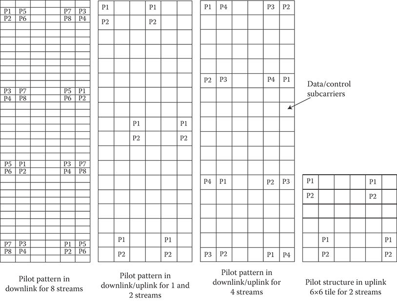
FIGURE 25.8 Downlink/uplink pilot structures for 1, 2, 4, and 8 streams for type-1 subframe.
25.5.6 Control Channels
Downlink control channels carry essential information for system operation. Depending on the type of control signaling, information is transmitted over different time intervals (i.e., from superframe to subframe intervals). The system configuration parameters are transmitted at the superframe intervals, whereas control signaling related to user data allocations is transmitted at the frame/subframe intervals. An IEEE 802.16m-compliant MS can access the network without decoding the legacy frame control header and legacy DL/UL-MAP messages [6,10].
25.5.6.1 Downlink Control Channels
25.5.6.1.1 Superframe Header
The superframe header carries essential system parameters and configuration information. The content of superframe header is divided into two parts referred to as primary and secondary superframe headers. The information transmitted in secondary superframe header is further divided into different subpackets. The primary superframe header is transmitted every superframe, whereas the secondary superframe header is transmitted over one or more superframes. The primary and secondary superframe headers are located in the first subframe within a superframe and are time-division multiplexed with the advanced preamble. The superframe header is confined to 5 MHz of bandwidth. The primary superframe header is transmitted using predetermined modulation and coding scheme. The secondary superframe header is transmitted using predetermined modulation scheme while its code repetition factor is signaled in the primary superframe header. The primary and secondary superframe headers are transmitted using two spatial streams and space–frequency block coding to improve their coverage and reliability. The MS is not required to know the antenna configuration prior to decoding the primary superframe header. The information transmitted in the secondary superframe header is divided into different subpackets. The secondary superframe header Subpacket 1 (SP1) includes information needed for network reentry. The secondary superframe header Subpacket 2 (SP2) contains information for initial network entry. The secondary superframe header Subpacket 3 (SP3) contains remaining system information for maintaining communication with the BS.
25.5.6.1.2 Advanced MAP
The advanced MAP (A-MAP) consists of both user-specific (dedicated control channel) and nonuser-specific (common control channel) control information. The nonuser-specific control information includes information that is not dedicated to a specific user or a specific group of users. It contains information required to decode user-specific control signaling. User-specific control information consists of information intended for one or more users. It includes scheduling assignment, power control, and HARQ ACK/NACK. Resources can be allocated persistently to the MSs. The periodicity of the allocation is configurable. Group control information is used to allocate resources or to configure resources to one or multiple MSs within a user group. Each group is associated with a set of radio resources. Voice over IP (VoIP) is an example of the class of services that can take advantage of group allocation messages. Within a subframe, control and data channels are frequency-division multiplexed. Both control and data channels are transmitted on LRUs that span over all OFDM symbols within a subframe [6,10].
Each downlink subframe contains a control region with both nonuser-specific and user-specific control information. All A-MAPs share a time-frequency region known as A-MAP region. The control regions are located in every subframe. The corresponding uplink allocations occurs L subframes later, where the value of L is determined by A-MAP relevance. The coding rate of the control blocks is known to the MS through group size indication in nonuser-specific control information in order to reduce the complexity of blind detection by the MS.
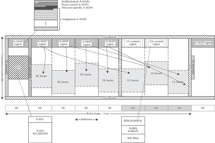
FIGURE 25.9 Structure of IEEE 802.16m overhead channels in the downlink and uplink in TDD mode (example). (Adapted from Sassan Ahmadi, Mobile WiMAX; A Systems Approach to Understanding IEEE 802.16m Radio Access Technology, 1st Edition, Academic Press, 2010.)
An A-MAP allocation information element (IE) is defined as the basic element of unicast control signaling. A unicast control IE may be addressed to one user using a unicast identifier or to multiple users via multicast/broadcast identifier. The CRC is masked with the identifier A-MAP allocation IE. It may contain information related to resource allocation, HARQ, MIMO transmission mode, and so on. Each unicast control IE is coded separately. Note that this method is different from the legacy system control mechanism where the IEs of all users are jointly coded. Nonuser-specific control information is encoded separately from the user-specific control information. The transmission format of nonuser-specific control information is predetermined. In the downlink subframes, each frequency partition may contain an A-MAP region. The A-MAP region occupies the first few DRUs in a frequency partition. The structure of an A-MAP region is illustrated in Figure 25.9. The amount of resource occupied by each A-MAP physical channel may vary depending on the system configuration and scheduling parameters. There are different types of A-MAP as follows:
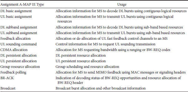
Assignment A-MAP contains resource assignment information which is categorized into multiple types of assignment A-MAP IEs. Each assignment A-MAP IE is coded separately and carries information for one or a group of users. The minimum unit of logical resources in the assignment A-MAP consists of 56 data subcarriers. Assignment A-MAP IEs with <40 bits are zero-padded to 40 bits. Assignment A-MAP IEs with >40 bits are divided into several segments, each with 40 bits. Segments of an assignment A-MAP IE are separately coded and modulated and occupy a number of logically CRUs. Assignment A-MAP IEs are grouped together based on channel coding rate. Assignment A-MAP IEs in the same group are transmitted in the same frequency partition with the same channel coding rate. Each assignment A-MAP group contains several logically CRUs.
TABLE 25.2 Assignment A-MAP IE Types and Their Usage
The number of assignment A-MAP IEs in each assignment A-MAP group is signaled through nonuser-specific A-MAP in the same subframe. If two assignment A-MAP groups using two channel coding rates are present in an A-MAP region, assignment A-MAP group using lower channel coding rate is allocated first, followed by assignment A-MAP group using higher channel coding rate. The maximum number of assignment A-MAP IEs in one subframe that the BS may allocate to an MS is 8. This number includes all the assignment A-MAP IEs that are required to be monitored by the MS. For a segmentable assignment A-MAP IE (i.e., an assignment A-MAP IE that occupies >1 minimum LRU using QPSK 1/2), each segment is counted as one assignment A-MAP IE.
HARQ Feedback A-MAP contains HARQ ACK/NACK information for uplink data transmission.
Power Control A-MAP carries power control commands to the MSs.
There are different assignment A-MAP IE types that distinguish between DL/UL, persistent/nonpersistent, single-user/group resource allocation, basic/extended IE scenarios. Different types of assignment A-MAPs and their usage are shown in Table 25.2.
25.5.6.2 Uplink Control Channels
25.5.6.2.1 MIMO Feedback
MIMO feedback provides wideband and/or narrowband spatial characteristics of the channel that are required for MIMO operation. The MIMO mode, precoding matrix index (PMI), rank adaptation information, channel covariance matrix elements, and best subband index are examples of MIMO feedback information.
25.5.6.2.2 HARQ Feedback
HARQ feedback (ACK/NACK) is used to acknowledge downlink data transmissions. The uplink HARQ feedback channel starts at a predetermined offset with respect to the corresponding downlink transmission. The HARQ feedback channel is frequency-division multiplexed with other control and data channels (see Figure 25.9). Orthogonal codes are used to multiplex multiple HARQ feedback channels. The HARQ feedback channel comprises three distributed mini-tiles.
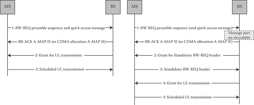
FIGURE 25.10 Bandwidth request procedure. (Adapted from Sassan Ahmadi, Mobile WiMAX; A Systems Approach to Understanding IEEE 802.16m Radio Access Technology, 1st Edition, Academic Press, 2010; IEEE Std 802.16m-2011, IEEE Standard for Local and Metropolitan Area Networks—Part 16: Air Interface for Broadband Wireless Access Systems, Amendment 3: Advanced Air Interface, May 2011.)
25.5.6.2.3 Bandwidth Request
Bandwidth requests (BW-REQ) are used to indicate the amount of bandwidth required by a user. BW-REQs are transmitted through indicators or messages. A BW-REQ indicator notifies the BS of an uplink grant request by the MS sending the indicator. BW-REQ messages can include information about the status of queued traffic at the MS such as buffer size and quality-of-service parameters. Contention- or noncontention-based random access is used to transmit BW-REQ information on this control channel. The contention-based BW-REQ procedure is illustrated in Figure 25.10. A five-step regular procedure or an optional three-step quick access procedure is used. Steps 2 and 3 can be skipped in a quick access procedure. In step 1, the MS sends a BW-REQ indicator for quick access that may indicate information such as MS addressing and/or request size and/or uplink transmit power report, and/or QoS parameters, and the BS may allocate uplink grant based on certain policy. The MS may piggyback additional BW-REQ information along with user data during uplink transmission (step 5). In steps 2 and 4, the BS acknowledges receipt of the messages as shown in Figure 25.10.
The BW-REQ channel starts at a configurable location with the configuration defined in a downlink broadcast control message. The BW-REQ channel is frequency-division multiplexed with other uplink control and data channels (see Figure 25.9). A BW-REQ tile is defined by six subcarriers over six OFDM symbols. Each BW-REQ channel consists of three distributed BW-REQ tiles. Multiple BW-REQ indicators can be transmitted on the same BW-REQ channel using code-division multiplexing.
25.5.6.2.4 Channel Quality Indicators
Channel quality feedback provides information about channel conditions as seen by the user. This information is used by the BS for link adaptation, resource allocation, power control, and so on. The channel quality measurement includes both narrowband and wideband measurements. The CQI feedback overhead can be reduced through differential feedback or other compression techniques. Examples of CQI include effective carrier-to-interference-plus-noise ratio (CINR), band selection, and so on. The default subframe size for transmission of uplink control information is six OFDM symbols. The fast feedback channel carries channel quality and MIMO feedback. There are two types of uplink fast feedback control channels known as primary and secondary fast feedback channels. The secondary fast feedback control channel carries narrowband CQI and MIMO feedback information. The secondary fast feedback channel can be used to support CQI reporting at higher code rate and thus more CQI information bits. The fast feedback channel is frequency-division multiplexed with other uplink control and data channels.
The fast feedback channel starts at a predetermined location with the size defined in a downlink broadcast control message. Fast feedback allocations to a MS can be periodic and the allocations are configurable. The specific type of feedback information carried on each fast feedback opportunity can be different. The number of bits carried in the fast feedback channel can be adaptive. For efficient transmission of feedback channels a mini-tile is defined comprising two subcarriers by six OFDM symbols. One LRU consists of nine mini-tiles and can be shared by multiple fast feedback channels [6,10].
25.5.6.2.5 Uplink Sounding Channel
The sounding channel is used by a user terminal to transmit sounding reference signals to enable the BS to measure uplink channel conditions. The sounding channel may occupy either specific uplink subbands or the entire bandwidth over one OFDM symbol. The BS can configure an MS to transmit the uplink sounding signal over predefined subcarriers within specific subbands or the entire bandwidth. The sounding channel is orthogonally multiplexed (in time or frequency) with other control and data channels. Furthermore, the BS can configure multiple user terminals to transmit sounding signals on the corresponding sounding channels using code-, frequency-, or time-division multiplexing. Power control for the sounding channel can be used to adjust the sounding signal quality. The transmit power from each mobile terminal may be separately controlled according to certain CINR target values [6,10].
25.5.6.2.6 Ranging Channel
The ranging channel is used for uplink synchronization. The ranging channel can be further classified into ranging for nonsynchronized and synchronized MSs. A random access procedure, which can be contention or noncontention based, is used for ranging. The contention-based random access is used for initial ranging. The noncontention-based random access is used for periodic ranging and HO. The ranging channel for nonsynchronized MSs starts at a configurable location with the configuration signaled in a downlink broadcast control message. The ranging channel for nonsynchronized MSs is frequency-division multiplexed with other uplink control and data channels.
The ranging channel for nonsynchronized MSs consists of three fields: (1) Ranging cyclic prefix (RCP), (2) Ranging preamble (RP), and (3) Guard time (GT). The length of RCP is longer than the sum of the maximum delay spread and round trip delay of supported cell size. The length of GT is chosen longer than the round trip delay of the supported cell size. The length of RP is chosen equal to or longer than the length of RCP. To support large cell sizes, the ranging channel for nonsynchronized user terminals can span multiple concatenated subframes. Figure 25.11 shows the two ranging channel formats. A single preamble can be used by different nonsynchronized users for increasing ranging opportunities. When the preamble is repeated as a single opportunity, the second RCP can be omitted for coverage extension. A number of guard subcarriers are reserved at the edges of nonsynchronized ranging channel physical resource.
When multiantenna transmission is supported by MS, it can be used to increase the ranging opportunity by using spatial multiplexing. The ranging channel for synchronized MSs is used for periodic ranging. The ranging channel for synchronized user terminals starts at a configurable location with the configuration signaled in a downlink broadcast control message. The ranging channel for synchronized MSs is frequency-division multiplexed with other uplink control and data channels.
25.5.6.2.7 Power Control
Power control mechanism is supported for downlink and uplink. The BS controls the transmit power per subframe and per user. Using downlink power control, user-specific information is received by the terminal with the controlled power level. The downlink A-MAPs are power-controlled based on the terminal uplink channel quality feedback. The uplink power control is supported to compensate for the path loss, shadowing, fast fading, and implementation loss as well as to mitigate intercell and intracell interference. The uplink power control includes open-loop and closed-loop power control mechanisms. The BS can transmit necessary information through control channel or message to terminals to support uplink power control. The parameters of power control algorithm are optimized on a system-wide basis by the BS and broadcasted periodically or triggered by certain events.

FIGURE 25.11 Ranging channel structure for synchronized and nonsynchronized access. (Adapted from Sassan Ahmadi, Mobile WiMAX; A Systems Approach to Understanding IEEE 802.16m Radio Access Technology, 1st Edition, Academic Press, 2010; IEEE Std 802.16m-2011, IEEE Standard for Local and Metropolitan Area Networks—Part 16: Air Interface for Broadband Wireless Access Systems, Amendment 3: Advanced Air Interface, May 2011.)
In high-mobility scenarios, power control scheme may not be able to compensate the fast fading channel effect because of the variations of the channel impulse response. As a result, the power control is used to compensate for the distance-dependent path loss, shadowing, and implementation loss only.
The channel variations and implementation loss are compensated via open-loop power control without frequently interacting with the BS. The terminal can determine the transmit power based on the transmission parameters sent by the serving BS, uplink channel transmission quality, downlink channel state information (CSI), and interference knowledge obtained from downlink. Open-loop power control provides a coarse initial power setting of the terminal when an initial connection is established.
The dynamic channel variations are compensated via closed-loop power control with power control commands from the serving BS. The BS measures uplink channel state and interference information using uplink data and/or control channel transmissions and sends power control commands to the terminal. The terminal adjusts its transmission power based on the power control commands from the BS.
25.5.7 Downlink Synchronization Channel (Advanced Preamble)
IEEE 802.16m utilizes a new hierarchical structure for the downlink synchronization where two sets of preambles at superframe and frame intervals are transmitted (Figure 25.12). The first set of preamble sequences mark the beginning of the superframe and are common to a group of sectors or cells. The primary advanced preamble carries information about system bandwidth and carrier configuration. The primary advanced preamble has a fixed bandwidth of 5 MHz and can be used to facilitate location-based services. A frequency reuse of one is applied to the primary advanced preamble in the frequency domain. The second set of advanced preamble sequences (secondary advanced preamble) is repeated every 10 ms and spans the entire system bandwidth and carries the physical cell identifier. A frequency reuse of three is used for this set of sequences to mitigate intercell interference. The secondary advanced preambles carry 768 distinct physical cell identifiers. The set of secondary advanced preamble sequences are partitioned and each partition is dedicated to a specific BS type such as macro-BS, femto-BS, and so on. The partition information is broadcasted in the secondary superframe header and system configuration description message.
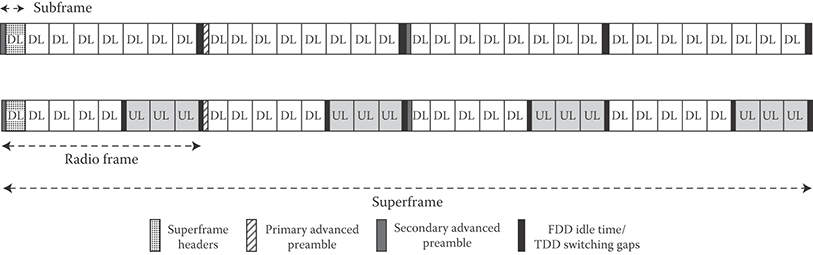
FIGURE 25.12 Structure of the IEEE 802.16m advanced preambles. (Adapted from Sassan Ahmadi, Mobile WiMAX; A Systems Approach to Understanding IEEE 802.16m Radio Access Technology, 1st Edition, Academic Press, 2010; IEEE 802.16m-08/0034r4, IEEE 802.16m System Description Document, (http://ieee802.org/16/tgm/index.html), December 2010.)
25.5.8 Multi-Antenna Techniques in IEEE 802.16m
25.5.8.1 Downlink MIMO Structure
IEEE 802.16m supports several advanced multiantenna techniques including single and MU-MIMO (spatial multiplexing and beamforming) as well as a number of transmit diversity schemes. In SU-MIMO scheme only one user can be scheduled over one (time, frequency, spatial) resource unit. In MU-MIMO, on the other hand, multiple users can be scheduled in one resource unit. Vertical encoding (or single codeword) utilizes one encoder block (or layer), whereas horizontal encoding (or multicodeword) uses multiple encoders (or multiple layers) in the transmit chain. A layer is defined as a coding and modulation input path to the MIMO encoder. A stream is defined as the output of the MIMO encoder that is further processed through the beamforming or the precoder block [6]. For spatial multiplexing, the rank is defined as the number of streams to be used for the user. Each SU-MIMO or MU-MIMO open-loop or closed-loop scheme is defined as a MIMO mode.
The DL MIMO transmitter structure is shown in Figure 25.13. The encoder block contains the channel encoder, interleaving, rate-matching, and modulating blocks per layer. The resource mapping block maps the complex-valued modulation symbols to the corresponding time–frequency resources. The MIMO encoder block maps the layers onto the streams, which are further processed through the precoder block. The precoder block maps the streams to antennas by generating the antenna-specific data symbols according to the selected MIMO mode. The OFDM symbol construction block maps antenna-specific data to the OFDM symbols. The feedback block contains feedback information such as CQI or CSI from the MS. Table 25.3 contains more information on various MIMO modes supported by the IEEE 802.16m.

FIGURE 25.13 Illustration of downlink/uplink MIMO structure. (Adapted from Sassan Ahmadi, Mobile WiMAX; A Systems Approach to Understanding IEEE 802.16m Radio Access Technology, 1st Edition, Academic Press, 2010; IEEE Std 802.16m-2011, IEEE Standard for Local and Metropolitan Area Networks—Part 16: Air Interface for Broadband Wireless Access Systems, Amendment 3: Advanced Air Interface, May 2011.)
TABLE 25.3 Downlink MIMO Modes
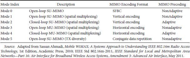
The minimum antenna configuration in the downlink and uplink is 2 × 2 and 1 × 2, respectively. For open-loop spatial multiplexing and closed-loop SU-MIMO, the number of streams is constrained to the minimum of number of transmit or receive antennas. For open-loop transmit diversity modes, the number of streams depends on the space-time coding schemes that are used by the MIMO encoder. The MU-MIMO can support up to two streams with two transmit antennas and up to four streams for four transmit antennas and up to eight streams for eight transmit antennas. Table 25.4 summarizes downlink MIMO parameters for various MIMO modes.
For SU-MIMO, vertical encoding is utilized, whereas for MU-MIMO horizontal encoding is employed at the BS. The stream to antenna mapping depends on the MIMO scheme that is used. CQI and rank feedback are transmitted to assist the BS in rank adaptation, mode switching, and rate adaptation. For spatial multiplexing, the rank is defined as the number of streams to be used for each user. In FDD and TDD systems, unitary codebook-based precoding is used for closed-loop SU-MIMO. An MS may feed back some information to the BS in closed-loop SU-MIMO such as rank, subband selection, CQI, PMI, and long-term CSI.
The MU-MIMO transmission with up to two streams per user is supported. The MU-MIMO schemes include two transmit antennas for up to two users, and four and eight transmit antennas for up to four users. Both unitary and nonunitary MU-MIMO schemes are supported. If the columns of the precoding matrix are orthogonal to each other, it is defined as unitary MU-MIMO. Otherwise, it is defined as nonunitary MU-MIMO [6]. Beamforming is enabled with this precoding mechanism. IEEE 802.16m has the capability to adapt between SU-MIMO and MU-MIMO in a predefined and flexible manner. Multi-BS MIMO techniques are also supported for improving sector and cell-edge throughput using multi-BS collaborative precoding, network coordinated beamforming, or intercell interference cancellation.
25.5.8.2 Uplink MIMO
The block diagram of uplink MIMO transmitter is illustrated in Figure 25.13. The BS assigns users to resource blocks and determines the modulation and coding scheme level and MIMO parameters (mode, rank, etc.). The supported antenna configurations include 1, 2, or 4 transmit antennas and >2 receive antennas. In the uplink, the MS measurements of the channel are based on downlink reference signals (e.g., common pilots or a midamble). The uplink MIMO modes and their parameters are contained in Tables 25.5 and 25.6.
TABLE 25.4 Downlink MIMO Parameters
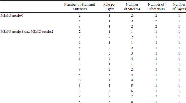
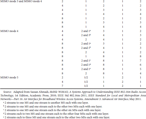
TABLE 25.5 Uplink MIMO Modes
Mode Index |
Description |
MIMO Encoding Format |
MIMO Precoding |
Mode 0 |
Open-loop SU-MIMO (transmit diversity) |
SFBC |
Nonadaptive |
Mode 1 |
Open-loop SU-MIMO (spatial multiplexing) |
Vertical encoding |
Nonadaptive |
Mode 2 |
Closed-loop SU-MIMO (spatial multiplexing) |
Vertical encoding |
Adaptive |
Mode 3 |
Open-loop collaborative spatial multiplexing (MU-MIMO) |
Vertical encoding |
Nonadaptive |
Mode 4 |
Closed-loop collaborative spatial multiplexing (MU-MIMO) |
Vertical encoding |
Adaptive |
Source: Adapted from Sassan Ahmadi, Mobile WiMAX; A Systems Approach to Understanding IEEE 802.16m Radio Access Technology, 1st Edition, Academic Press, 2010; IEEE Std 802.16m-2011, IEEE Standard for Local and Metropolitan Area Networks—Part 16: Air Interface for Broadband Wireless Access Systems, Amendment 3: Advanced Air Interface, May 2011.
TABLE 25.6 Uplink MIMO Parameters
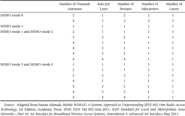
A number of antenna configurations and transmission rates are supported in uplink open-loop SU-MIMO including 2 and 4 transmit antennas with rate 1 (i.e., transmit diversity mode), 2 and 4 transmit antennas with rates 2, 3, and 4 (i.e., spatial multiplexing). The supported uplink transmit diversity modes include 2 and 4 transmit antenna schemes with rate 1 such as space frequency block coding (SFBC) and dual-stream precoder. The multiplexing modes supported for open-loop SU-MIMO include 2 and 4 transmit antenna rate 2 schemes with and without precoding, four transmit antenna rate 3 schemes with precoding, four transmit antenna rate 4 scheme. In FDD and TDD systems, unitary codebook-based precoding is supported. In this mode, an MS transmits a sounding reference signal in the uplink to assist the scheduling and precoder selection in the BS. The BS signals the resource allocation, MCS, rank, preferred precoder index, and packet size to the MS. The uplink MU-MIMO enables multiple MSs to be spatially multiplexed on the same radio resources. Both open-loop and closed-loop MU-MIMO are supported. The MSs with single transmit antenna can operate in open-loop SU-MIMO/MU-MIMO mode.
25.6 Overview of the IEEE 802.16m MAC Layer
There are various MAC functionalities and features that are specified by IEEE 802.16m standard some of which are extension of the existing features in the mobile WiMAX [8,7]. The following sections briefly describe selected MAC features.
25.6.1 MAC Addressing
IEEE 802.16m standard defines global and logical addresses for an MS that identify the user and its connections during a session. The MS is identified by the globally unique 48-bit IEEE extended unique identifier assigned by the IEEE Registration Authority [10,11]. The MS is further assigned the following logical identifiers: (1) An STID during network entry (or network reentry), which uniquely identifies the MS within the cell, and (2) an FID that uniquely identifies the control connections and transport connections with the MS. A temporary STID is used to protect the mapping between the actual STID during network entry. A deregistration identifier is defined to uniquely identify the MS within the set of paging group identifiers (PGID), paging cycle, and paging offset.
25.6.2 Network Entry
Network entry is the procedure through which an MS detects a cellular network and establishes a connection with that network. The network entry involves the following steps (see Figure 25.14):
Synchronization with the BS by acquiring the preambles
Acquiring necessary system information such as BS and NSP identifiers for initial network entry and cell selection
Initial ranging
Basic capability negotiation
Authentication/authorization and key exchange
Registration and service flow setup
Neighbor search is based on the same downlink signals as initial network search except for some information can be provided by the serving BS (i.e., neighbor advertisement messages). The BS responds to the MS initial ranging code transmission by broadcasting a status indication message in a predefined downlink frame/subframe.
25.6.3 Connection Management
A connection is defined as a mapping between the MAC layers of a BS and one (or several) MS. If there is a one-to-one mapping between one BS and one MS, the connection is called a unicast connection; otherwise, it is called a multicast or broadcast connection. Two types of connections are specified: control connections and transport connections. Control connections are used to carry MAC control messages. Transport connections are used to carry user data including upper-layer signaling messages. A MAC control message is never transferred over transport connection, and user data are never transferred over the control connections. One pair of bidirectional (DL/UL) unicast control connections are automatically established when an MS performs initial network entry. The user data communications are in the context of transport connections. A transport connection is unidirectional and established with a unique FID. Each transport connection is associated with an active service flow to provide various levels of QoS required by the service flow. The transport connection is established when the associated active service flow is admitted or activated, and released when the associated service flow becomes inactive. Transport connections can be preprovisioned or dynamically created. Preprovisioned connections are those established by system for an MS during the MS network entry. On the other hand, the BS or the MS can create new connections dynamically if required.
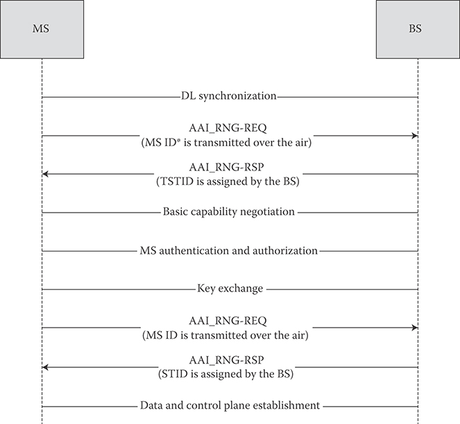
FIGURE 25.14 Network entry procedures. (Adapted from Sassan Ahmadi, Mobile WiMAX; A Systems Approach to Understanding IEEE 802.16m Radio Access Technology, 1st Edition, Academic Press, 2010; IEEE Std 802.16m-2011, IEEE Standard for Local and Metropolitan Area Networks—Part 16: Air Interface for Broadband Wireless Access Systems, Amendment 3: Advanced Air Interface, May 2011; IEEE 802.16m-08/0034r4, IEEE 802.16m System Description Document, (http://ieee802.org/16/tgm/index.html), December 2010.)
25.6.4 Quality of Service
IEEE 802.16m MAC assigns a unidirectional flow of packets with specific QoS requirements with a service flow. A service flow is mapped to a transport connection with an FID. The QoS parameter set is negotiated between the BS and the MS during the service flow setup/change procedure. The QoS parameters can be used to schedule traffic and allocate radio resource. The uplink traffic may be regulated based on the QoS parameters.
IEEE 802.16m supports adaptation of service flow QoS parameters. One or more sets of QoS parameters are defined for each service flow. The MS and BS negotiate the possible QoS parameter sets during service flow setup procedure. When QoS requirement/traffic characteristics for uplink traffic change, the BS may adapt the service flow QoS parameters such as grant/polling interval or grant size based on predefined rules. In addition, the MS may request the BS to switch the service flow QoS parameter set with explicit signaling. The BS then allocates resource according to the new service flow parameter set. In addition to the scheduling services supported by the legacy system, IEEE 802.16m provides a specific scheduling service and dedicated ranging channel to support real-time nonperiodical applications such as interactive gaming.
25.6.5 MAC Control Messages
To satisfy the latency requirements for network entry, HO, and state transitions, IEEE 802.16m supports fast and reliable transmission of MAC management messages. The transmission of unicast MAC management messages can be made more reliable using HARQ, where retransmissions can be triggered by an unsuccessful outcome from the HARQ entity in the transmitter. If MAC management message is fragmented into multiple MAC service data units, only unsuccessfully transmitted fragments are retransmitted.
25.6.6 MAC Headers
IEEE 802.16m specifies a number of efficient MAC headers for various applications comprising of fewer fields with shorter size compared to legacy standard generic MAC header [6,10,11]. The advanced generic MAC header consists of Extended Header Indicator, FID, and Payload Length fields. Other MAC header types include two-byte short-packet MAC header, which is defined to support small-payload applications such as VoIP which is characterized by small data packets and non-ARQ connection, Fragmentation extended header, Packing extended header for transport connections, MAC control extended header for control connections, and Multiplexing extended header that is used when data from multiple connections associated with the same security association (SA) are encapsulated in a single MAC protocol data unit. The structures of some MAC headers are shown in Figure 25.15.
25.6.7 ARQ and HARQ Functions
An ARQ block is generated from one or multiple MAC service data units or their fragments. ARQ blocks can be variable in size and are sequentially numbered. When both ARQ and HARQ are applied on a flow, HARQ and ARQ interactions are applied to the corresponding flow. If the HARQ entity in the transmitter determines that the HARQ process was terminated with an unsuccessful outcome, the HARQ entity in the transmitter informs the ARQ entity in the transmitter about the failure of the HARQ burst. The ARQ entity in the transmitter can then initiate retransmission and resegmentation of the appropriate ARQ blocks.
IEEE 802.16m uses adaptive asynchronous and nonadaptive synchronous HARQ schemes in the downlink and uplink, respectively. The HARQ operation is relying on an N-process (multichannel) stop-and-wait protocol. In adaptive asynchronous HARQ, the resource allocation and transmission format for the HARQ retransmissions may be different from the initial transmission. In the case of retransmission, control signaling is required to indicate the resource allocation and transmission format along with other HARQ necessary parameters. A nonadaptive synchronous HARQ scheme is used in the uplink where the parameters and the resource allocation for the retransmission are known in advance.
25.6.8 Mobility Management and HO
IEEE 802.16m supports both network-controlled and MS-assisted HO. The HO procedure may be initiated by either MS or BS; however, the final HO decision and target BS selection are made by the serving BS. The MS executes the HO command as instructed by the BS or cancels the procedure through HO cancellation message. The network reentry procedure with the target BS may be optimized, if the target BS obtains the MS context from the serving BS via core network. The MS may also maintain communication with serving BS while performing network reentry at target BS as directed by serving BS. Figure 25.16 illustrates the HO procedure.
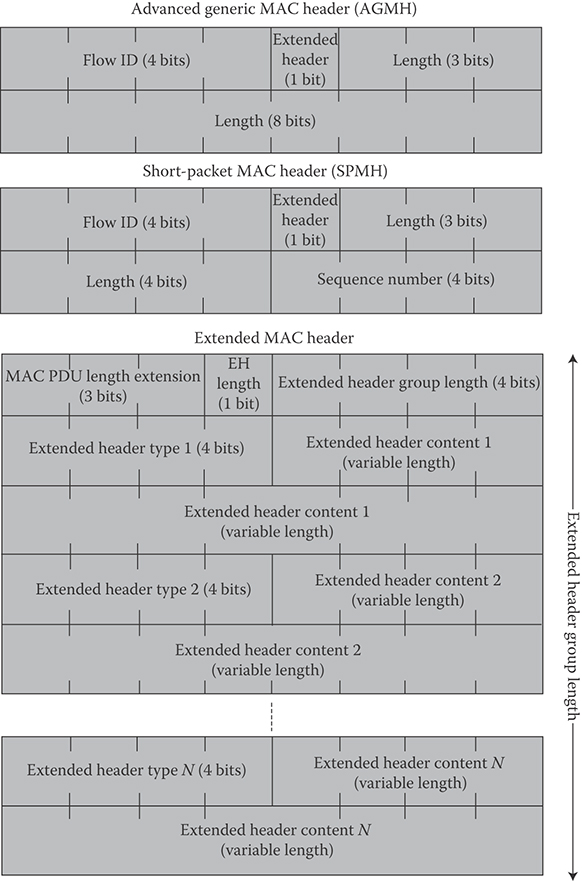
FIGURE 25.15 Structure of the IEEE 802.16m MAC headers. (Adapted from Sassan Ahmadi, Mobile WiMAX; A Systems Approach to Understanding IEEE 802.16m Radio Access Technology, 1st Edition, Academic Press, 2010; IEEE Std 802.16m-2011, IEEE Standard for Local and Metropolitan Area Networks—Part 16: Air Interface for Broadband Wireless Access Systems, Amendment 3: Advanced Air Interface, May 2011; IEEE 802.16m-08/0034r4, IEEE 802.16m System Description Document, (http://ieee802.org/16/tgm/index.html), December 2010.)
The HO procedure is divided into three stages (1) HO initialization, (2) HO preparation, and (3) HO execution. Upon completion of HO execution, the MS is ready to perform network reentry with the target BS. In addition, HO cancellation procedure is defined to allow an MS to cancel an HO procedure [6,10].
The HO preparation is completed when the serving BS informs the MS of its HO decision via an HO control command. The signaling may include dedicated ranging resource allocation and resource preallocations for MS at target BS for optimized network reentry. The control signaling includes an action time for the MS to start network reentry at the target BS and an indication of whether MS should maintain communication with serving BS during network reentry. If the data-plane cannot be maintained between MS and the serving BS during network reentry, the serving BS stops allocating resources to MS for transmission during action time. If the MS is instructed by the serving BS via HO control command, the MS performs network reentry with the target BS during action time while communicating with the serving BS. However, the MS stops communication with the serving BS after completion of the network reentry with target BS. In addition, the MS cannot exchange data with the target BS prior to the completion of network reentry.
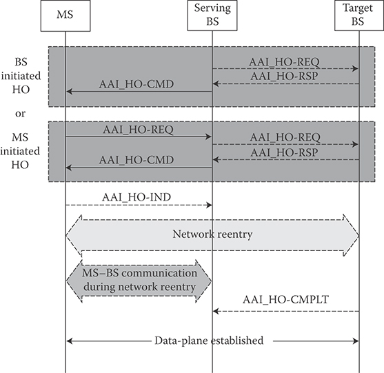
FIGURE 25.16 IEEE 802.16m HO procedure. (Adapted from Sassan Ahmadi, Mobile WiMAX; A Systems Approach to Understanding IEEE 802.16m Radio Access Technology, 1st Edition, Academic Press, 2010; IEEE Std 802.16m-2011, IEEE Standard for Local and Metropolitan Area Networks—Part 16: Air Interface for Broadband Wireless Access Systems, Amendment 3: Advanced Air Interface, May 2011.)
25.6.9 Power Management
IEEE 802.16m provides power management functions including sleep mode and idle mode to lower power consumption of the MSs. Sleep mode is a state in which an MS performs prenegotiated periods of absence from the serving BS. The sleep mode may be enacted when an MS is in the connected state. Using the sleep mode, the MS is provided with a series of alternative listening and sleep windows. The listening window is the time interval in which MS is available for transmit/receive of control signaling and data. The IEEE 802.16m has the capability of dynamically adjusting the duration of sleep and listening windows within a sleep cycle based on changing traffic patterns and HARQ operations. When an MS is in the active mode, sleep parameters are negotiated between the MS and BS. The BS instructs the MS to enter sleep mode. MAC control messages can be used for sleep mode request/response [6,10,11]. The period of the sleep cycle is measured in units of frames or superframes and is the sum of sleep and listening windows. During the MS listening window, the BS may transmit the traffic indication message intended for one or multiple MSs. The listening window can be extended through explicit/implicit signaling. The maximum length of the extension is to the end of the current sleep cycle [6,10].
Idle mode allows the MS to become periodically available for downlink broadcast traffic messaging such as paging message without registration with the network. The network assigns MSs in the idle mode to a paging group during idle mode entry or location update. The MS monitors the paging message during paging-available interval. The start of the paging-available interval is calculated based on paging cycle and paging offset. The paging offset and paging cycle are defined in terms of number of superframes. The serving BS transmits the list of PGID at the predetermined location at the beginning of the paging available interval. An MS may be assigned to one or more paging groups. If an MS is assigned to multiple paging groups, it may also be assigned multiple paging offsets within a paging cycle where each paging offset corresponds to a separate paging group. The MS is not required to perform location update when it moves within its assigned paging groups. The assignment of multiple paging offsets to an MS allows monitoring paging message at different paging offsets when the MS is located in one of these paging groups. When an MS is assigned to >1 paging group, one of the paging groups is called Primary Paging Group and others are known as Secondary Paging Groups. If an MS is assigned to one paging group, that paging group is considered the Primary Paging Group. When different paging offsets are assigned to an MS, the Primary Paging Offset is shorter than the Secondary Paging Offsets. The distance between two adjacent paging offsets should be long enough so that the MS paged in the first paging offset can inform the network before the next paging offset in the same paging cycle so that the network avoids unnecessary paging of the MS in the next paging offset. An MS, while in paging available interval, wakes up at its primary paging offset and looks for primary PGID information. If the MS does not detect the primary PGID, it will wake up during its secondary paging offset in the same paging cycle. If the MS can find neither primary nor secondary PGIDs, it will perform a location update. The paging message contains identification of the MSs to be notified of pending traffic or location update. The MS determines the start of the paging listening interval based on the paging cycle and paging offset. During paging available interval, the MS monitors the superframe header and if there is an indication of any change in system configuration information, the MS will acquire the latest system information at the next instance of superframe header transmission. To provide location privacy, the paging controller may assign temporary identifiers to uniquely identify the MSs in the idle mode in a particular paging group. The temporary identifiers remain valid as long as the MS stays in the same paging group.
An MS in idle mode performs location update, if either of these conditions is met: paging group location update, timer based location update, or power down location update. The MS performs location update when it detects a change in the paging group. The MS detects the change of paging group by monitoring the PGIDs, which are periodically transmitted by the BS. The MS periodically performs location update procedure prior to the expiration of idle mode timer. At every location update including paging group update, the idle mode timer is reset.
25.6.10 Security
Security functions provide subscribers with privacy, authentication, and confidentiality across IEEE 802.16m network. The MAC packet data units are encrypted over the connections between the MS and BS. Figure 25.17 shows the breakdown of IEEE 802.16m security architecture.
The security architecture is divided into security management, encryption and integrity logical entities. The security management functions include overall security management and control, Extensible Authentication Protocol encapsulation/de-encapsulation, privacy key management (PKM) control, SA management, and identity/location privacy. The encryption and integrity protection functions include user data encryption and authentication, management message authentication, message confidentiality protection [6,10]. Authorization is a process where BS and MS mutually authenticate the identity of each other. Authentication is performed during initial network entry after security capabilities and policies are negotiated. The basic MS capability negotiation is performed prior to authentication and authorization. Reauthentication is performed before the authentication credentials expire. Data transmission may continue during reauthentication process. In the legacy system there is no explicit means by which the identity of a user is protected. During initial ranging and certificate exchange, MS MAC address is transmitted over the air, revealing user identity or user location information that may result in compromising the security aspects of the system. IEEE 802.16m incorporates mechanisms such a pseudo-identity to mitigate this problem. IEEE 802.16m inherits the key hierarchies of the legacy system. The IEEE 802.16m uses the PKMv3 protocol to transparently exchange authentication and authorization messages. The PKM protocol provides mutual and unilateral authentication and establishes confidentiality between the MS and the BS. Some IEEE 802.16m keys are derived and updated by both BS and MS. The key exchange procedure is controlled by the security key state machine, which defines the allowed operations in the specific states. The key exchange state machine is similar to that of the legacy system.
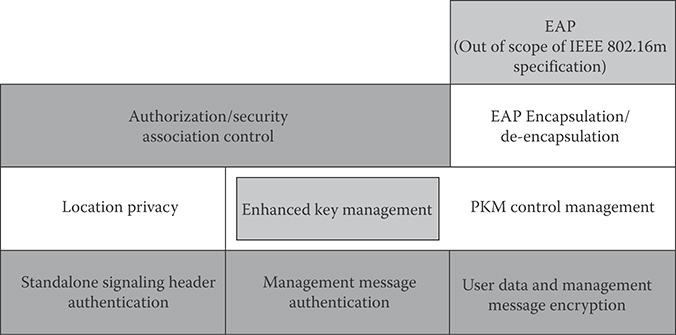
FIGURE 25.17 Functional blocks of IEEE 802.16m security architecture. (Adapted from Sassan Ahmadi, Mobile WiMAX; A Systems Approach to Understanding IEEE 802.16m Radio Access Technology, 1st Edition, Academic Press, 2010; IEEE Std 802.16m-2011, IEEE Standard for Local and Metropolitan Area Networks—Part 16: Air Interface for Broadband Wireless Access Systems, Amendment 3: Advanced Air Interface, May 2011.)
A SA is the set of information required for secure communication between BS and MS. However, the SA is not equally applied to messages within the same flow. According to the value of MAC header fields, the SA is selectively applied to the control connections. When a service flow is established between the BS and the group of MSs, it is considered as multicast and it is serviced by a group SA. The MS and the BS may support encryption methods and algorithms for secure transmission of MAC packet data units. Advanced encryption standard is the only cryptographic method supported in IEEE 802.16m [6,10]. The legacy system does not define confidentiality protection for control-plane signaling. IEEE 802.16m selectively protects the confidentiality of control-plane signaling. The use of MAC message authentication code in legacy systems only proves the originator of messages and ensures integrity of the messages. IEEE 802.16m supports the selective confidentiality protection over MAC control messages. If the selective confidentiality protection is activated, the negotiated keying materials and cipher suites are used to encrypt the management messages. Integrity protection is applied to standalone MAC signaling header.
References
1. Recommendation ITU-R M.1645, Framework and overall objectives of the future development of IMT-2000 and systems beyond IMT-2000, June 2003.
2. Report ITU-R M.2134, Requirements related to technical system performance for IMT-Advanced radio interface(s), November 2008.
3. IEEE 802.16m-07/002r10, IEEE 802.16m System Requirements, (http://ieee802.org/16/tgm/index.html), January 2010.
4. Report ITU-R M.2135-1, Guidelines for evaluation of radio interface technologies for IMT-Advanced, December 2009.
5. IEEE 802.16m-08/004r5, IEEE 802.16m Evaluation Methodology Document, (http://ieee802.org/16/tgm/index.html), January 2009.
6. Sassan Ahmadi, Mobile WiMAX; A Systems Approach to Understanding IEEE 802.16m Radio Access Technology, 1st Edition, Academic Press, 2010.
7. WiMAX Forum Network Architecture Release 1.5 Version 1—Stage 2: Architecture Tenets, Reference Model and Reference Points, http://www.wimaxforum.org/resources/documents/technical/release, September 2009.
8. WiMAX Forum Mobile System Profile, Release 1.5, September 2010 (http://www.wimaxforum.org/resources/documents/technical/release)
9. IEEE 802.16m-08/0034r4, IEEE 802.16m System Description Document, (http://ieee802.org/16/tgm/index.html), December 2010.
10. IEEE Std 802.16m-2011, IEEE Standard for Local and Metropolitan Area Networks—Part 16: Air Interface for Broadband Wireless Access Systems, Amendment 3: Advanced Air Interface, May 2011.
11. IEEE Std 802.16-2009, IEEE Standard for Local and Metropolitan Area Networks, PART 16: Air Interface for Broadband Wireless Access Systems, May 2009.