
36
IP Multimedia Subsystem: Analysis of Scalability and Integration*
Lava N. Al-Doski, Rabindra Ghimire and Seshadri Mohan
36.3 Scalability Analysis of IMS
Impact of CDMA2000–WLAN Integration
36.1 Introduction
IP multimedia subsystem (IMS) is an architectural framework for delivering multimedia services standardized by the Third-Generation Partnership (3GPP/3GPP2) in late 1999. IMS enables multimedia and voice services to be delivered in a well-structured manner. It facilitates services integration over disparate networks, including the Internet and cellular networks. IMS enables advanced services such as email, video conference, presence, chat, push to talk (PTT), and IPTV to become widely available to the users.
The services infrastructure has traditionally evolved in a “stove-piped” manner as shown in Figure 36.1a, where services are established, maintained, and terminated independently of each other. A number of functions common to many services such as billing, quality of service (QoS), and user profile are developed and maintained specifically for each service, thereby increasing the cost of development and maintenance as well as decreasing the utilization of resources. The stove piped arrangement is unsuitable because of its inability to share common functions and in view of the tremendous demand for new types of services together with the exponential increase in the number of users.
The IMS system is organized as a layered architecture where functions are built on top of each other in a horizontal manner as illustrated in Figure 36.1b. When structured in this manner, the system allows multiple services to share a common set of functions without the need to redevelop each function separately for each service. This concept of reuse of functions and/or capabilities will pave the way for rapid service development and eliminate redundant development efforts associated with every new service development.
*This chapter is reproduced in part or full from References 18 and 19, © IEEE, permission for which has been received from IEEE.
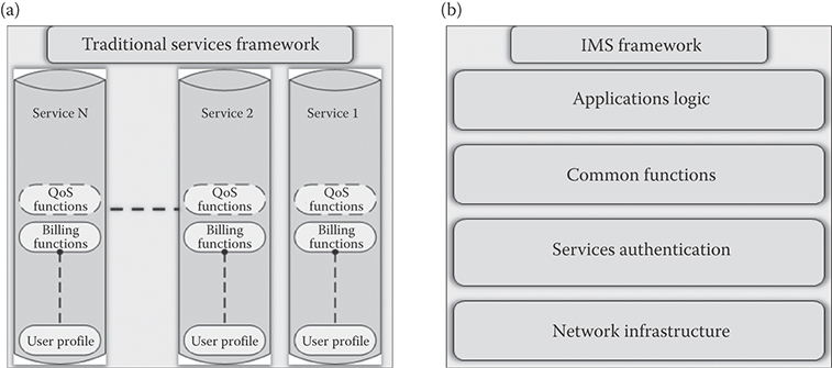
FIGURE 36.1 (a) Traditional service framework and (b) IMS framework.
IMS is access and device independent. It can be integrated with 3G and 4G networks regardless of the network technology (WLAN, LTE, WiMax, etc.). The user can use IMS services regardless of the device used. IMS is capable of delivering services with QoS to the user. It facilitates rapid service development, and has the potential to offer a rich suite of applications to the users. This approach encourages service providers to establish a service creation platform open to third-party vendors. In addition to 3GPP, other standardization bodies have embraced IMS protocol developments which are based on the IETF-defined session control [1]. A complementary effort by Open Mobile Alliance (OMA) [2] is aimed at stimulating the creation and adoption of new enhanced mobile services such as video, entertainment, and information services. The alliance works toward standardization and interoperability of all application-related issues.
After an introduction to IMS in Section 36.2 with an overview of the architecture, the protocol suite, and the control structures, Sections 36.3 provides an analysis of the impact of introducing services and integrating IMS with CDMA/WLAN hybrid networks. Section 36.4 provides a summary of the insights from the analysis of Section 36.3.
36.2 IP Multimedia Subsystem
Service providers anticipate that IMS will benefit the end users by
Facilitating delivery of services with QoS to the end user
Enabling an environment for the development of new and advanced blended services
Ensuring secure transactions of user information
Facilitating the collection of all services utilized by a user that can be supplied to the billing systems to create an integrated bill
Facilitating the delivery of services over disparate networks
Facilitating ease of use of services by allowing users to create a single profile and register once for all the services
Figure 36.2 illustrates the relationship between the IMS layer, different types of wireless and wireline networks such as WiFi, universal mobile telecommunications system (UMTS), long-term evolution (LTE), and the public switched telephone network (PSTN), and the application layer.
The IMS layer provides many common services, including registration, authentication, user data provisioning, session negotiations, and data collection for billing and charging purposes. This layer includes IMS entities such as call session control functions (CSCFs) and home subscriber server (HSS).
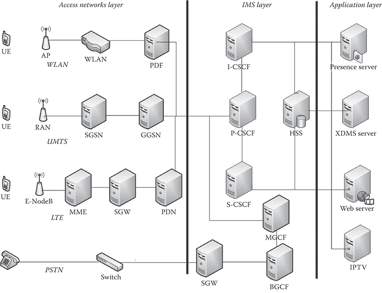
FIGURE 36.2 IMS architecture.
The application layer includes all the application servers that offer a variety of services and applications to the end user. Most of these application servers utilize the session initiation protocol (SIP) as the signaling protocol for services negotiation.
In a typical service scenario, a user requests a service via an access network. The request is subsequently transferred from the access network to the IMS subsystem, where the request is processed and then forwarded to the application layer. Figure 36.1 shows some example applications such as presence, Parlay X, and IPTV.
IMS's core network server is a CSCF server. This function takes on four different variations, which are proxy, serving, interrogating, and emergency call session control functions, abbreviated as P-CSCF, S-CSCF, I-CSCF, and E-CSCF, respectively. The serving CSCF is considered to be the brain of IMS. Each server performs different tasks to ensure service delivery to the user.
36.2.1 IMS Control Functions
The P-CSCF, being located in the visitor's network, serves as the first point of contact for the user. Subsequently, the user's requests are processed by I-CSCF and then P-CSCF. In order to access the IMS system, users need to have at least one address of the IMS system. In the 3GPP design, users need to perform P-CSCF discovery mechanism. P-CSCF carries out several tasks as highlighted below [3]:
During a registration request, P-CSCF will review the request and then reroute it to the appropriate I-CSCF based on the user's home location.
After acquiring the address of S-CSCF during the registration process, P-CSCF is responsible for rerouting SIP packets to S-CSCF.
P-CSCF is responsible for maintaining a secure connection with the user.
It composes and decomposes SIP messages.
It manages emergency calls and forward them to the E-CSCF server [1].
It generates charging information and forward it to the charging entity.
It updates the SIP packets with the network information.
In some cases, it hides the network topology.
The I-CSCF, which is located in the home network, can access the IMS system data base HSS. The following list highlights the tasks performed by I-CSCF:
It is responsible for retrieving the S-CSCF address from HSS and rerouting SIP packets to S-CSCF
It is responsible for rerouting packets to a different IMS network.
It is responsible for receiving and rerouting SIP messages arriving from a different IMS system.
The S-CSC is considered the most important server that is located in the home network and that maintains access to HSS. S-CSCF carries out major tasks within the IMS system as highlighted below:
Authorizing and authenticating users during registration
Serving as an SIP registrar, accessing HSS using the diameter protocol, and providing HSS with the user information to ensure secure sessions
Checking SIP messages to determine if an application server is needed and filtering the messages using trigger points, and forwarding the message to the correct application server
Managing and terminating sessions as necessary [4] and handling user requests for registration and downloading user profile from HSS
Collecting charging information for services utilized by the users and proving the information to the charging unit
Deregistering users when required
Routing SIP messages to IMS systems in different domains
The E-CSCF server has been added recently by 3GPP standardization and Federal Communications Commission (FCC) to provide emergency access to users. The server's task is to overview emergency calls. On receiving an emergency call, it retrieves user location and information through dedicated location servers and then forward the location of the user to the appropriate emergency dispatcher service. E-CSCF provides an essential delay-sensitive service to the user [1].
The HSS serves as the main database of the IMS system by maintaining profiles of users with information to identify, register, authenticate, and authorize users so as to enable the users to avail the rich multimedia services enabled by IMS. There might be more than one HSS so that the system can scale with increasing subscribers. HSS keeps the subscription information of the user by applying a criterion known as initial filter criteria (iFC), which are logical filters that contain trigger points that get downloaded to S-CSCF when the user registers.
Application servers represent the end point that process requests for services initiated by the user. IMS has multiple servers assigned to perform various services. Most of these servers have built-in SIP proxies [5]. To ensure that every user is served by the requested services, the HSS will choose the right application server based on the user-requested services and the applicable policies. Application servers are considered as some of the most essential entities as they facilitate the use of a rich set of services by the user. Service providers are deploying what is referred to as service-oriented architectures (SOA) to provide integrated services to end users. SOA is capable of supporting third-party applications [3].
Media resource function (MRF) is a node responsible for media control in the home network. It is divided into two functions, media resource function controller (MFRC) and media resource function processor (MRFP). MRFC performs media control such as sending announcements and transcoding of media whereas MRFP processes MRFC instructions, media streaming by multiple parties, and codec media information. An H.248 interface [6] facilitates media capability negotiation between the nodes requesting the establishment of a session.
Breakout gateway control function (BGCF) is responsible for routing SIP messages to a circuit switching network; it uses telephone numbers to route calls to the PSTN.
36.2.2 IMS Protocol Suite
Within the IMS system, a number of protocols play an important role in facilitating the IMS system to successfully deliver services to the end user. Some significant ones are briefly described below.
Session initiation protocol (SIP) SIP is an application layer protocol created by IETF (Internet Engineering Task Force). SIP is one of the most essential protocols for multimedia session management that is used to create, maintain, and terminate sessions. SIP is responsible for the session management of services such as video conference, voice over IP (VoIP), chat, and multimedia streaming. For this reason, SIP was adopted by 3GPP as the signaling protocol for session management. Media stream is transported using the real-time transport protocol (RTP) [7].
Session description protocol (SDP) The SDP created by IETF defines the format of the SIP messages. SIP defines the type of information being sent, while SDP represents the format of these messages.
Real-time transport protocol (RTP) The RTP protocol introduced by IETF defines the formats of the media packets to be delivered. It is used to deliver multimedia steams in services such as VoIP, video conference, and other IMS applications.
Diameter protocol The diameter protocol designed by IETF is an authorization, authentication, and accounting (AAA) protocol, and is a successor to the RADUIS protocol. The diameter protocol is chosen to manage the delivery of IMS client information between I-CSCF, S-CSCF, and HSS.
SIP being the most important of the protocols within the IMS suite of protocols, a brief description of the protocol is provided below.
36.2.3 SIP Architecture
To keep track of the users and the session, SIP requires all the users to register before establishing a session. SIP entities include the following:
User agent client (UAC) is the entity that requests a session or service. Prior to requesting service, the SIP client needs to register (see Figure 36.3).
User agent server (UAS) is the entity that receives and responds to the service request initiated by UAC. A SIP server can be another user's agent.
SIP proxy is the entity that reroutes SIP messages. This capability facilitates SIP messages to be routed to the final destination by multiple SIP proxies. Unlike the “best-effort” IP routing, SIP message requests and responses should follow the same routing hops to keep track of the session state. However, that is not the situation with RTP packets that carry media stream. The media stream in either direction follows the best-effort IP routing scheme.
SIP registrar: Each UAC needs to register with the service. The registration request is processed by the SIP registrar server, which keeps track of user registrations. The SIP registrar is usually integrated with the SIP proxy.
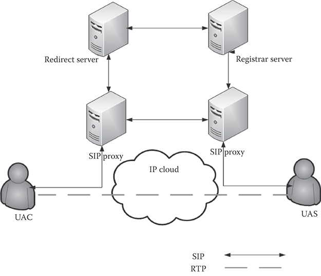
FIGURE 36.3 SIP architecture.
36.2.4 SIP Methods
As shown in Figure 36.4 [7], SIP messages are described using SDP. The first part of the message is the message header which represents the purpose of the message indicated by the SIP method type, the initiating and receiving address information, and the sequence of the message. The second part of the message (separated by space) represents information about the media such as encoding and decoding information (codec specifications), device information, a line indicating the SIP method, together with the main purpose of the SIP message and the address which initiated the request.

FIGURE 36.4 SIP INVITE.
TABLE 36.1 SIP Methods
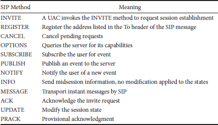
Besides the INVITE method, SIP deploys various other methods while communicating with nodes. SIP messages or methods [1] are sent and received within the SIP packets. Table 36.1 lists the SIP methods.
36.2.5 User Identification in IMS
The IMS system uses different kinds of identities to identify the user within the system; each has its own purpose. The users’ IDs may be public or private.
IMS users’ public user identities are used as a contact address or a business card and it is used by IMS to route SIP messages to other users. Public user identity comes in the format of SIP URL ([email protected] or [email protected]) or as a TEL URL (+000-00-0000). Users may have multiple public user identities.
Each IMS user may be assigned one or more private user identities. This identity is used internally by IMS to identify user information while registering or authenticating. Users are normally not aware of this address, which is in the format of network access identifier ([email protected]). Both private and public identities are stored in HSS.
36.2.6 IMS Services
IMS provides powerful session and service management. The following list highlights the most common services:
Presence service provides information concerning the status and availability of the users. This service, which updates users’ presence information dynamically in real time, makes communications among users more convenient. User information may include [3]
Availability
User device capabilities
User location
Current activity
Communication preferences
Presence servers are part of the IMS application layer. IMS users subscribe with their presence information “presentities” to resources list (user contact list). Users who request the resources list are called “Watchers.” The IMS user updates “publish” their “presentities” to the resources list to be watched by others.
Conferencing facilitates session establishment between two or more users due to powerful session management mechanism.
Push to talk enhances a user's experience with a Walki Talki-like service by allowing users to push a terminal button and speak with another user without the need to dial. PTT server is also associated with XDMS server.
Instant message enables users to send IM messages through the IMS system. IMS has two modes for sending IM. The first mode is session based, and the second is pager based.
36.2.7 Quality of Service
Service providers are required to provide a certain level of service performance for the users depending on the service level subscription. Service providers reserve resource to ensure service delivery with QoS. In IMS, different priorities may be assigned to different services, as some services are less delay tolerant than others. QoS is impacted upon by the following factors [8,9]:
Delay and jitter
Cost
Bit error rate
Likelihood of failure
Throughput
QoS is a key metric that may be related to the user experience. QoS may be enforced using the differentiated services or Diffserv technique defined by IETF [10] and adopted by 3GPP for use by IMS. Diffserv follows the idea of differentiating packet flows into 3GPP QoS classes shown in Table 36.2.
36.2.8 IMS Procedures
36.2.8.1 P-CSCF Discovery
Before using IMS services, users need a starting point to reach and interact with the IMS system to perform registration and authentication. Since P-CSCF is the first and only contact with users, UACs obtain the address of P-CSCF by a discovery process. Two standards are used for proxy discovery; the first one is by using the dynamic host configuration protocol (DHCP), and the second by the discovery process used in GPRS. In the DHCP procedure, the user sends a query to the DHCP server, the server queries the domain name system (DNS) server and forward the proxy address to the user [3]. In the GPRS discovery process, users request P-CSCF address in the PDP context activation request. The gateway GPRS support node (GGSN) processes the request and sends the proxy address to the user.
36.2.8.2 IMS Registration
IMS users need to perform the registration procedure with the system before establishing any service. The registration procedure in general establishes a connection with the user, loads the user's profile, authenticates the user and allocates resources, and establishes security agreements. During registration, IMS terminals register their public user identities with the home network. Usually, the P-CSCF, which is located in the visitor network, ensures that capabilities and roaming agreements are available to contact the home network. The user starts the registration by sending an SIP registration request [4]. The registration process is illustrated in Figure 36.5.
TABLE 36.2 3GPP QoS Classes
Class Type |
Service Example |
Conversational class |
Voice |
Streaming class |
Video conference |
Interactive class |
Web browsing |
Background class |
The user initiates the SIP method REGISTER; P-CSCF, being located in the visitor's network, will perform DNS query for the URI of I-CSCF. When forwarding the REGISTER method, the proxy inserts its address to make sure it receives back SIP methods to its own address.
The I-CSCF serves as a router and a load balancer. The I-CSCF will look into the REGISTER message and extract the user public and private identities and network ID and then send diameter protocol user-authentication request (UAR) to the HSS [11].
The HSS examines the received information, and verifies that roaming agreements are in place in case a visitor network ID is received.
The HSS authenticates the user and assigns the appropriate S-CSCF to the user, then forward them in its response diameter user-authentication answer (UAA).
The I-CSCF receives the UAA and extracts the S-CSCF address and then forward the SIP REGISTER to the S-CSCF.
The S-CSCF receives the REGISTER request and sends the multimedia authorization answer (MAA).
Upon receiving the MAA message, the HSS saves the S-CSCF URI. The HSS sends MAA back to the S-CSCF which contains authentication information of the user.
As part of the security system, IMS users are required to accept a challenge. Basically, the IMS proposes a challenge for the user as a form of protecting the system from flooding with fake users’ request.
The user will send a registration request again with the challenge reply which gets processed as before.
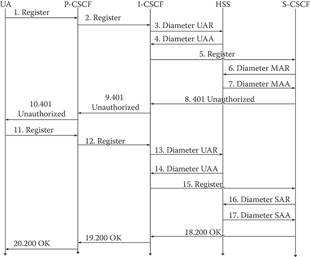
FIGURE 36.5 IMS user registration procedure.
In the second attempt, the I-CSCF will send the registration information to the HSS in the form of UAR.
The HSS sends back UAA which includes the address of the S-CSCF allocated to the user.
The I-CSCF sends the REGISTER to the S-CSCF with the user information.
The S-CSCF receives the user information and sends the SAR diameter message to notify the HSS that the user is registered and authenticated.
The HSS receives SAR diameter message and sends the user profile, user public identity, and the iFC to indicate the application server with which the user will be connected.
The S-CSCF sends 200 OK to indicate the registration procedure was successful.
36.3 Scalability Analysis of IMS
36.3.1 Impact of Service Usage
The goal of IMS is to bring forth the flexibility and power of the Internet to 3G cellular systems and to evolve cellular networks along their path toward and beyond 3G. Among the services facilitated by IMS are video conferencing, chat, instant messaging, PTT. The SIP, whose purpose is to handle sessions, forms a major protocol of the IMS standard. SIP facilitates the establishment, modification, and termination of sessions in IMS. The IMS system is designed to have registration areas. Registration areas constitute a number of cells. Whenever a user arrives at a registration area, the user terminal initiates a registration request. The analysis shows the rate of queries/updates to IMS servers, which are triggered as a result of a user's request for a service or due to users moving into a new registration area. The analysis assumes several parameters of a 3G system such as the density of the 3G terminals, total number of cells per registration area, average speed of a terminal, and the average rate at which each service is initiated by a terminal. The analysis incorporates mobility models to ensure realistic performance analysis. The analysis utilizes the fluid flow model which has been applied to ANSI-41 and GSM systems [12,13]. The analysis utilizes gamma and uniform distributions for the residence time of a user in a registration area to determine the registration rate. The analysis examines the effects of the gamma distribution for the residence time by varying gamma's parameters (shape parameter and the scale parameters). In order to conduct the analysis, the following assumptions are made, some of which are taken from earlier papers (see Reference 13). According to the fluid flow mobility model, the rate of registration, R, is given by
where ρ is the terminal density per unit area, v the velocity of the terminal km/h, and L the length of the perimeter length of the region (km).
Assumptions:
Total number of registration areas = 226
Registration area size = 60 km2
L = 30. 984 km
Speed v = 6 km/h
Mean density = 48 IMS terminals/km2
Average IM rate = 2/h/terminal
Average chat rate = 1.5/hr/terminal
Average PTT rate = 3/h/terminal
Average number of video conferences = 1/h/terminal
As an example of sizing calculations, the above equation can be applied to calculate registration rate initiated by users following the fluid flow model. Each registration request then initiates a signaling flow using which one can calculate the rate of queries/updates to each IMS server due to user mobility leading to registration requests. Using the service mix assumptions stated above, and the signaling flow for each service, rate of queries/updates to each server can be calculated. The signaling flows due to registration as well as other services are not shown here due to space limitations (see Reference 3 for further details). Figure 36.6a shows the number of hits while requesting registration. Figure 36.6b shows the number of queries to the IMS servers while using services mix consisting of instant messaging, PTT, chat, and video conferencing for both the originating and the terminating ends.
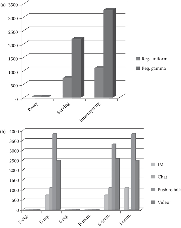
FIGURE 36.6 (a) The registration rate on the IMS servers when using two kinds of distributions for the residence time of the users. (b) Queries to originating and terminating IMS servers while using various services.
36.3.2 Impact of CDMA2000–WLAN Integration
This analysis shows the impact of delivering 3G services to user terminals over hybrid WLAN/CDMA2000 networks. Such hybrid networks have multifaceted objectives: offer improved 3G multimedia services to users, increase the reliability of the system, and enhance in-building coverage thereby facilitating service providers to extend wireless services to enterprises. The hybrid network will also facilitate terminals to access different networks to obtain the needed services without being obligated to have different billing information or different accounts. The IMS service infrastructure will facilitate service delivery transparently over the hybrid CDMA2000 and WLAN network to different types of terminals, thereby providing transparency of service delivery to networks and terminal types. Besides its applicability to 3G networks, IMS is also being considered by researchers as part of the 4G family due to its advanced features and the number of disparate services that can be provided such as PTT, video conferencing, presence, and web services to the user. In designing a service infrastructure for either 3G or 4G networks, IMS components are distributed according to their functions into the integrated design as part of the service and application layer. To mimic user movement, the analysis considers mobility models. The analysis carried out is intended to help network designers and architects of 3G and 4G networks with insights into the signaling load generated by IMS due to user mobility and the frequency of invocation of services as well as into ways to distribute the load and scale network design.
36.3.2.1 CDMA2000 and WLAN Interworking
We analyze the deployment of IMS within the CDMA2000/WLAN hybrid network. The integration between different networks will facilitate the development of new services that can be attractive to the users. The users will also have different networks to connect to depending on their location. Expanding this idea can serve well for the 3G and beyond services development [14]. The hybrid network structure provides WLAN users with IMS services, which will require the integration of WLAN with a service provider's CDMA2000 network. The interworking of WLAN within CDMA2000 will provide a view of the user benefits of having hybrid networks. The scheme is adapted from Reference 15. In this scheme, WLANs serve as the access provider network and CDMA2000 network serves as the backbone network, where the IMS main core belongs. The authors in Reference 16 proposed two interworking schemes, tightly coupled interworking and loosely coupled interworking. Loosely coupled integration is a more flexible scheme in comparison with the tightly coupled integration. The tightly coupled integration requires that either or both networks belong to the same service provider or, in the case of multiple service providers, it requires having certain physical interfaces between the networks. In loosely coupled integration, the WLAN gateway is connected to the packet control function (PCF) through the Internet. The PCF views the WLAN network as another 3G network and reroutes the packets to the packet data serving node (PDSN), which, in turn, routes the packets to the home network. Here, PDSN acts as the connection point between the radio access and IP network.
36.3.2.2 IMS Integration
Figure 36.7 shows the overall design of the system. Since P-CSCF is the first contact with the user, the P-CSCF is integrated with PCF. The HSS is integrated with home-AAA (H-AAA) to provide access to the user profile for updates and authentication purposes. The entities S,I-CSCF are integrated with home agent (HA) to facilitate access to the HSS and to ensure accessibility by I-CSCF to other 3G networks. CDMA2000 supports mobile IP [17], which requires that all visitor networks contain the foreign agent (FA) and the foreign-authentication authorization accounting (F-AAA) servers while the home networks contain the HA and the H-AAA server.
36.3.2.3 Scenarios
The CDMA2000 network consists of registration areas (shown hexagonal in shape). It is assumed that these areas have a uniform size and they contain WLAN networks (hot spots) such as airport, university, libraries, and so on, as shown in Figure 36.7. It is preferable for the mobile terminal to switch to the WLAN network in order to utilize the increased bandwidth available within the WLAN. Two scenarios are considered: in the first one, the mobile terminal moves from CDMA2000 to WLAN network. The second complementary scenario assumes that a mobile terminal also roams in the WLAN network while using IMS services.
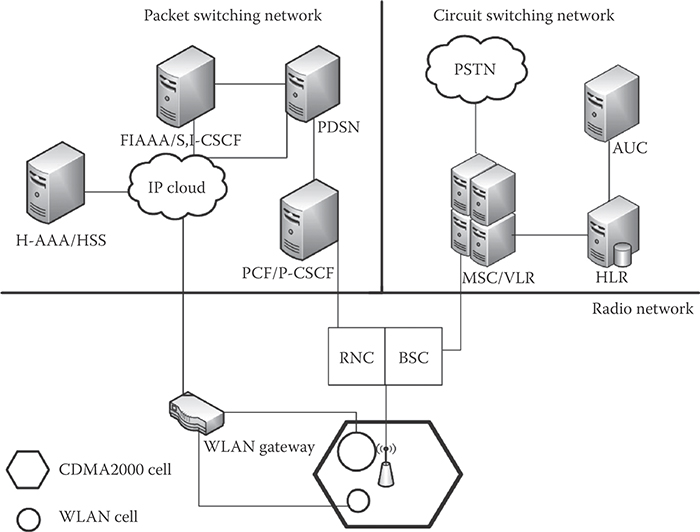
FIGURE 36.7 Hybrid network architecture.
The mobile terminal may roam from the WLAN network back to the CDMA2000 network. In order to capture the services offered by the system, it is assumed that, in both scenarios, the mobile terminal utilizes IMS services while moving from one network to the other. It is also suggested in both scenarios that a user will automatically switch to the WLAN network as soon as that user enters the WLAN network. In order to ensure service continuity, a mobile terminal needs to register while moving to a new network. The registration should take place within the access network and the IMS service plane itself. To examine the design complexity of such a system, user mobility should be modeled appropriately. The CDMA2000 network users’ movement is considered to be of faster pace compared to the WLAN users, the movement of which is modeled by fluid flow mobility model. Users within WLAN network tend to move slower and exercise more random movements in comparison with CDMA2000 network users, for which the random walk mobility model is suitable. The following section further explains the two mobility models. The analysis is illustrated via an example, which requires that further assumptions be made as follows:
Total number of registration areas within the CDMA2000 service provider domain = 50
Registration area size = 30 km2
L = 15.5 km
Speed v = 6 km/h in the CDMA area
Mean density ρ = 210 IMS terminals/km2
Number of WLAN areas = 10
WLAN radius = 20, 40, 60, 80, 100 m
WLAN density = 0.1 terminals/m2
Total number users within the hybrid system of networks = 3,15,000
The analysis is carried out by assuming a CDMA2000 network model with 50 cells. This network model includes 10 WLANs. User density is different in both networks. User density within WLAN is assumed to be greater than that in CDMA2000 due to the nature of these networks. The WLAN networks will generally be of different sizes. It is assumed that a small fraction of the users in the CDMA2000 will join the WLANs as they move into hot spots covered by the WLANs such as airports, shopping malls, restaurants, universities, or others, stay within the WLANs for a period of time, and then move back into the CDMA2000 network. The design assumes loosely coupled interworking between WLANs and the CDMA2000 network. Calculations are carried out for the five different WLAN radii ranging from 20 to 100 m. Registration needs to take a place each time a user moves from CDMA2000 network to a WLAN and vice versa. Figure 36.8 shows the registration flow diagram when users move from CDMA2000 network to a WLAN. Figure 36.9 depicts the registration flow diagram for the scenario of a user moving from a WLAN into CDMA2000 network. When WLANs are integrated with the CDMA2000 network to form a hybrid network, the rate of access to the IMS servers increases. Based on the assumptions, the load can be determined by knowing the total number of users moving into WLANs per unit time and multiplying by the accesses to each server per activity. The flow diagrams show the number of accesses to each IMS server while performing registration. As an example, in Figure 36.8, the number of access to the AAA server due to registration of a terminal is 5. Note that, in both scenarios, the rate of accesses to each server is found by multiplying the average user crossing times the number of access to each server taken from the flow diagrams. Fluid flow represents the user movement pattern within the CDMA2000 network from which the rate of boundary crossings from CDMA2000 to a WLAN is determined. The total number of accesses is then given by
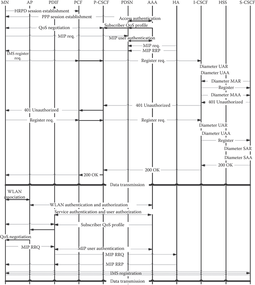
FIGURE 36.8 Flow diagram of user moving from CDMA2000 to WLAN while using IMS.
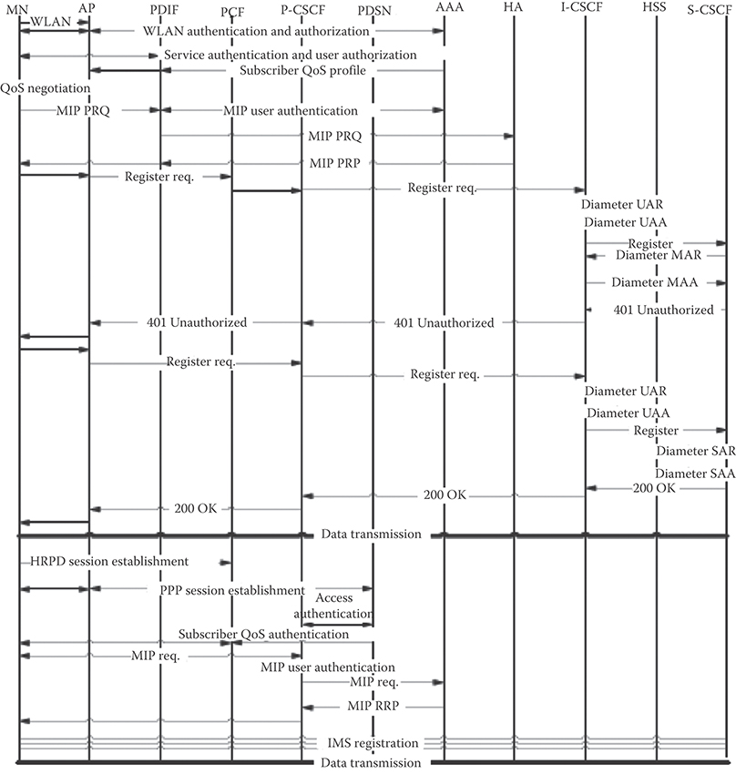
FIGURE 36.9 Flow diagram of user moving from WLAN to CDMA2000 while using IMS.
where R is the fluid flow rate of registration and A is the number of access to each of the IMS entities. For the random walk model, a MATLABℓ simulation model is used, cell residence time is assumed to be exponentially distributed. The duration of calls is exponential with mean equal to 1/µ and new call arrival to the mobile terminal is a Poisson process with rate λ. The call-to-mobility ratio represents the average number of calls the user receives divided by the average number of registration areas visited by the user. The CMR is assumed to be equal to 5. Figure 36.10 shows the number of accesses to IMS servers (P-CSCF, I-CSCF, and S-CSCF) per second with pure CDMA2000 network taking into consideration the existence of hot spots. We assume that the user mobility within the hotspots follows fluid flow model. The figure shows that the rate of accesses to the IMS servers actually decreases with increasing hot spot radius. The reason for the decrease in rate is due to the fact that the users move slowly within a hot spot than within the CDMA2000 network. WLAN deployment in these areas will be based on customer demands and needs. We assume that in order to enhance the service offering WLAN is considered integrated with the CDMA2000 network, Figure 36.11 shows the incremental access rate to the IMS servers and CDMA2000 servers per second with the hybrid network case incorporating WLANs. As the area increases the number of users within the WLAN increases which increases the crossing rate. As the figure shows, the P-CSCF and the S-CSCF process the added signaling. However, since the I-CSCF sever reroutes incoming queries to the S-CSCF server or other networks and also accesses the HSS server, it is affected the most, processing maximum number of additional queries among the IMS servers [18].
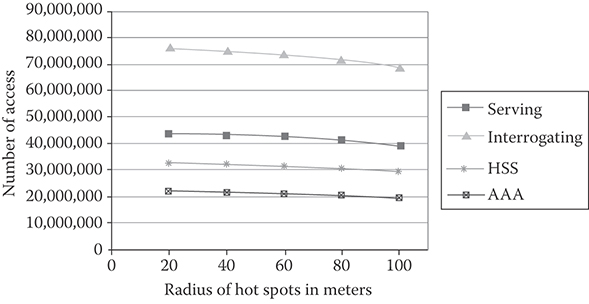
FIGURE 36.10 Rate of access to the IMS servers prior to the deployment of WLANs.

FIGURE 36.11 The increased rate of access to the IMS servers over Figure 36.10 due to WLAN deployment.
36.4 Conclusions
The analysis in Section 36.3 reveals that the rate of queries/updates to services due to service requests initiated by users can be an order of magnitude more than that due to registration activity alone. As the number of services increases, and along with it the associated signaling, it is clear that heavy load will be placed on the IMS servers, which must therefore be designed to handle the load. The analysis also reveals that user mobility patterns influence the signaling load. For example, assuming suitable shape and scale parameters, one can show that Gamma distribution can place three times as much load on IMS servers due to registration signaling as does the fluid flow mobility model. Consequently, network engineers must ensure that they take into account appropriate user mobility patterns. The analysis also reveals that S-CSCF is loaded the most among the IMS servers due to service requests while I-CSCF is loaded the most during registration [19].
The analysis further provides insight into the impact on signaling due to the integration of IMS with a CDMA2000 and WLAN hybrid network. Two types of mobility are considered: the first one represents the movement of the user from CDMA2000 to WLAN and the second one represents the movement from WLAN to CDMA2000. The integration is analyzed using fluid flow for the first scenario and random walk for the second scenario; assumptions are made concerning a service provider's deployment. A MATLAB simulation model is utilized for the random walk model to analyze the rate of accesses to the IMS servers. The results reveal that integrating CDMA2000 with WLAN will increase the signaling to IMS servers. The number of accesses to the servers may vary depending on the assumptions made.
The analysis provides network designers insights into the size of the IMS servers required to support WLAN and 3G users by determining the overall load on the system. It provides designers with the necessary tools to scale the IMS system with growth in the number of users, and usage rate. To reproduce such analysis, the designer should determine the user mobility behavior, and based on the mobility model(s), the number of the boundary crossings. Knowing the rate of boundary crossings by users, the number of registrations initiated by users from one network to another can be estimated and subsequently, by determining the number of queries to each server, the registration load can be determined. The analysis is targeted mainly to help IMS network designers and architects and therefore the flow diagram only takes into consideration the IMS entities.
Acknowledgment
This research was supported in part by the National Science Foundation Grant EPS-0701890.
References
1. 3rd Generation Partnership Project (3GPP), IP Multimedia Subsystem (IMS), TS23.228, Rel10.
2. http://www.openmobilealliance.org/.
3. M. Poikselka, G. Mayer, H. Khartabil, and A. Niemi, The IMS IP Multimedia Concepts and Services for the Mobile Domain, Wiley, 2004, ISBN 0-470-87113-X.
4. G. Camarillo and M. Garcia-Martin, The 3G IP Multimedia Subsystem (IMS), John Wiley, 2006, ISBN 0-470-01818-6.
5. M. Koukal and R. Bestak, Architecture of IP multimedia subsystem, Proceedings of the 48th International Symposium, Zadar, Croatia, pp. 323–326, 2006.
6. F. Cuervo, N. Greene, A. Rayhan, C. Huitema, B. Rosen, and J. Segers, Megaco protocol version 1.0, IETF RFC Request for Comments: 3015, November 2000.
7. Internet Engineering Task Force (IETF), Session initiation protocol (SIP), RFC 3261, June 2002.
8. M. Wuthnow, M. Stafford, and J. Shih, IMS A New Model for Blending Applications, Informal Telecoms & Media, 2009.
9. U. Iqbal, S. Sohail, and M. Javed, SIP based QoS management architecture for IP multimedia subsystems over IP access networks, World Academy of Science, Engineering and Technology, 64, 2010.
10. S. Blake, D. Black, M. Carlson, E. Davies, Z. Wang, and W. Weiss, An architecture for differentiated services, IETF RFC Request for Comments, December, 2475, 1998.
11. Z. Bei, Analysis of SIP in UMTS IP multimedia subsystem, PhD thesis, North Carolina State University, USA, p. 91, 2003.
12. W. Wang and I. Akyildiz, intersystem location update and paging schemes for multitier wireless networks, International Conference on Mobile Computing and Networking, Massachusetts, USA, 2000, pp. 99–109.
13. S. Mohan and R. Jain, Two user location strategies for personal communications services IEEE Personal Communications, 1, 42–50, 1994.
14. D. Dunwang, L. Xia, and Z. Hua, Study of multi-connection mechanism in IMS, Communications and Mobile Computing (CMC) International Conference, Shenzhen, China, vol. 1, pp. 345–349, 2010.
15. J. Xiao, C. Huang, and J. Yan, A flow-based traffic model for SIP messages in IMS IEEE GLOBCOM 09, pp. 1–7, 2009.
16. M. Buddhikot, G. Chandranmenon , Design and implementation of a WLAN/CDMA2000 interworking architecture, IEEE Communications Magazine, 41, 90–100, 2003.
17. H. Mahmood and B. Gage, An architecture for integrating CDMA2000 and 802.11 WLAN Networks, IEEE 58th Vehicular Technology Conference, VTC2003, vol. 3, 2003.
18. L. Saleem, R. Ghimire, and S. Mohan, An analysis of IP multimedia subsystems for a hybrid network, IEEE 4th International Conference on Internet Multimedia Services Architecture and Applications (IMSAA), Bangalore, India, pp. 1–6, 2010.
19. L. Saleem and S. Mohan, A complexity analysis of IP multimedia subsystems (IMS), First International Symposium on Advanced Networks and Telecommunications Systems (ANTS), Mumbai, India, December 2007.