
Chapter 7. Antenna Design
Radio waves are actually photons. We almost always deal with their wave-like properties, but we can discuss them the same way we discuss light. First is that, if you focus a light source, you increase its power in the direction focused, at the cost of reducing its visibility from other sides. This is a key point of antennas. Second is that, like camera lenses and telescopes, larger antennas tend to capture more radio signal than smaller antennas. Finally, as with audio speakers, you need to make the fundamental size of your antenna match the frequency of the radio waves you are using.
Fortunately, your task is easier than that of a general radio user, since your satellite will be broadcasting at or near a single specific frequency. Therefore, once you build and match your transmitter and receiver, you do not have to worry about varying it later. Although you have to do some initial hardware research, once you build your setup, it will be stable.
Antenna Shape
We call a standard rod-like antenna a dipole. There are also circular antennas and other designs, but the bulk of satellite work uses dipoles. An antenna is a dipole because you apply voltage at one end so it has a positive and negative point.
Magnetic dipoles
Magnets are also dipoles because they have a plus at one end and a minus at the other. Dipoles abound in physics and in nature.
An antenna can be omnidirectional, which means that it broadcasts and receives signals from all directions at low efficiency. Or the antenna can be directional, which means it boosts its efficiency in the direction it is pointing, but has really poor performance in any other direction. A dipole antenna is a nearly omni-directional antenna, tending to send signals strongly all along the horizontal plane, but sending not as much signal in the up-down direction.
In satellites, these are often called low-gain and high-gain antennas. The omnidirectional low-gain antenna doesn’t require any specific pointing, but is weaker. The high-gain antenna only works if pointing in the direction of your ground station, but when it works it has a much stronger signal. The primary difference is shape. A high-gain antenna involves shaping the antenna to focus radio signals in one direction (gain) at the cost of having less radio in all other directions.
This kind of big high-gain antenna, the Capitol Technology University Big Dish, is what we want:

whereas this handheld rig is more like what we can get into space: a small, low-gain antenna:

An omnidirectional antenna or low-gain antenna or dipole antenna can be just a single metal bar or strip. A car radio aerial or the antenna on a walkie-talkie are examples of (nearly) omni-directional antennas. In practice, a straight aerial of that sort isn’t fully omnidirectional. Instead, it captures signals coming from the full 360 degrees around it, but is a poor receiver along the direction it is pointing.
This leads to the basic rule of directionality. An antenna works best if roughly broadside to the signal. If you point a straight rod straight at your radio target, the signal is weak because you don’t have a large capture area for the radio waves. If you put the antenna so its entire length can receive radio waves from the direction of the source, you are maximizing your signal. In this way, antennas behave more like sails on a sailboat—the more your antenna has a capture area facing the direction of the signals, the more signals your antenna absorbs. A dish or a Yagi are examples of high-gain antennas.
Common Spacecraft Antenna
It is most likely your satellite will use one or more low-gain omni-directional antennas to broadcast uniformly in all directions, while your ground station will use a directional antenna that actively tracks and points at the satellite. This makes the satellite easy to use—you do not have to worry about what direction it is facing—while improving response at the ground station—which can afford the cost and weight of fancier equipment.
Most amateur satellites do not have active attitude control, which means they lack the ability to control which direction they face. Therefore, most amateur satellites use one or more omni-directional low-gain antennas to broadcast in all directions, accepting that the signal is weaker but ensuring that the satellite can be heard from the ground regardless of how it is facing.
Even a single antenna will see the ground often. A common configuration is to stick two or four antennas off the base of the satellite, so that even if the satellite is tumbling, at least one or more antenna will have a good facing to the ground. In many ways, having consistent reception is more important for CubeSats than having a high efficiency in reception. It is better that the data always comes through, even if slowly, than to have dropouts that lead to gaps in the data.
Most NASA and commercial missions, in contrast, have attitude control and specifically use a high-gain antenna that is always pointed towards the ground station, to ensure stronger radio signal power—which translates to higher data rates. As a backup, they all include a low-gain omnidirectional antenna, useful if there is a satellite problem that errs and points the high-gain antenna the wrong way. Low gain = reliable, high gain = efficient.
Common Ground Station Antenna
Meanwhile, on the ground, for satellites, you will likely skip the omni and instead use a directional antenna such as a Yagi. A Yagi is one common design for a directional antenna, and looks a bit like the love child between a weather vane and an arrow. You point the antenna support in the direction you need so that all of the vanes that are sticking out sideways can draw signal. It gets great performance, but signals to the side are essentially ignored. A handheld Yagi antenna from the side:

and rotated to show the top:
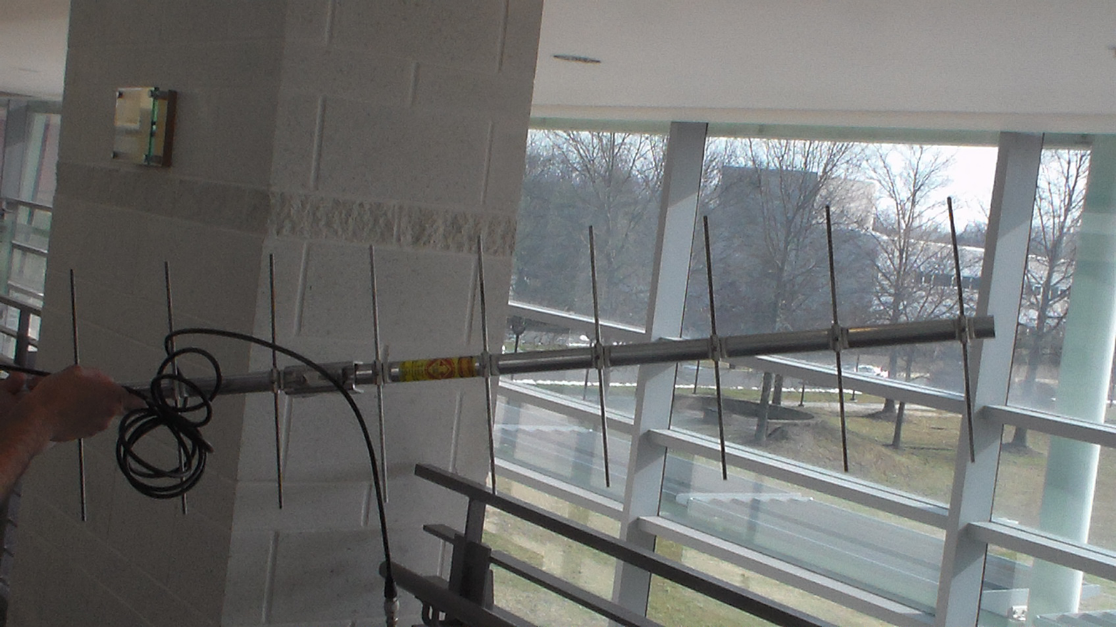
In both cases, the strongest reception is in the direction the arrow-like antenna is pointed, and it gets very poor performance from the sides.
If your ground antenna is directional, you need to know where your satellite is so you can point (orient) your antenna properly. This involves three steps:
-
Directional antenna mounted on a motorized, computer-controlled mount
-
Software to control the antenna rotator
-
Orbital elements for your satellite so you can deduce where to point
You can often do these items by hand. If you know, for example, that the International Space Station (ISS) is going to rise in the west at 9:10 and set in the east at 9:14, you can easily manually track it. There are many websites that list how to visually spot the ISS, so I recommend you first do that before trying to track it with radio. The technique is the same:
-
Look up the transit position for ISS.
-
When it appears (location and time), wait until it comes over the horizon, do the initial Acquisition.
-
Track its eye as it moves.
-
When it falls below the horizon or moves into the Earth’s shadow, you are done.
Two sites with more ISS (and other satellite) tracking information are Spot the Station and SATFLARE, among others. Satellite spotting is a fun activity and the Internet is full of helpful predictions to tell you when and where to find all sorts of satellite activity.
Note
If you’re interested, also look up Iridium flares for details on spotting the tiny yet shiny constellation of Iridium satellites.
Once you’ve done the spotting visually, you are ready to try radio spotting. Unlike visual spotting, which can be done only at night or twilight, radio spotting can be done day or night. Armed with your direction antenna, you will:
-
Look up the transit position for ISS.
-
When it appears, point your antenna at the horizon and wait for AOS.
-
Track ISS so that you always have a strong signal.
-
When ISS falls below the horizon (LOS), you are done.
The only difference between the two methods is that you aren’t visually spotting the space station, but using the radio signal strength to keep on target. This is easier to do than describe. You just keep moving the antenna and if the signal gets weaker, you are either leading it by too much, or lagging too slowly. Despite the name directional, a decent Yagi has a broad enough beam that you do not need high accuracy to pull this off.
The first time you track ISS, try doing it at night so you can also visually spot the station. Once you get the hang of it, it’s easy to do anytime. If you can track the ISS, you can track a satellite. Once you build the fancier automated tracking rig mentioned above, you can test it by robo-tracking the ISS with your new setup.
Antenna Size and Frequency
The second quality of an antenna is that it has to be built to the frequency (or wavelength) of radio it can pick up. If you hit the different blocks of an xylophone, each makes a distinct tone or pitch—the longer blocks make lower pitches, the higher blocks make higher pitches. Antennas similarly have to be the right size to resonate and pick up their specific radio frequencies.
The rule of thumb is your antenna length should be a ratio of the wavelength you want to receive, ideally half the wavelength, if not some power-of-two fraction of it. The reason is you want the incoming radio wave to drive the antenna at its ideal frequency, so it can deposit the most power into it.
Impedance and SWR
The material and the cables connecting the antenna form a circuit. All circuits have some amount of resistance and some impedance. Resistance is exactly as it sounds, resistance to the flow of electricity. Even the conductors we are using have some resistance (superconducting antennae are left as an exercise for the reader). Impedance is, roughly, the sluggishness in how quickly the antenna or circuit responds to a change in voltage or current.
An antenna is made of a material (metal) that reacts strongly to radio waves, cut to the length so that the wave maximizes its driving influence. Without going too deep into antenna theory, there are nonresonant and multifrequency designs as well, but for CubeSat low-power operations, we want to make an optimized yet simple antenna that maximizes signal and minimizes losses.
The term impedance is used as a measure of how closely changes in voltage are matched by the change in current. If you apply a current (signal) to an antenna and the voltage changes in phase, the antenna power is being radiated (or, if a receiver, absorbed). If the response of the antenna lags the voltage change, the power of the signal is stored in the antenna’s electromagnetic field instead of being radiated out. The ideal impedance is neither too large nor too small, and is related using a term called standing wave ratio (SWR).
SWR is a measure of your antenna’s efficiency, and is the difference between the transmitted forward energy and any stored or reflected energy. We also introduce the term isotropic effective radio power (ERP), which ideally will be 100%, that is 100% of the energy you are pushing into the antenna manifests as radio waves going in all directions. (For now, we are ignoring antenna shapes and directionality.)
SWR = Forward - Reflected + (Reflected/Forward)
SWR is measured with (of course) an SWR meter as part of your radio gear, usually as a separate box installed between the antenna and the radio. You will use an SWR meter for your ground station. You will temporarily hook one up to your satellite while testing and tuning your system, but definitely remove it before launch. There is no point in flying a meter in space that no one can read!
SWR is given as a ratio (e.g., 1.0:1 = 0% loss, 100% ERP). A SWR of 1.0 indicates the antenna is perfectly matched to your signal line. At 3.0:1, there is 25% loss so the ERP is 75%. At 6.0:1, you are at 51% loss and 49.0% power, and higher than that isn’t worth using. Most advice says to try for 1.2:1 or less, and anything above 3 is usually marked in red on your meter.
(What happens to the nonradiated stored power? It tends to cause interference in both the connected electronics and via radio emission at other frequencies dumping into nearby other electronics. Not good.)
The hardware to match impedance is technical and varied, including antenna tuners (a powered box to help match impedance), choosing the right wire, balun transformers, and proper choice of wire. At this point you should look at the ARRL Antenna Book or any of the fine web ham resources for exact design. Antenna design depends on frequency, use, and hardware limits.
Antenna Materials
ERP_ = (Power of transmitter) - Losses + Antenna Gain
versus a dipole antenna.
EIRP = (Power of transmitter) - Losses + Antenna Gain
versus an ideal isotropic antenna.
Many amateur CubeSats use an onboard antenna consisting of two or four wire strips, cut to the length of one-half, one-fourth, or one-eighth the wavelength (depending on their frequency). The 70 cm band is a common range, typically using frequencies of 430-450 MHz (depending on each country’s licensing). A one-half wavelength antenna is therefore 35 cm, or just under 14 inches.
These straight antenna can be made from a hardware store metal tape measure, the roll of metal ruler stored in a box. One plus of using a tape measure is you don’t have to use a separate ruler to cut off just the right length—but you should remove any paint or coatings from the metal. An antenna works best if it is the bare metal, with no covering, like the tape in this tape measure (photo credit: Evan-Amos):

A bonus of using tape measure antenna is that you can (and will) roll the antenna up into the satellite for launch, and rely on the fact that it will spring back out to its full length once the satellite is kicked away from the launch vehicle. Presto, antenna and deployment system already designed for you.
Using that design, you can easily deploy four antenna in a cross pattern, or two antenna as opposite sides. For material, you take a cleaned, unpainted, stripped metal tape measure, cut off the proper length, then roll it up inside the cube before launch. When the satellite launches, the antenna immediately uncoils to its straight length, then sits there happily until you eventually get around to powering up the satellite.
Fancier antenna exist, including coiled designs and models made specifically for CubeSats. The principles are the same: match the antenna to the wavelength (in size) and the circuit (based on the frequency and the hardware and connecting wires you are using). Build a ground station that can receive that same frequency. Allow some frequency variation for Doppler shift. Test, test, test. Then launch.
A short summary for a typical amateur satellite is:
-
Omni for satellite: tape measures
-
Directional for ground: Yagi on a motorized mount, computer, software
-
Orbital elements: from web
Power, ERP, and EIRP
We talk about the power of the antenna, for example, that we are using a 0.5 watt transmitter, so that’s our transmitter power or output power. Effective isotropic radio power (EIRP) and effective radio power (ERP), mentioned earlier, include any losses due to the circuits and wiring, and any boost if you are using a directional antenna.
The ERP is calculated, in dB, as the power minus the losses (as usual) plus gain, and is compared for your antenna shape against a hypothetical dipole antenna. It’s a measure of your actual power, versus the lower power you would have if you just used a dipole antenna—specifically, an ideal half-wave dipole antenna that provides a little gain. Because we are using dB, a logarithmic unit, we’re adding each component:
ERP = (Power of transmitter) – Losses + Antenna gain
versus a dipole antenna.
The EIRP is nearly identical, but tells you your power relative to an ideal isotropic antenna—which has no gain or signal boost in any direction—instead of a dipole (which has a little gain in some directions):
EIRP = (Power of transmitter) – Losses + Antenna gain
versus an ideal isotropic antenna.
Both of these are ways of saying how your specific antenna shape—which has a gain—compares to a low-gain (dipole) or isotropic (no gain and radiates equally in all direction) antenna. So both are slightly larger than those lower-efficiency designs. Note that if you had a theoretically lossless circuit and an antenna with no losses that radiated its power perfectly isotropically (in all directions), the ERP would be equal to the transmitter power. You can think of transmitter power as power applied and ERP or EIRP as maximum power delivered.
From a licensing and use level, this means both ERP and EIRP are the power a receiver can, at best, expect to face. It is therefore a very useful measure. While transmitter power says what the circuits put out, ERP says what the circuits + antenna actually are able to deliver. It’s a more useful number when you’re trying to figure out what to expect at the receiver.
So to use the Wikipedia.org “Effective Radiate Power” figures as an example, if your transmitter is putting out 0.5 watts, and your circuit + antenna have a 6 dB loss but the directional antenna provides a 9 dB gain (for listeners facing it), then the ERP = +9 dB – 6Db = +3 dB ERP gain, or roughly a 2x boost on the 0.5 watts, so the ERP = 1 Watt. Notice that, if you’re not facing the antenna, you are receiving far less than this, but ERP is usually assumed to be the maximum power anyone might experience.
As a side note, ERP = EIRP/1.64, because 1.64 is the gain difference between an ideal dipole versus an ideal isotropic antenna. Put another way, an isotropic antenna has no gain (amplification factor = 1), while a dipole has a gain of 1.64 (amplification of 1.64) if you face it just the right way. From a functional level, ERP is important for licensing because if you exceed the ERP allowed, you are violating the FCC (or your local country’s equivalent) rules and have to shut down your transmitter.