
Database technology has evolved rapidly in the three decades since the rise and eventual dominance of relational database systems. While many specialized database systems (object-oriented, spatial, multimedia, etc.) have found substantial user communities in the science and engineering fields, relational systems remain the dominant database technology for business enterprises.
Relational database design has evolved from an art to a science that has been made partially implementable as a set of software design aids. Many of these design aids have appeared as the database component of computer-aided software engineering (CASE) tools, and many of them offer interactive modeling capability using a simplified data modeling approach. Logical design—that is, the structure of basic data relationships and their definition in a particular database system—is largely the domain of application designers. These designers can work effectively with tools such as ERwin Data Modeler or Rational Rose with UML, as well as with a purely manual approach. Physical design, the creation of efficient data storage and retrieval mechanisms on the computing platform being used, is typically the domain of the database administrator (DBA). Today’s DBAs have a variety of vendor-supplied tools available to help design the most efficient databases. This book is devoted to the logical design methodologies and tools most popular for relational databases today. Physical design methodologies and tools are covered in a separate book.
In this chapter, we review the basic concepts of database management and introduce the role of data modeling and database design in the database life cycle.
1.1 Data and Database Management
The basic component of a file in a file system is a data item, which is the smallest named unit of data that has meaning in the real world—for example, last name, first name, street address, ID number, or political party. A group of related data items treated as a single unit by an application is called a record. Examples of types of records are order, salesperson, customer, product, and department. A file is a collection of records of a single type. Database systems have built upon and expanded these definitions: In a relational database, a data item is called a column or attribute; a record is called a row or tuple; and a file is called a table.
A database is a more complex object; it is a collection of interrelated stored data that serves the needs of multiple users within one or more organizations, that is, interrelated collections of many different types of tables. The motivations for using databases rather than files include greater availability to a diverse set of users, integration of data for easier access to and updating of complex transactions, and less redundancy of data.
A database management system (DBMS) is a generalized software system for manipulating databases. A DBMS supports a logical view (schema, subschema); physical view (access methods, data clustering); data definition language; data manipulation language; and important utilities, such as transaction management and concurrency control, data integrity, crash recovery, and security. Relational database systems, the dominant type of systems for well-formatted business databases, also provide a greater degree of data independence than the earlier hierarchical and network (CODASYL) database management systems. Data independence is the ability to make changes in either the logical or physical structure of the database without requiring reprogramming of application programs. It also makes database conversion and reorganization much easier. Relational DBMSs provide a much higher degree of data independence than previous systems; they are the focus of our discussion on data modeling.
1.2 The Database Life Cycle
The database life cycle incorporates the basic steps involved in designing a global schema of the logical database, allocating data across a computer network, and defining local DBMS-specific schemas. Once the design is completed, the life cycle continues with database implementation and maintenance. This chapter contains an overview of the database life cycle, as shown in Figure 1.1. In succeeding chapters, we will focus on the database design process from the modeling of requirements through logical design (steps I and II below). The result of each step of the life cycle is illustrated with a series of diagrams in Figure 1.2. Each diagram shows a possible form of the output of each step, so the reader can see the progression of the design process from an idea to actual database implementation. These forms are discussed in much more detail in Chapters 2 through 6.
I. Requirements analysis. The database requirements are determined by interviewing both the producers and users of data and using the information to produce a formal requirements specification. That specification includes the data required for processing, the natural data relationships, and the software platform for the database implementation. As an example, Figure 1.2 (step I) shows the concepts of products, customers, salespersons, and orders being formulated in the mind of the end user during the interview process.
II. Logical design. The global schema, a conceptual data model diagram that shows all the data and their relationships, is developed using techniques such as ER or UML. The data model constructs must ultimately be transformed into normalized (global) relations, or tables. The global schema development methodology is the same for either a distributed or centralized database.
a. Conceptual data modeling. The data requirements are analyzed and modeled using an ER or UML diagram that includes, for example, semantics for optional relationships, ternary relationships, supertypes, and subtypes (categories). Processing requirements are typically specified using natural language expressions or SQL commands, along with the frequency of occurrence. Figure 1.2 [step II(a)] shows a possible ER model representation of the product/customer database in the mind of the end user.

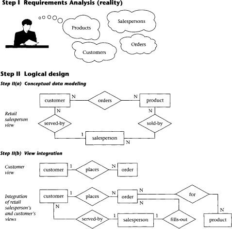

Figure 1.2 Life cycle results, step-by-step
b. View integration. Usually, when the design is large and more than one person is involved in requirements analysis, multiple views of data and relationships result. To eliminate redundancy and inconsistency from the model, these views must eventually be “rationalized” (resolving inconsistencies due to variance in taxonomy, context, or perception) and then consolidated into a single global view. View integration requires the use of ER semantic tools such as identification of synonyms, aggregation, and generalization. In Figure 1.2 [step II(b)], two possible views of the product/customer database are merged into a single global view based on common data for customer and order. View integration is also important for application integration.
c. Transformation of the conceptual data model to SQL tables. Based on a categorization of data modeling constructs and a set of mapping rules, each relationship and its associated entities are transformed into a set of DBMS-specific candidate relational tables. We will show these transformations in standard SQL in Chapter 5. Redundant tables are eliminated as part of this process. In our example, the tables in step II(c) of Figure 1.2 are the result of transformation of the integrated ER model in step II(b).
d. Normalization of tables. Functional dependencies (FDs) are derived from the conceptual data model diagram and the semantics of data relationships in the requirements analysis. They represent the dependencies among data elements that are unique identifiers (keys) of entities. Additional FDs that represent the dependencies among key and nonkey attributes within entities can be derived from the requirements specification. Candidate relational tables associated with all derived FDs are normalized (i.e., modified by decomposing or splitting tables into smaller tables) using standard techniques. Finally, redundancies in the data in normalized candidate tables are analyzed further for possible elimination, with the constraint that data integrity must be preserved. An example of normalization of the Salesperson table into the new Salesperson and SalesVacations tables is shown in Figure 1.2 from step II(c) to step II(d).
III. Physical design. The physical design step involves the selection of indexes (access methods), partitioning, and clustering of data. The logical design methodology in step II simplifies the approach to designing large relational databases by reducing the number of data dependencies that need to be analyzed. This is accomplished by inserting conceptual data modeling and integration steps [steps II(a) and II(b) of Figure 1.2] into the traditional relational design approach. The objective of these steps is an accurate representation of reality. Data integrity is preserved through normalization of the candidate tables created when the conceptual data model is transformed into a relational model. The purpose of physical design is to optimize performance as closely as possible.
As part of the physical design, the global schema can sometimes be refined in limited ways to reflect processing (query and transaction) requirements if there are obvious, large gains to be made in efficiency. This is called denormalization. It consists of selecting dominant processes on the basis of high frequency, high volume, or explicit priority; defining simple extensions to tables that will improve query performance; evaluating total cost for query, update, and storage; and considering the side effects, such as possible loss of integrity. This is particularly important for Online Analytical Processing (OLAP) applications.
IV. Database implementation, monitoring, and modification. Once the design is completed, the database can be created through implementation of the formal schema using the data definition language (DDL) of a DBMS. Then the data manipulation language (DML) can be used to query and update the database, as well as to set up indexes and establish constraints, such as referential integrity. The language SQL contains both DDL and DML constructs; for example, the create table command represents DDL, and the select command represents DML.
As the database begins operation, monitoring indicates whether performance requirements are being met. If they are not being satisfied, modifications should be made to improve performance. Other modifications may be necessary when requirements change or when the end users’ expectations increase with good performance. Thus, the life cycle continues with monitoring, redesign, and modifications. In the next two chapters we look first at the basic data modeling concepts and then—starting in Chapter 4—we apply these concepts to the database design process.
1.3 Conceptual Data Modeling
Conceptual data modeling is the driving component of logical database design. Let us take a look at how this component came about, and why it is important. Schema diagrams were formalized in the 1960s by Charles Bachman. He used rectangles to denote record types and directed arrows from one record type to another to denote a one-to-many relationship among instances of records of the two types. The entity-relationship (ER) approach for conceptual data modeling, one of the two approaches emphasized in this book and described in detail in Chapter 2, was first presented in 1976 by Peter Chen. The Chen form of the ER model uses rectangles to specify entities, which are somewhat analogous to records. It also uses diamond-shaped objects to represent the various types of relationships, which are differentiated by numbers or letters placed on the lines connecting the diamonds to the rectangles.
The Unified Modeling Language (UML) was introduced in 1997 by Grady Booch and James Rumbaugh and has become a standard graphical language for specifying and documenting large-scale software systems. The data modeling component of UML (now UML-2) has a great deal of similarity with the ER model and will be presented in detail in Chapter 3. We will use both the ER model and UML to illustrate the data modeling and logical database design examples throughout this book.
In conceptual data modeling, the overriding emphasis is on simplicity and readability. The goal of conceptual schema design, where the ER and UML approaches are most useful, is to capture real-world data requirements in a simple and meaningful way that is understandable by both the database designer and the end user. The end user is the person responsible for accessing the database and executing queries and updates through the use of DBMS software, and therefore has a vested interest in the database design process.
The ER model has two levels of definition—one that is quite simple and another that is considerably more complex. The simple level is the one used by most current design tools. It is quite helpful to the database designer who must communicate with end users about their data requirements. At this level you simply describe, in diagram form, the entities, attributes, and relationships that occur in the system to be conceptualized, using semantics that are definable in a data dictionary. Specialized constructs, such as “weak” entities or mandatory/optional existence notation, are also usually included in the simple form. But very little else is included, to avoid cluttering up the ER diagram while the designer’s and end user’s understandings of the model are being reconciled.
An example of a simple form of ER model using the Chen notation is shown in Figure 1.3. In this example, we want to keep track of videotapes and customers in a video store. Videos and customers are represented as entities Video and Customer, and the relationship “rents” shows a many-to-many association between them. Both Video and Customer entities have a few attributes that describe their characteristics, and the relationship “rents” has an attribute due date that represents the date that a particular video rented by a specific customer must be returned.

Figure 1.3 A simple form of ER model using the Chen notation
From the database practitioner’s standpoint, the simple form of the ER model (or UML) is the preferred form for both data modeling and end user verification. It is easy to learn and applicable to a wide variety of design problems that might be encountered in industry and small businesses. As we will demonstrate, the simple form can be easily translated into SQL data definitions, and thus it has an immediate use as an aid for database implementation.
The complex level of ER model definition includes concepts that go well beyond the simple model. It includes concepts from the semantic models of artificial intelligence and from competing conceptual data models. Data modeling at this level helps the database designer capture more semantics without having to resort to narrative explanations. It is also useful to the database application programmer, because certain integrity constraints defined in the ER model relate directly to code—code that checks range limits on data values and null values, for example. However, such detail in very large data model diagrams actually detracts from end user understanding. Therefore, the simple level is recommended as the basic communication tool for database design verification.
1.4 Summary
Knowledge of data modeling and database design techniques is important for database practitioners and application developers. The database life cycle shows the steps needed in a methodical approach to designing a database,, from logical design, which is independent of the system environment, to physical design, which is based on the details of the database management system chosen to implement the database. Among the variety of data modeling approaches, the ER and UML data models are arguably the most popular ones in use today, due to their simplicity and readability. A simple form of these models is used in most design tools; it is easy to learn and to apply to a variety of industrial and business applications. It is also a very useful tool for communicating with the end user about the conceptual model and for verifying the assumptions made in the modeling process. A more complex form, a superset of the simple form, is useful for the more experienced designer who wants to capture greater semantic detail in diagram form, while avoiding having to write long and tedious narrative to explain certain requirements and constraints.
1.5 Literature Summary
Much of the early data modeling work was done by Bachman [1969, 1972], Chen [1976], Senko et al. [1973], and others. Database design textbooks that adhere to a significant portion of the relational database life cycle described in this chapter are Teorey and Fry [1982], Muller [1999], Stephens and Plew [2000], Simsion and Witt [2001], and Hernandez and Getz [2003]. Temporal (time-varying) databases are defined and discussed in Jensen and Snodgrass [1996] and Snodgrass [2000]. Other well used approaches for conceptual data modeling include IDEF1X [Bruce, 1992; IDEF1X, 2005] and the data modeling component of the Zachmann Framework [Zachmann, 1987; Zachmann Institute for Framework Advancement, 2005]. Schema evolution during development, a frequently occurring problem, is addressed in Harriman, Hodgetts, and Leo [2004].