3 The Unified Modeling Language (UML)
The Unified Modeling Language (UML) is a graphical language for communicating design specifications for software. The object-oriented software development community created UML to meet the special needs of describing object-oriented software design. UML has grown into a standard for the design of digital systems in general.
There are a number of different types of UML diagrams serving various purposes [Rumb05]. The class and activity diagram types are particularly useful for discussing database design issues. UML class diagrams capture the structural aspects found in database schemas. UML activity diagrams facilitate discussion on the dynamic processes involved in database design. This chapter is an overview of the syntax and semantics of the UML class and activity diagram constructs used in this book. These same concepts are useful for planning, documenting, discussing and implementing databases. We are using UML 2.0, although for the purposes of the class diagrams and activity diagrams shown in this book, if you are familiar with UML 1.4 or 1.5 you will probably not see any differences.
UML class diagrams and entity-relationship (ER) models [Chen, 1976; Chen, 1987] are similar in both form and semantics. The original creators of UML point out the influence of ER models on the origins of class diagrams [Rumbaugh, Jacobson, and Booch, 2005]. The influence of UML has in turn affected the database community. Class diagrams now appear frequently in the database literature to describe database schemas.
UML activity diagrams are similar in purpose to flowcharts. Processes are partitioned into constituent activities along with control flow specifications.
This chapter is organized into three sections. Section 3.1 presents class diagram notation, along with examples. Section 3.2 covers activity diagram notation, along with illustrative examples. Section 3.3 concludes with a few rules of thumb for UML usage.
3.1 Class Diagrams
A class is a descriptor for a set of objects that share some attributes and/or operations. We conceptualize classes of objects in our everyday lives. For example, a car has attributes, such as vehicle identification number (VIN) and mileage. A car also has operations, such as accelerate and brake. All cars have these attributes and operations. Individual cars differ in the details. A given car has its own values for VIN and mileage. For example, a given car might have VIN 1NXBR32ES3Z126369 and a mileage of 22,137 miles. Individual cars are objects that are instances of the class “Car.”
Classes and objects are a natural way of conceptualizing the world around us. The concepts of classes and objects are also the paradigms that form the foundation of object-oriented programming. The development of object-oriented programming led to the need for a language to describe object-oriented design, giving rise to UML.
There is a close correspondence between class diagrams in UML and ER diagrams. Classes are analogous to entities. Database schemas can be diagrammed using UML. It is possible to conceptualize a database table as a class. The columns in the table are the attributes, and the rows are objects of that class. For example, we could have a table named “Car” with columns named “vin” and “mileage.” Each row in the table would have values for these columns, representing an individual car. A given car might be represented by a row with the value “1NXBR32ES3Z126369” in the vin column, and 22,137 in the mileage column.
The major difference between classes and entities is the lack of operations in entities. Note that the term operation is used here in the UML sense of the word. Stored procedures, functions, triggers, and constraints are forms of named behavior that can be defined in databases; however these are not associated with the behavior of individual rows. The term operations in UML refers to the methods inherent in classes of objects. These behaviors are not stored in the definition of rows within the database. There are no operations named “accelerate” or “brake” associated with rows in our “Car” table. Classes can be shown with attributes and no operations in UML, which is the typical usage for database schemas.
3.1.1 Basic Class Diagram Notation
The top of Figure 3.1 illustrates the UML syntax for a class, showing both attributes and operations. It is also possible to include user-defined named compartments, such as responsibilities. We will focus on the class name, attributes, and operations compartments. The UML icon for a class is a rectangle. When the class is shown with attributes and operations, the rectangle is subdivided into three horizontal compartments. The top compartment contains the class name, centered in bold face, beginning with a capital letter. Typically, class names are nouns. The middle compartment contains attribute names, left-justified in regular face, beginning with a lowercase letter. The bottom compartment contains operation names, left-justified in regular face, beginning with a lowercase letter, ending with a parenthetical expression. The parentheses may contain arguments for the operation.
The class notation has some variations reflecting emphasis. Classes can be written without the attribute compartment and/or the operations compartment. Operations are important in software. If the software designer wishes to focus on the operations, the class can be shown with only the class name and operations compartments. Showing operations and hiding attributes is a very common syntax used by software designers. Database designers, on the other hand, do not generally deal with class operations; however, the attributes are of paramount importance. The needs of the database designer can be met by writing the class with only the class name and attribute compartments showing. Hiding operations and showing attributes is an uncommon syntax for a software designer, but it is common for database design. Lastly, in high-level diagrams, it is often desirable to illustrate the relationships of the classes without becoming entangled in the details of the attributes and operations. Classes can be written with just the class name compartment when simplicity is desired.
Various types of relationships may exist between classes. Associations are one type of relationship. The most generic form of association is drawn with a line connecting two classes. For example, in Figure 3.1 there is an association between the class “Car” and the class named “Driver.”

Figure 3.1 Basic UML class diagram constructs
A few types of associations, such as aggregation and composition, are very common. UML has designated symbols for these associations. Aggregation indicates “part of” associations, where the parts have an independent existence. For example, a Car may be part of a Car Pool. The Car also exists on its own, independent of any Car Pool. Another distinguishing feature of aggregation is that the part may be shared among multiple objects. For example, a Car may belong to more than one Car Pool. The aggregation association is indicated with a hollow diamond attached to the class that holds the parts. Figure 3.1 indicates that a Car Pool aggregates Cars.
Composition is another “part of” association in which the parts are strictly owned, not shared. For example, a Frame is part of a single Car. The notation for composition is an association adorned with a solid black diamond attached to the class that owns the parts. Figure 3.1 indicates that a Frame is part of the composition of a Car.
Generalization is another common relationship. For example, Sedan is a type of car. The “Car” class is more general than the “Sedan” class. Generalization is indicated by a solid line adorned with a hollow arrowhead pointing to the more general class. Figure 3.1 shows generalization from the Sedan class to the Car class.
3.1.2 Class Diagrams for Database Design
The reader may be interested in the similarities and differences between UML class diagrams and ER models. Figures 3.2 through 3.5 parallel some of the figures in Chapter 2, allowing for easy comparison. We then turn our attention to capturing primary key information in Figure 3.6. We conclude this section with an example database schema of the music industry, illustrated by Figures 3.7 through 3.10.
Figure 3.2 illustrates UML constructs for relationships with various degrees of association and multiplicities. These examples are parallel to the ER models shown in Figure 2.2. You may refer back to Figure 2.2 if you wish to contrast UML constructs with ER constructs.
Associations between classes may be reflexive, binary or n-ary. Reflexive association is a term we are carrying over from ER modeling. It is not a term defined in UML, although it is worth discussing. Reflexive association relates a class to itself. The reflexive association in Figure 3.2 means an Employee in the role of manager is associated with many managed Employees. The roles of classes in a relationship may be indicated at the ends of the relationship. The number of objects involved in the relationship, referred to as multiplicity, may also be specified at the ends of the relationship. An asterisk indicates that many objects take part in the association at that end of the relationship. The multiplicities of the reflexive association example in Figure 3.2 indicate that an Employee is associated with one manager, and a manager is associated with many managed Employees.

Figure 3.2 Selected UML relationship types (parallel to Figure 2.2)
A binary association is a relationship between two classes. For example, one Division has many Departments. Notice the solid black diamond at the Division end of the relationship. The solid diamond is an adornment to the associations that indicates composition. The Division is composed of Departments.
The ternary relationship in Figure 3.2 is an example of an n-ary association—an association that relates three or more classes. All classes partaking in the association are connected to a hollow diamond. Roles and/or multiplicities are optionally indicated at the ends of the n-ary association. Each end of the ternary association example in Figure 3.2 is marked with an asterisk, signifying many. The meaning of each multiplicity is isolated from the other multiplicities. Given a class, if you have exactly one object from every other class in the association, the multiplicity is the number of associated objects for the given class. One Employee working on one Project assignment uses many Skills. One Employee uses one Skill on many Project assignments. One Skill used on one Project is fulfilled by many Employees.
The next three class diagrams in Figure 3.2 show various combinations of multiplicities. The illustrated one-to-one association specifies that each Department is associated with exactly one Employee acting in the role of manager, and each manager is associated with exactly one Department. The diagram with the one-to-many association means that each Department has many Employees, and each Employee belongs to exactly one Department.
The many-to-many example in Figure 3.2 means each Employee associates with many Projects, and each Project associates with many Employees. This example also illustrates the use of an association class. If an association has attributes, these are written in a class that is attached to the association with a dashed line. The association class named “WorkAssignment” in Figure 3.2 contains two association attributes named “task-assignment” and “start-date.” The association and the class together form an association class.
Multiplicity can be a range of integers, written with the minimum and maximum values separated by two periods. The asterisk by itself carries the same meaning as the range [0 .. *]. Also, if the minimum and maximum are the same number, then the multiplicity can be written as a single number. For example, [1 .. 1] means the same as [1]. Optional existence can be specified using a zero. The [0 .. 1] in the optional existence example of Figure 3.2 means an Employee in the role of manager is associated with either no Department (e.g., is upper management), or one Department.
Mandatory existence is specified whenever a multiplicity begins with a positive integer. The example of mandatory existence in Figure 3.2 means an Employee is an occupant of exactly one Office. One end of an association can indicate mandatory existence, while the other end may use optional existence. This is the case in the example, where an Office may have any number of occupants, including zero.
Generalization is another type of relationship; a superclass is a generalization of a subclass. Specialization is the opposite of generalization; a subclass is a specialization of the superclass. The generalization relationship in UML is written with a hollow arrow pointing from the subclass to the generalized superclass. The top example in Figure 3.3 shows four subclasses: Manager, Engineer, Technician, and Secretary. These four subclasses are all specializations of the more general superclass Employee; that is, Managers, Engineers, Technicians, and Secretaries are types of Employees.
Notice the four relationships share a common arrowhead. Semantically, these are still four separate relationships. The sharing of the arrowhead is permissible in UML, to improve the clarity of the diagrams.
The bottom example in Figure 3.3 illustrates that a class can act as both a subclass in one relationship, and a superclass in another relationship. The class named Individual is a generalization of the Employee and Customer classes. The Employee and Customer classes are in turn superclasses of the EmpCust class. A class can be a subclass in more than one generalization relationship. The meaning in the example is that an EmpCust object is both an Employee and a Customer.

Figure 3.3 UML generalization constructs (parallel to Figure 2.4)
You may occasionally find that UML doesn’t supply a standard symbol for what you are attempting to communicate. UML incorporates some extensibility to accommodate user needs, such as a note. A note in UML is written as a rectangle with a dog-eared upper right corner. The note can attach to the pertinent element(s) with a dashed line(s). Write briefly in the note what you wish to convey. The bottom diagram in Figure 3.3 illustrates a note, which describes the Employee and Customer classes as the “Complete enumeration of subclasses.”
The distinction between composition and aggregation is sometimes elusive for those new to UML. Figure 3.4 shows an example of each, to help clarify. The top diagram means that a Program and Electronic Documentation both contribute to the composition of a Software Product. The composition signifies that the parts do not exist without the Software Product (there is no software pirating in our ideal world). The bottom diagram specifies that a Teacher and a Textbook are aggregated by a course. The aggregation signifies that the Teacher and the Textbook are part of the Course, but they also exist separately. If a Course is canceled, the Teacher and the Textbook continue to exist.


Figure 3.5 UML n-ary relationship (parallel to Figure 2.7)
Figure 3.5 illustrates another example of a n-ary relationship. The n-ary relationship may be clarified by specifying roles next to the participating classes. A Student is an enrollee in a class, associated with a given Room location, scheduled Day, and meeting Time.
The concept of a primary key arises in the context of database design. Often, each row of a table is uniquely identified by the values contained in one or more columns designated as the primary key. Objects in software are not typically identified in this fashion. As a result, UML does not have an icon representing a primary key. However, UML is extensible. The meaning of an element in UML may be extended with a stereotype. Stereotypes are depicted with a short natural language word or phrase, enclosed in guillemets: « and ». We take advantage of this extensibility, using a stereotype «pk» to designate primary key attributes. Figure 3.6 illustrates the stereotype mechanism. The vin attribute is specified as the primary key for Cars. This means that a given vin identifies a specific Car. A noteworthy rule of thumb for primary keys: when a composition relationship exists, the primary key of the part includes the primary key of the owning object. The second diagram in Figure 3.6 illustrates this point.

Figure 3.6 UML constructs illustrating primary keys
3.1.3 Example from the Music Industry
Large database schemas may be introduced with high-level diagrams. Details can be broken out in additional diagrams. The overall goal is to present ideas in a clear, organized fashion. UML offers notational variations and organizational mechanism. You will sometimes find that there are multiple ways of representing the same material in UML. The decisions you make with regard to your representation depend in part on your purpose for a given diagram. Figures 3.7 through 3.10 illustrate some of the possibilities, with an example drawn from the music industry.
Packages may be used to organize classes into groups. Packages may themselves also be grouped into packages. The goal of using packages is to make the overall design of a system more comprehensible. One use for packages is to represent a schema. You can then show multiple schemas concisely. Another use for packages is to group related classes together within a schema, and present the schema clearly. Given a set of classes, different people may conceptualize different groupings. The division is a design decision, with no right or wrong answer. Whatever decisions are made, the result should enhance readability. The notation for a package is a folder icon, and the contents of a package can be optionally shown in the body of the folder. If the contents are shown, then the name of the package is placed in the tab. If the contents are elided, then the name of the package is placed in the body of the icon.
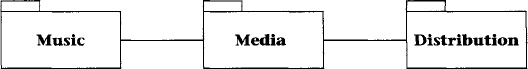
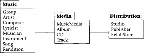
Figure 3.8 Example illustrating classes grouped into packages
If the purpose is to illustrate the relationships of the packages, and the classes are not important at the moment, then it is better to illustrate with the contents elided. Figure 3.7 illustrates the notation with the music industry example at a very high level. Music is created and placed on Media. The Media is then Distributed. There is an association between Music and Media, and between Media and Distribution.
Let us look at the organization of the classes. The music industry is illustrated in Figure 3.8 with the classes listed. The Music package contains classes that are responsible for creating the music. Examples of Groups are the Beatles and the Bangles. Sarah McLachlan and Sting are Artists. Groups and Artists are involved in creating the music. We will look shortly at the other classes and how they are related. The Media package contains classes that physically hold the recordings of the music. The Distribution package contains classes that bring the media to you.

Figure 3.9 Relationships between classes in the music package
The contents of a package can be expanded into greater detail. The relationships of the classes within the Music package are illustrated in Figure 3.9. A Group is an aggregation of two or more Artists. As indicated by the multiplicity between Artist and Group, [0 .. *], an Artist may or may not be in a Group, and may be in more than one Group. Composers, Lyricists, and Musicians are different types of Artists. A Song is associated with one or more Composers. A Song may not have any Lyricist, or any number of Lyricists. A Song may have any number of Renditions. A Rendition is associated with exactly one Song. A Rendition is associated with Musicians and Instruments. A given Musician-Instrument combination is associated with any number of Renditions. A specific Rendition-Musician combination may be associated with any number of Instruments. A given Rendition-Instrument combination is associated with any number of Musicians.
A system can be understood more easily by shifting focus to each package in turn. We turn our attention now to the classes and relationships in the Media package, shown in Figure 3.10. The associated classes from the Music and Distribution packages are also shown, detailing how the Media package is related to the other two packages. The Music Media is associated with the Group and Artist classes, which are contained in the Music package shown in Figure 3.8. The Music Media is also associated with the Publisher, Studio, and Producer classes, which are contained in the Distribution package shown in Figure 3.8. Albums and CDs are types of Music Media. Albums and CDs are both composed of Tracks. Tracks are associated with Renditions.

Figure 3.10 Classes of the media package and related classes
3.2 Activity Diagrams
UML has a full suite of diagram types, each of which fulfills a need for describing a view of the design. UML activity diagrams are used to specify the activities and the flow of control in a process. The process may be a workflow followed by people, organizations, or other physical things. Alternatively, the process may be an algorithm implemented in software. The syntax and the semantics of the UML constructs are the same, regardless of the process described. Our examples draw from workflows that are followed by people and organizations, since these are more useful for the logical design of databases.
3.2.1 Activity Diagram Notation Description
Activity diagrams include notation for nodes, control flow, and organization. The icons we are describing here are outlined in Figure 3.11. The notation is further clarified by example in Section 3.2.2.
The nodes include initial node, final node, and activity node. Any process begins with control residing in the initial node, represented as a solid black circle. The process terminates when control reaches a final node, represented as a solid black circle surrounded by a concentric circle (i.e., a bull’s-eye). Activity nodes are states where specified work is processed. For example, an activity might be named “Generate quote.” The name of an activity is typically a descriptive verb or short verb phrase, written inside a lozenge shape. Control resides in an activity until that activity is completed. Then control follows the outgoing flow.
Control flow icons include flows, decisions, forks, and joins. A flow is drawn with an arrow. Control flows in the direction of the arrow. Decision nodes are drawn as a hollow diamond with multiple outgoing flows. Each flow from a decision node must have a guard condition. A guard condition is written in brackets next to the flow. Control flows in exactly one direction from a decision node, and only follows a flow if the guard condition is true. The guard conditions associated with a decision node must be mutually exclusive, to avoid nondeterministic behavior. There can be no ambiguity as to which direction the control flows. The guards must cover all possible test conditions, so that control is not blocked at the decision node. One path may be guarded with [else]. If a path is guarded by [else], then control flows in that direction only if all the other guards fail. Forks and joins are both forms of synchronization written with a solid bar. The fork has one incoming flow and multiple outgoing flows. When control flows to a fork, the control concurrently follows all the outgoing flows. These are referred to as concurrent threads. Joins are the opposite of forks; the join construct has multiple incoming flows and one outgoing flow. Control flows from a join only when control has reached the join from each of the incoming flows.

Figure 3.11 UML activity diagram constructs
Activity diagrams may be further organized using partitions, also known as swim lanes. Partitions split activities into subsets, organized by responsible party. Each subset is named and enclosed with lines.
3.2.2 Activity Diagrams for Workflow
Figure 3.12 illustrates the UML activity diagram constructs used for the publication of this book. This diagram is partitioned into two subsets of activities, organized by responsible party: the left subset contains Customer activities, and the right subset contains Manufacturer activities. Activity partitions are sometimes called swim lanes, because of their typical appearance. Activity partitions may be arranged vertically, horizontally, or in a grid. Curved dividers may be used, although this is atypical. Activity diagrams can also be written without a partition. The construct is organizational, and doesn’t carry inherent semantics. The meaning is suggested by your choice of subset names.
Control begins in the initial state, represented by the solid dot in the upper-left corner of Figure 3.12. Control flows to the first activity, where the customer requests a quote (Request quote). Control remains in an activity until that activity is completed; then the control follows the outgoing arrow. When the request for a quote is complete, the Manufacturer generates a quote (Generate quote). Then the Customer reviews the quote (Review quote).
The next construct is a branch, represented by a diamond. Each outgoing arrow from a branch has a guard. The guard represents a condition that must be true in order for control to flow along that path. Guards are written as short condition descriptions enclosed in brackets. After the Customer finishes reviewing the quote in Figure 3.12, if it is unacceptable the process reaches a final state and terminates. A final state is represented with a target (the bull’s-eye). If the quote is acceptable, then the Customer places an order (Place order). The Manufacturer enters (Enter order), produces (Produce order), and ships the order (Ship order).
At a fork, control splits into multiple concurrent threads. The notation is a solid bar with one incoming arrow and multiple outgoing arrows. After the order ships in Figure 3.12, control reaches a fork and splits into two threads. The Customer receives the order (Receive order). In parallel to the Customer receiving the order, the Manufacturer generates an invoice (Generate invoice), and then the Customer receives the invoice (Receive invoice). Order of activities between threads is not constrained. Thus, the Customer may receive the order before or after the manufacturer generates the invoice, or even after the Customer receives the invoice.

Figure 3.12 UML activity diagram, manufacturing example.
At a join, multiple threads merge into a single thread. The notation is a solid bar with multiple incoming arrows and one outgoing arrow. In Figure 3.12, after the Customer receives the order and the invoice, then the Customer will pay (Pay). All incoming threads must complete before control continues along the outgoing arrow.
Finally, in Figure 3.12, the Customer pays, the Manufacturer records the payment (Record payment), and then a final state is reached. Notice that an activity diagram may have multiple final states. However, there can only be one initial state.
There are at least two uses for activity diagrams in the context of database design. Activity diagrams can specify the interactions of classes in a database schema. Class diagrams capture structure, activity diagrams capture behavior. The two types of diagrams can present complementary aspects of the same system. For example, one can easily imagine that Figure 3.12 illustrates the usage of classes named Quote, Order, Invoice, and Payment. Another use for activity diagrams in the context of database design is to illustrate processes surrounding the database. For example, database life cycles can be illustrated using activity diagrams.
3.3 Rules of Thumb for UML Usage
3.4 Summary
The Unified Modeling Language (UML) is a graphical language that is currently very popular for communicating design specifications for software and in particular for logical database designs via class diagrams. The similarity between UML and the ER model is shown through some common examples, including ternary relationships and generalization. UML activity diagrams are used to specify the activities and flow of control in processes. Use of UML in logical database design is summarized with five basic rules of thumb.
3.5 Literature Summary
The definitive reference manual for UML is Rumbaugh, Jacobson, and Booch [2005]. Use Mullins [1999] for more detailed UML database modeling. Other useful UML texts are Naiburg and Maksimchuk [2001], Quatrani [2002], and Rumbaugh, Jacobson, and Booch [2004].