
5 Transforming the Conceptual Data Model to SQL
This chapter focuses on the database life cycle step that is of particular interest when designing relational databases: transformation of the conceptual data model to candidate tables and their definition in SQL [step II(c)]. There is a natural evolution from the ER and UML data models to a relational schema. The evolution is so natural, in fact, that it supports the contention that conceptual data modeling is an effective early step in relational database development. This contention has been proven to some extent by the widespread commercialization and use of software design tools that support not only conceptual data modeling but also the automatic conversion of these models to vendor-specific SQL table definitions and integrity constraints.
In this chapter we assume the applications to be Online Transaction Processing (OLTP). Note that Online Analytical Processing (OLAP) applications are the subject of Chapter 8.
5.1 Transformation Rules and SQL Constructs
Let’s first look at the ER and UML modeling constructs in detail to see how the rules about transforming the conceptual data model to SQL tables are defined and applied. Our example is drawn from the company personnel and project conceptual schemas illustrated in Figure 4.3 (see Chapter 4).
The basic transformations can be described in terms of the three types of tables they produce:
- SQL table with the same information content as the original entity from which it is derived. This transformation always occurs for entities with binary relationships (associations) that are many-to-many, one-to-many on the “one” (parent) side, or one-to-one on either side; entities with binary recursive relationships that are many-to-many; and entities with any ternary or higher-degree relationship or a generalization hierarchy.
- SQL table with the embedded foreign key of the parent entity. This transformation always occurs for entities with binary relationships that are one-to-many for the entity on the “many” (child) side, for one-to-one relationships for one of the entities, and for each entity with a binary recursive relationship that is one-to-one or one-to-many. This is one of the two most common ways design tools handle relationships, by prompting the user to define a foreign key in the child table that matches a primary key in the parent table.
- SQL table derived from a relationship, containing the foreign keys of all the entities in the relationship. This transformation always occurs for relationships that are binary and many-to-many, relationships that are binary recursive and many-to-many, and all relationships that are of ternary or higher degree. This is the other most common way design tools handle relationships in the ER and UML models. A many-to-many relationship can only be defined in terms of a table that contains foreign keys that match the primary keys of the two associated entities. This new table may also contain attributes of the original relationship—for example, a relationship “enrolled-in” between two entities Student and Course might have the attributes “term” and “grade,” which are associated with a particular enrollment of a student in a particular course.
The following rules apply to handling SQL null values in these transformations:
- Nulls are allowed in an SQL table for foreign keys of associated (referenced) optional entities.
- Nulls are not allowed in an SQL table for foreign keys of associated (referenced) mandatory entities.
- Nulls are not allowed for any key in an SQL table derived from a many-to-many relationship, because only complete row entries are meaningful in the table.
Figures 5.1 through 5.8 show the SQL create table statements that can be derived from each type of ER or UML model construct. Note that table names are shown in boldface for readability. Note also that in each SQL table definition, the term “primary key” represents the key of the table that is to be used for indexing and searching for data.
5.1.1 Binary Relationships
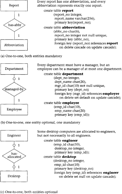
A one-to-one binary relationship between two entities is illustrated in Figure 5.1, parts a through c. Note that the UML equivalent binary association is given in Figure 5.2, parts a through c.
When both entities are mandatory (Figure 5.1a), each entity becomes a table, and the key of either entity can appear in the other entity’s table as a foreign key. One of the entities in an optional relationship (see Department in Figure 5.1b) should contain the foreign key of the other entity in its transformed table. Employee, the other entity in Figure 5.1b, could also contain a foreign key (dept_no) with nulls allowed, but this would require more storage space because of the much greater number of Employee entity instances than Department instances. When both entities are optional (Figure 5.1c), either entity can contain the embedded foreign key of the other entity, with nulls allowed in the foreign keys.
The one-to-many relationship can be shown as either mandatory or optional on the “many” side, without affecting the transformation. On the “one” side it may be either mandatory (Figure 5.1d) or optional (Figure 5.1e). In all cases the foreign key must appear on the “many” side, which represents the child entity, with nulls allowed for foreign keys only in the optional “one” case. Foreign key constraints are set according to the specific meaning of the relationship and may vary from one relationship to another.
The many-to-many relationship, shown in Figure 5.1f as optional for both entities, requires a new table containing the primary keys of both entities. The same transformation applies to either the optional or mandatory case, including the fact that the not null clause must appear for the foreign keys in both cases. Note also that an optional entity means that the SQL table derived from it may have zero rows for that particular relationship. This does not affect “null” or “not null” in the table definition.


5.1.2 Binary Recursive Relationships
A single entity with a one-to-one relationship implies some form of entity occurrence pairing, as indicated by the relationship name. This pairing may be completely optional, completely mandatory, or neither. In all of these cases (Figure 5.3a for ER and Figure 5.4a for UML), the pairing entity key appears as a foreign key in the resulting table. The two key attributes are taken from the same domain but are given different names to designate their unique use. The one-to-many relationship requires a foreign key in the resulting table (Figure 5.3b). The foreign key constraints can vary with the particular relationship.
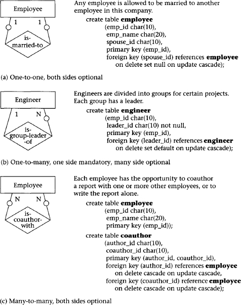
Figure 5.3 ER model: binary recursive relationship
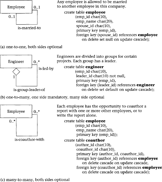
Figure 5.4 UML: binary recursive relationship
The many-to-many relationship is shown as optional (Figure 5.3c) and results in a new table; it could also be defined as mandatory (using the word “must” instead of “may”); both cases have the foreign keys defined as “not null.” In many-to-many relationships, foreign key constraints on delete and update must always be cascade, because each entry in the SQL table depends on the current value or existence of the referenced primary key.
5.1.3 Ternary and n-ary Relationships
An n-ary relationship has (n + 1) possible variations of connectivity: all n sides with connectivity “one;” (n – 1) sides with connectivity “one,” and one side with connectivity “many;” (n – 2) sides with connectivity “one” and two sides with “many;” and so on until all sides are “many.”
The four possible varieties of a ternary relationship are shown in Figure 5.5 for the ER model and Figure 5.6 for UML. All variations are transformed by creating an SQL table containing the primary keys of all entities; however, in each case the meaning of the keys is different. When all three relationships are “one” (Figure 5.5a), the resulting SQL table consists of three possible distinct keys. This arrangement represents the fact that three FDs are needed to describe this relationship. The optionality constraint is not used here because all n entities must participate in every instance of the relationship to satisfy the FD constraints. (See Chapter 6 for more discussion of functional dependencies.)
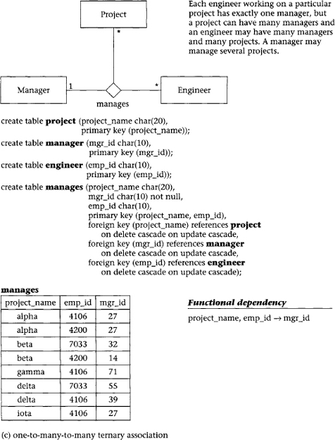
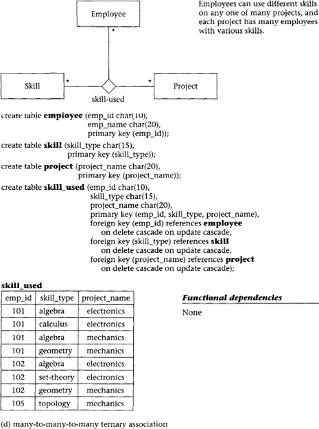
In general the number of entities with connectivity “one” determines the lower bound on the number of FDs. Thus, in Figure 5.3b, which is one-to-one-to-many, there are two FDs; in Figure 5.5c, which is one-to-many-to-many, there is only one FD. When all relationships are “many” (Figure 5.5d), the relationship table is all one composite key, unless the relationship has its own attributes. In that case the key is the composite of all three keys from the three associated entities.
Foreign key constraints on delete and update for ternary relationships transformed to SQL tables must always be cascade, because each entry in the SQL table depends on the current value of, or existence of, the referenced primary key.


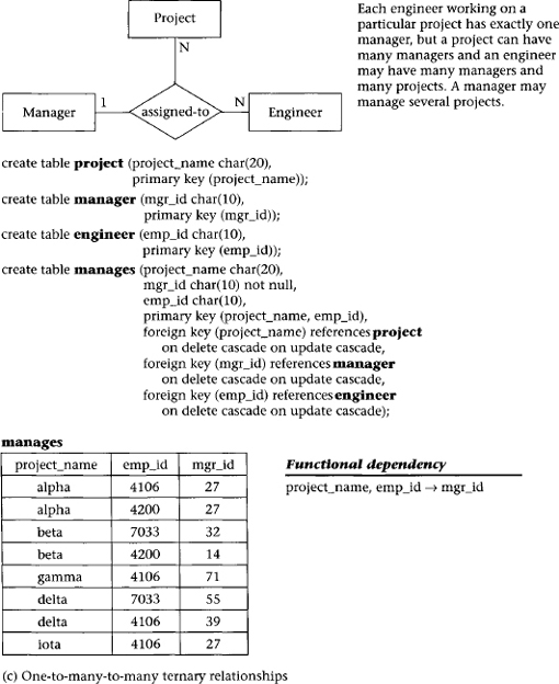

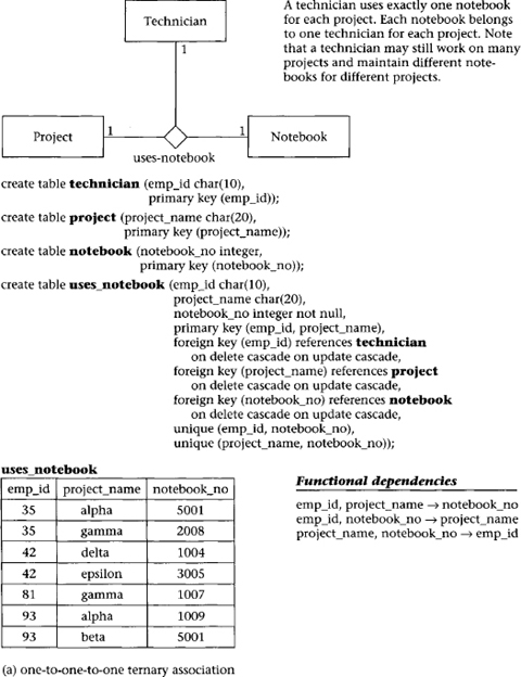
Figure 5.6 UML: ternary and n-ary relationships

5.1.4 Generalization and Aggregation
The transformation of a generalization abstraction can produce separate SQL tables for the generic or supertype entity and each of the subtypes (Figure 5.7 for the ER model and Figure 5.8 for UML). The table derived from the supertype entity contains the supertype entity key and all common attributes. Each table derived from subtype entities contains the supertype entity key and only the attributes that are specific to that subtype. Update integrity is maintained by requiring all insertions and deletions to occur in both the supertype table and relevant subtype table—that is, the foreign key constraint cascade must be used. If the update is to the primary key of the supertype table, then all subtype tables, as well as the supertype table, must be updated. An update to a nonkey attribute affects either the supertype or one subtype table, but not both. The transformation rules (and integrity rules) are the same for both the disjoint and overlapping subtype generalizations.
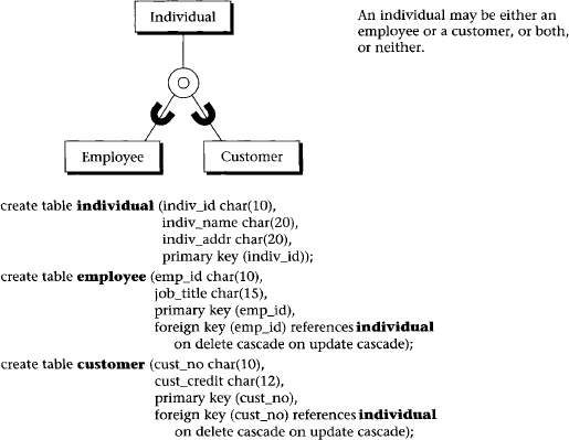

Figure 5.8 UML: generalization and aggregation
Another approach is to have a single table that includes all attributes from the supertype and subtypes (the whole hierarchy in one table), with nulls used when necessary. A third possibility is one table for each subtype, pushing down the common attributes into the specific subtypes. There are advantages and disadvantages to each of these three approaches. Several software tools now support all three options [Fowler 2003; Ambler, 2003].
Database practitioners often add a discriminator to the supertype when they implement generalization. The discriminator is an attribute that has a separate value for each subtype and indicates which subtype to use to get further information. This approach works, up to a point. However, there are situations requiring multiple levels of supertypes and subtypes, where more than one discriminator may be required.
The transformation of an aggregation abstraction also produces a separate table for the supertype entity and each subtype entity. However, there are no common attributes and no integrity constraints to maintain. The main function of aggregation is to provide an abstraction to aid the view integration process. In UML, aggregation is a composition relationship, not a type relationship, which corresponds to a weak entity [Muller, 1999].
5.1.5 Multiple Relationships
Multiple relationships among n entities are always considered to be completely independent. One-to-one, one-to-many binary, or binary recursive relationships resulting in tables that are either equivalent or differ only in the addition of a foreign key can simply be merged into a single table containing all the foreign keys. Many-to-many or ternary relationships that result in SQL tables tend to be unique and cannot be merged.
5.1.6 Weak Entities
Weak entities differ from entities only in their need for keys from other entities to establish their uniqueness. Otherwise, they have the same transformation properties as entities, and no special rules are needed. When a weak entity is already derived from two or more entities in the ER diagram, it can be directly transformed into a table without further change.
5.2 Transformation Steps
The following list summarizes the basic transformation steps from an ER diagram to SQL tables:
- Transform each entity into a table containing the key and nonkey attributes of the entity
- Transform every many-to-many binary or binary recursive relationship into a table with the keys of the entities and the attributes of the relationship
- Transform every ternary or higher-level n-ary relationship into a table
Now let us study each step in turn.
5.2.1 Entity Transformation
If there is a one-to-many relationship between two entities, add the key of the entity on the “one” side (the parent) into the child table as a foreign key. If there is a one-to-one relationship between one entity and another entity, add the key of one of the entities into the table for the other entity, thus changing it to a foreign key. The addition of a foreign key due to a one-to-one relationship can be made in either direction. One strategy is to maintain the most natural parent-child relationship by putting the parent key into the child table. Another strategy is based on efficiency: add the foreign key to the table with fewer rows.
Every entity in a generalization hierarchy is transformed into a table. Each of these tables contains the key of the supertype entity; in reality, the subtype primary keys are foreign keys as well. The supertype table also contains nonkey values that are common to all the relevant entities; the other tables contain nonkey values specific to each subtype entity.
SQL constructs for these transformations may include constraints for not null, unique, and foreign key. A primary key must be specified for each table, either explicitly from among the keys in the ER diagram or by taking the composite of all attributes as the default key. Note that the primary key designation implies that the attribute is not null or unique. It is important to note, however, that not all DBMSs follow the ANSI standard in this regard—it may be possible in some systems to create a primary key that can be null. We recommend that you specify “not null” explicitly for all key attributes.
5.2.2 Many-to-Many Binary Relationship Transformation
In this step, every many-to-many binary relationship is transformed into a table containing the keys of the entities and the attributes of the relationship. The resulting table will show the correspondence between specific instances of one entity and those of another entity. Any attribute of this correspondence, such as the elected office an engineer has in a professional association (Figure 5.1f), is considered intersection data and is added to the table as a nonkey attribute.
SQL constructs for this transformation may include constraints for not null. The unique constraint is not used here because all keys are composites of the participating primary keys of the associated entities in the relationship. The constraints for primary key and foreign key are required, because a table is defined as containing a composite of the primary keys of the associated entities.
5.2.3 Ternary Relationship Transformation
In this step, every ternary (or higher n-ary) relationship is transformed into a table. Ternary or higher n-ary relationships are defined as a collection of the n primary keys in the associated entities in that relationship, with possibly some nonkey attributes that are dependent on the key formed by the composite of those n primary keys.
SQL constructs for this transformation must include constraints for not null, since optionality is not allowed. The unique constraint is not used for individual attributes, because all keys are composites of the participating primary keys of the associated entities in the relationship. The constraints for primary key and foreign key are required because a table is defined as a composite of the primary keys of the associated entities. The unique clause must also be used to define alternate keys that often occur with ternary relationships. Note that a table derived from an n-ary relationship has n foreign keys.
5.2.4 Example of ER-to-SQL Transformation
ER diagrams for the company personnel and project database (Chapter 4) can be transformed to SQL tables. A summary of the transformation of entities and relationships to SQL tables is illustrated in the following list.
SQL tables derived directly from entities (see Figure 4.3d):
| division | secretary | project |
| department | engineer | location |
| employee | technician | prof_assoc |
| manager | skill | desktop |
SQL tables derived from many-to-many binary or many-to-many binary recursive relationships:
- belongs_to
SQL tables transformed from ternary relationships:
- skill_used
- assigned_to
5.3 Summary
Entities, attributes, and relationships in the ER model and classes, attributes, and associations in UML can be transformed directly into SQL (SQL-99) table definitions with some simple rules. Entities are transformed into tables, with all attributes mapped one-to-one to table attributes. Tables representing entities that are the child (“many” side) of a parent-child (one-to-many or one-to-one) relationship must also include, as a foreign key, the primary key of the parent entity. A many-to-many relationship is transformed into a table that contains the primary keys of the associated entities as its composite primary key; the components of that key are also designated as foreign keys in SQL. A ternary or higher-level n-ary relationship is transformed into a table that contains the primary keys of the associated entities; these keys are designated as foreign keys in SQL. A subset of those keys can be designated as the primary key, depending on the functional dependencies associated with the relationship. Rules for generalization require the inheritance of the primary key from the supertype to the subtype entities when transformed into SQL tables. Optionality constraints in the ER or UML diagrams translate into nulls allowed in the relational model when applied to the “one” side of a relationship. In SQL, the lack of an optionality constraint determines the not null designation in the create table definition.
5.4 Literature Summary
Definition of the basic transformations from the ER model to tables is covered in McGee [1974], Wong and Katz [1979], Sakai [1983], Martin [1983], Hawryszkiewyck [1984], Jajodia and Ng [1984], and for UML in Muller [1999].