
2 The Entity-Relationship Model
This chapter defines all the major entity-relationship (ER) concepts that can be applied to the conceptual data modeling phase of the database life cycle. In Section 2.1, we will look at the simple level of ER modeling described in the original work by Chen and extended by others. The simple form of the ER model is used as the basis for effective communication with the end user about the conceptual database. Section 2.2 presents the more advanced concepts; although they are less generally accepted, they are useful to describe certain semantics that cannot be constructed with the simple model.
2.1 Fundamental ER Constructs
2.1.1 Basic Objects: Entities, Relationships, Attributes
The basic ER model consists of three classes of objects: entities, relationships, and attributes.
Entities
Entities are the principal data objects about which information is to be collected; they usually denote a person, place, thing, or event of informational interest. A particular occurrence of an entity is called an entity instance or sometimes an entity occurrence. In our example, employee, department, division, project, skill, and location are all examples of entities. For easy reference, entity names will henceforth be capitalized throughout this text (e.g., Employee, Department, and so forth). The entity construct is a rectangle as depicted in Figure 2.1. The entity name is written inside the rectangle.
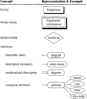
Figure 2.1 The basic ER model
Relationships
Relationships represent real-world associations among one or more entities, and, as such, have no physical or conceptual existence other than that which depends upon their entity associations. Relationships are described in terms of degree, connectivity, and existence. These terms are defined in the sections that follow. The most common meaning associated with the term relationship is indicated by the connectivity between entity occurrences: one-to-one, one-to-many, and many-to-many. The relationship construct is a diamond that connects the associated entities, as shown in Figure 2.1. The relationship name can be written inside or just outside the diamond.
A role is the name of one end of a relationship when each end needs a distinct name for clarity of the relationship. In most of the examples given in Figure 2.2, role names are not required because the entity names combined with the relationship name clearly define the individual roles of each entity in the relationship. However, in some cases role names should be used to clarify ambiguities. For example, in the first case in Figure 2.2, the recursive binary relationship “manages” uses two roles, “manager” and “subordinate,” to associate the proper connectivities with the two different roles of the single entity. Role names are typically nouns. In this diagram, one employee’s role is to be the “manager” of up to n other employees. The other role is for particular “subordinates” to be managed by exactly one other employee.
Attributes
Attributes are characteristics of entities that provide descriptive detail about them. A particular occurrence of an attribute within an entity or relationship is called an attribute value. Attributes of an entity such as Employee may include emp-id, emp-name, emp-address, phone-no, fax-no, job-title, and so on. The attribute construct is an ellipse with the attribute name inside (or an oblong, as shown in Figure 2.1). The attribute is connected to the entity it characterizes.
There are two types of attributes: identifiers and descriptors. An identifier (or key) is used to uniquely determine an instance of an entity; a descriptor (or nonkey attribute) is used to specify a nonunique characteristic of a particular entity instance. Both identifiers and descriptors may consist of either a single attribute or some composite of attributes. For example, an identifier or key of Employee is emp-id, and a descriptor of Employee is emp-name or job-title. Key attributes are underlined in the ER diagram, as shown in Figure 2.1. We note, briefly, that you can have more than one identifier (key) for an entity, or you can have a set of attributes that compose a key (see Section 6.1.2).
Some attributes, such as specialty-area, may be multivalued. The notation for multivalued attributes is a double attachment line, as shown in Figure 2.1. Other attributes may be complex, such as an address that further subdivides into street, city, state, and zip code. Complex attributes are constructed to have attributes of their own; sometimes, however, the individual parts of a complex attribute are specified as individual attributes in the first place. Either form is reasonable in ER notation.
Entities have internal identifiers that uniquely determine the existence of entity instances, but weak entities derive their identity from the identifying attributes of one or more “parent” entities. Weak entities are often depicted with a double-bordered rectangle (see Figure 2.1), which denotes that all occurrences of that entity depend on an associated (strong) entity for their existence in the database. For example, in Figure 2.1, the weak entity Employee-job-history is related to the entity Employee and dependent upon Employee for its own existence.
2.1.2 Degree of a Relationship
The degree of a relationship is the number of entities associated in the relationship. Binary and ternary relationships are special cases where the degrees are 2 and 3, respectively. An n-ary relationship is the general form for any degree n. The notation for degree is illustrated in Figure 2.2. The binary relationship, an association between two entities, is by far the most common type in the natural world. In fact, many modeling systems use only this type. In Figure 2.2, we see many examples of the association of two entities in different ways: Department and Division, Department and Employee, Employee and Project, and so on. A binary recursive relationship (for example, “manages” in Figure 2.2) relates a particular Employee to another Employee by management. It is called recursive because the entity relates only to another instance of its own type. The binary recursive relationship construct is a diamond with both connections to the same entity.
A ternary relationship is an association among three entities. This type of relationship is required when binary relationships are not sufficient to accurately describe the semantics of the association. The ternary relationship construct is a single diamond connected to three entities, as shown in Figure 2.2. Sometimes a relationship is mistakenly modeled as ternary when it could be decomposed into two or three equivalent binary relationships. When this occurs, the ternary relationship should be eliminated to achieve both simplicity and semantic purity. Ternary relationships are discussed in greater detail in Section 2.2.3 and Chapter 6.
An entity may be involved in any number of relationships, and each relationship may be of any degree. Furthermore, two entities may have any number of binary relationships between them, and so on for any n entities (see n-ary relationships defined in Section 2.2.4).

Figure 2.2 Degrees, connectivity, and attributes of a relationship
2.1.3 Connectivity of a Relationship
The connectivity of a relationship describes a constraint on the connection of the associated entity occurrences in the relationship. Values for connectivity are either “one” or “many.” For a relationship between the entities Department and Employee, a connectivity of one for Department and many for Employee means that there is at most one entity occurrence of Department associated with many occurrences of Employee. The actual count of elements associated with the connectivity is called the cardinality of the relationship connectivity; it is used much less frequently than the connectivity constraint because the actual values are usually variable across instances of relationships. Note that there are no standard terms for the connectivity concept, so the reader is admonished to consider the definition of these terms carefully when using a particular database design methodology.
Figure 2.2 shows the basic constructs for connectivity for binary relationships: one-to-one, one-to-many, and many-to-many. On the “one” side, the number one is shown on the connection between the relationship and one of the entities, and on the “many” side, the letter N is used on the connection between the relationship and the entity to designate the concept of many.
In the one-to-one case, the entity Department is managed by exactly one Employee, and each Employee manages exactly one Department. Therefore, the minimum and maximum connectivities on the “is-managed-by” relationship are exactly one for both Department and Employee.
In the one-to-many case, the entity Department is associated with (“has”) many Employees. The maximum connectivity is given on the Employee (many) side as the unknown value N, but the minimum connectivity is known as one. On the Department side the minimum and maximum connectivities are both one, that is, each Employee works within exactly one Department.
In the many-to-many case, a particular Employee may work on many Projects and each Project may have many Employees. We see that the maximum connectivity for Employee and Project is ? in both directions, and the minimum connectivities are each defined (implied) as one.
Some situations, though rare, are such that the actual maximum connectivity is known. For example, a professional basketball team may be limited by conference rules to 12 players. In such a case, the number 12 could be placed next to an entity called “team members” on the many side of a relationship with an entity “team.” Most situations, however, have variable connectivity on the many side, as shown in all the examples of Figure 2.2.
2.1.4 Attributes of a Relationship
Attributes can be assigned to certain types of relationships as well as to entities. An attribute of a many-to-many relationship, such as the “works-on” relationship between the entities Employee and Project (Figure 2.2), could be “task-assignment” or “start-date.” In this case, a given task assignment or start date only has meaning when it is common to an instance of the assignment of a particular Employee to a particular Project via the relationship “works-on.”
Attributes of relationships are typically assigned only to binary many-to-many relationships and to ternary relationships. They are not normally assigned to one-to-one or one-to-many relationships, because of potential ambiguities. For example, in the one-to-one binary relationship “is-managed-by” between Department and Employee, an attribute “start-date” could be applied to Department to designate the start date for that department. Alternatively, it could be applied to Employee as an attribute for each Employee instance, to designate the employee’s start date as the manager of that department. If, instead, the relationship is many-to-many, so that an employee can manage many departments over time, then the attribute “start-date” must shift to the relationship, so each instance of the relationship that matches one employee with one department can have a unique start date for that employee as manager of that department.
2.1.5 Existence of an Entity in a Relationship
Existence of an entity occurrence in a relationship is defined as either mandatory or optional. If an occurrence of either the “one” or “many” side entity must always exist for the entity to be included in the relationship, then it is mandatory. When an occurrence of that entity need not always exist, it is considered optional. For example, in Figure 2.2 the entity Employee may or may not be the manager of any Department, thus making the entity Department in the “is-managed-by” relationship between Employee and Department optional.
Optional existence, defined by a zero on the connection line between an entity and a relationship, defines a minimum connectivity of zero. Mandatory existence defines a minimum connectivity of one. When existence is unknown, we assume the minimum connectivity is one (that is, mandatory).
Maximum connectivities are defined explicitly on the ER diagram as a constant (if a number is shown on the ER diagram next to an entity) or a variable (by default if no number is shown on the ER diagram next to an entity). For example, in Figure 2.2, the relationship “is-occupied-by” between the entity Office and Employee implies that an Office may house from zero to some variable maximum (N) number of Employees, but an Employee must be housed in exactly one Office, that is, mandatory.
Existence is often implicit in the real world. For example, an entity Employee associated with a dependent (weak) entity, Dependent, cannot be optional, but the weak entity is usually optional. Using the concept of optional existence, an entity instance may be able to exist in other relationships even though it is not participating in this particular relationship.
The term existence is also associated with identification of a data object. Many DBMSs provide unique identifiers for rows (Oracle ROW-IDs, for example). Identifying an object such as a row can be done in an existence-based way. It can also be done in a value-based way by identifying the object (row) with the values of one or more attributes or columns of the table.
2.1.6 Alternative Conceptual Data Modeling Notations
At this point we need to digress briefly to look at other conceptual data modeling notations that are commonly used today and compare them with the Chen approach. A popular alternative form for one-to-many and many-to-many relationships uses “crow’s-foot” notation for the “many” side (see Figure 2.3a). This form is used by some CASE tools, such as Knowledgeware’s Information Engineering Workbench (IEW). Relationships have no explicit construct but are implied by the connection line between entities and a relationship name on the connection line. Minimum connectivity is specified by either a 0 (for zero) or perpendicular line (for one) on the connection lines between entities. The term intersection entity is used to designate a weak entity, especially an entity that is equivalent to a many-to-many relationship. Another popular form used today is the IDEFIX notation [IDEF1X, 2005], conceived by Robert G. Brown [Bruce, 1992]. The similarities with the Chen notation are obvious in Figure 2.3b. Fortunately, any of these forms is reasonably easy to learn and read, and their equivalence with the basic ER concepts is obvious from the diagrams. Without a clear standard for the ER model, however, many other constructs are being used today in addition to the three types shown here.


2.2 Advanced ER Constructs
2.2.1 Generalization: Supertypes and Subtypes
The original ER model has been effectively used for communicating fundamental data and relationship definitions with the end user for a long time. However, using it to develop and integrate conceptual models with different end user views was severely limited until it could be extended to include database abstraction concepts such as generalization. The generalization relationship specifies that several types of entities with certain common attributes can be generalized into a higher-level entity type—a generic or superclass entity, more commonly known as a supertype entity. The lower levels of entities—subtypes in a generalization hierarchy—can be either disjoint or overlapping subsets of the supertype entity. As an example, in Figure 2.4 the entity Employee is a higher-level abstraction of Manager, Engineer, Technician, and Secretary—all of which are disjoint types of Employee. The ER model construct for the generalization abstraction is the connection of a supertype entity with its subtypes, using a circle and the subset symbol on the connecting lines from the circle to the subtype entities. The circle contains a letter specifying a disjointness constraint (see the following discussion). Specialization, the reverse of generalization, is an inversion of the same concept; it indicates that subtypes specialize the supertype.

Figure 2.4 Supertypes and subtypes
A supertype entity in one relationship may be a subtype entity in another relationship. When a structure comprises a combination of supertype/subtype relationships, that structure is called a supertype/subtype hierarchy or generalization hierarchy. Generalization can also be described in terms of inheritance, which specifies that all the attributes of a supertype are propagated down the hierarchy to entities of a lower type. Generalization may occur when a generic entity, which we call the supertype entity, is partitioned by different values of a common attribute. For example, in Figure 2.4 the entity Employee is a generalization of Manager, Engineer, Technician, and Secretary over the attribute “job-title” in Employee.
Generalization can be further classified by two important constraints on the subtype entities: disjointness and completeness. The disjointness constraint requires the subtype entities to be mutually exclusive. We denote this type of constraint by the letter “d” written inside the generalization circle (Figure 2.4a). Subtypes that are not disjoint (i.e., that overlap) are designated by using the letter “o” inside the circle. As an example, the supertype entity Individual has two subtype entities, Employee and Customer; these subtypes could be described as overlapping, or not mutually exclusive (Figure 2.4b). Regardless of whether the subtypes are disjoint or overlapping, they may have additional special attributes in addition to the generic (inherited) attributes from the supertype.
The completeness constraint requires the subtypes to be all-inclusive of the supertype. Thus, subtypes can be defined as either total or partial coverage of the supertype. For example, in a generalization hierarchy with supertype Individual and subtypes Employee and Customer, the subtypes may be described as all-inclusive or total. We denote this type of constraint by a double line between the supertype entity and the circle. This is indicated in Figure 2.4b, which implies that the only types of individuals to be considered in the database are employees and customers.

Figure 2.5 Aggregation
2.2.2 Aggregation
Aggregation is a form of abstraction between a supertype and subtype entity that is significantly different from the generalization abstraction. Generalization is often described in terms of an “is-a” relationship between the subtype and the supertype—for example, an Employee is an Individual. Aggregation, on the other hand, is the relationship between the whole and its parts and is described as a “part-of” relationship—for example, a report and a prototype software package are both parts of a deliverable for a contract. Thus, in Figure 2.5, the entity Software-product is seen to consist of component parts Program and User’s Guide. The construct for aggregation is similar to generalization, in that the supertype entity is connected with the subtype entities with a circle; in this case, the letter “A” is shown in the circle. However, there are no subset symbols because the “part-of” relationship is not a subset. Furthermore, there are no inherited attributes in aggregation; each entity has its own unique set of attributes.
2.2.3 Ternary Relationships
Ternary relationships are required when binary relationships are not sufficient to accurately describe the semantics of an association among three entities. Ternary relationships are somewhat more complex than binary relationships, however. The ER notation for a ternary relationship is shown in Figure 2.6 with three entities attached to a single relationship diamond, and the connectivity of each entity is designated as either “one” or “many.” An entity in a ternary relationship is considered to be “one” if only one instance of it can be associated with one instance of each of the other two associated entities. It is “many” if more than one instance of it can be associated with one instance of each of the other two associated entities. In either case, it is assumed that one instance of each of the other entities is given.
As an example, the relationship “manages” in Figure 2.6c associates the entities Manager, Engineer, and Project. The entities Engineer and Project are considered “many;” the entity Manager is considered “one.” This is represented by the following assertions.
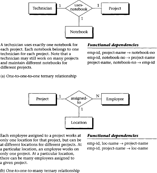

Figure 2.6 Ternary relationships
- Assertion 1: One engineer, working under one manager, could be working on many projects.
- Assertion 2: One project, under the direction of one manager, could have many engineers.
- Assertion 3: One engineer, working on one project, must have only a single manager
Assertion 3 could also be written in another form, using an arrow (->) in a kind of shorthand called a functional dependency. For example:
emp-id, project-name -> mgr-id
where emp-id is the key (unique identifier) associated with the entity Engineer, project-name is the key associated with the entity Project, and mgr-id is the key of the entity Manager. In general, for an n-ary relationship, each entity considered to be a “one” has its key appearing on the right side of exactly one functional dependency (FD). No entity considered “many” ever has its key appear on the right side of an FD.
All four forms of ternary relationships are illustrated in Figure 2.6. In each case, the number of “one” entities implies the number of FDs used to define the relationship semantics, and the key of each “one” entity appears on the right side of exactly one FD for that relationship.
Ternary relationships can have attributes in the same way that many-to-many binary relationships can. The values of these attributes are uniquely determined by some combination of the keys of the entities associated with the relationship. For example, in Figure 2.6d the relationship “skill-used” might have the attribute “tool” associated with a given employee using a particular skill on a certain project, indicating that a value for tool is uniquely determined by the combination of employee, skill, and project.
2.2.4 General n-ary Relationships
Generalizing the ternary form to higher-degree relationships, an n-ary relationship that describes some association among n entities is represented by a single relationship diamond with n connections, one to each entity (see Figure 2.7). The meaning of this form can best be described in terms of the functional dependencies among the keys of the n associated entities. There can be anywhere from zero to n FDs, depending on the number of “one” entities. The collection of FDs that describe an n-ary relationship must have n components: n – 1 on the left side (determinant) and 1 on the right side. A ternary relationship (n = 3), for example, has two components on the left and one on the right, as we saw in the example in Figure 2.6. In a more complex database, other types of FDs may also exist within an n-ary relationship. When this occurs, the ER model does not provide enough semantics on its own, and it must be supplemented with a narrative description of these dependencies.
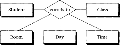
Figure 2.7 n-ary relationships.
2.2.5 Exclusion Constraint
The normal, or default, treatment of multiple relationships is the inclusive OR, which allows any or all of the entities to participate. In some situations, however, multiple relationships may be affected by the exclusive OR (exclusion) constraint, which allows at most one entity instance among several entity types to participate in the relationship with a single root entity. For example, in Figure 2.8, suppose the root entity Worktask has two associated entities, External-project and Internal-project. At most one of the associated entity instances could apply to an instance of Work-task.

Figure 2.8 Exclusion constraint
2.2.6 Referential Integrity
We note that a foreign key is an attribute of a table (not necessarily a key of any kind) that relates to a key in another table. Referential integrity requires that for every foreign key instance that exists in a table, the row (and thus the key instance) of the parent table associated with that foreign key instance must also exist. The referential integrity constraint has become integral to relational database design and is usually implied as requirements for the resulting relational database implementation. (Chapter 5 discusses the SQL implementation of referential integrity constraints.)
2.3 Summary
The basic concepts of the ER model and their constructs are described in this chapter. An entity is a person, place, thing, or event of informational interest. Attributes are objects that provide descriptive information about entities. Attributes may be unique identifiers or nonunique descriptors. Relationships describe the connectivity between entity instances: one-to-one, one-to-many, or many-to-many. The degree of a relationship is the number of associated entities: two (binary), three (ternary), or any n (n-ary). The role (name), or relationship name, defines the function of an entity in a relationship.
The concept of existence in a relationship determines whether an entity instance must exist (mandatory) or not (optional). So, for example, the minimum connectivity of a binary relationship—that is, the number of entity instances on one side that are associated with one instance on the other side—can either be zero, if optional, or one, if mandatory. The concept of generalization allows for the implementation of supertype and subtype abstractions.
The more advanced constructs in ER diagrams are sporadically used and have no generally accepted form as yet. They include ternary relationships, which we define in terms of the FD concept of relational databases; constraints on exclusion; and the implicit constraints from the relational model, such as referential integrity.
2.4 Literature Summary
Most of the notation in this chapter is from Chen’s original ER definition [Chen, 1976]. The concept of data abstraction was first proposed by Smith and Smith [1977] and applied to the ER model by Scheuermann, Scheffner, and Weber [1980], Elmasri and Navathe [2003], Bruce [1992], IDEF1X [2005], among others. The application of the semantic network model to conceptual schema design was shown by Bachman [1977], McKleod and King [1979], Hull and King [1987], and Peckham and Maryanski [1988].