
7 An Example of Logical Database Design
The following example illustrates how to proceed through the requirements analysis and logical design steps of the database life cycle, in a practical way, for a relational database.
7.1 Requirements Specification
The management of a large retail store would like a database to keep track of sales activities. The requirements analysis for this database led to the six entities and their unique identifiers shown in Table 7.1. The following assertions describe the data relationships:
- Each customer has one job title, but different customers may have the same job title.
- Each customer may place many orders, but only one customer may place a particular order.
- Each department has many salespeople, but each salesperson must work in only one department.
- Each department has many items for sale, but each item is sold in only one department. (“Item” means item type, like IBM PC).
- For each order, items ordered in different departments must involve different salespeople, but all items ordered within one department must be handled by exactly one salesperson. In other words, for each order, each item has exactly one salesperson; and for each order, each department has exactly one salesperson.
For physical design (e.g., access methods, etc.) it is necessary to determine what kind of processing needs to be done on the data; that is, what are the queries and updates needed to satisfy the user requirements, and what are their frequencies? In addition, the requirements analysis should determine whether there will be substantial database growth (i.e., volumetrics); in what time frame that growth will take place; and whether the frequency and type of queries and updates will change, as well. Decay as well as growth should be estimated, as each will have significant effect on the later stages of database design.
7.1.1 Design Problems

Table 7.1 Requirements Analysis Results
7.2 Logical Design
Our first step is to develop a conceptual data model diagram and a set of FDs to correspond to each of the assertions given. Figure 7.1 presents the diagram for the ER model, and Figure 7.2 shows the equivalent diagram for UML. Normally, the conceptual data model is developed without knowing all the FDs, but in this example the nonkey attributes are omitted so that the entire database can be represented with only a few statements and FDs. The result of this analysis, relative to each of the assertions given, follows in Table 7.2.
The candidate tables required to represent the semantics of this problem can be derived easily from the constructs for entities and relationships. Primary keys and foreign keys are explicitly defined.
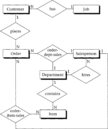

Figure 7.2 Conceptual data model diagram for UML
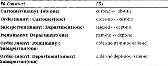
Table 7.2 Results of the Analysis of the Conceptual Data Model
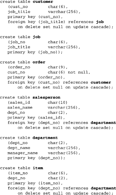

Note that it is often better to put foreign key definitions in separate (alter) statements. This prevents the possibility of getting circular definitions with very large schemas.
This process of decomposition and reduction of tables moves us closer to a minimum set of normalized (BCNF) tables, as shown in Table 7.3.
The reductions shown in this section have decreased storage space and update cost and have maintained the normalization of BCNF (and thus 3NF). On the other hand, we have potentially higher retrieval cost—given the transaction “list all job_titles,” for example—and have increased the potential for loss of integrity because we have eliminated simple tables with only key attributes. Resolution of these trade-offs depends on your priorities for your database.
The details of indexing will be covered in the companion book, Physical Database Design. However, during the logical design phase of defining SQL tables, it makes sense to start considering where to create indexes. At a minimum, all primary keys and all foreign keys should be indexed. Indexes are relatively easy to implement and store, and make a significant difference in reducing the access time to stored data.

Table 7.3 Decomposition and Reduction of Tables
7.3 Summary
In this chapter, we developed a global conceptual schema and a set of SQL tables for a relational database, given the requirements specification for a retail store database. The example illustrates the database life cycle steps of conceptual data modeling, global schema design, transformation to SQL tables, and normalization of those tables. It summarizes the techniques presented in Chapters 1 through 6.