
Some of the subtleties of network programming are difficult to grasp without some understanding of the data structures associated with the socket implementation and certain details of how the underlying protocols work. This is especially true of TCP sockets (i.e., instances of Socket). This chapter describes some of what goes on under the hood when you create and use an instance of Socket or ServerSocket. (The initial discussion and Section 6.5 apply as well to DatagramSocket and MulticastSocket. Also, since each SocketChannel has an underlying Socket (and similarly for the other flavors of channels), the discussion applies to them as well. However, most of this chapter focuses on TCP sockets, that is, Socket and Server-Socket.) Please note that this description covers only the normal sequence of events and glosses over many details. Nevertheless, we believe that even this basic level of understanding is helpful. Readers who want the full story are referred to the TCP specification [15] or to one of the more comprehensive treatises on the subject [5,18].
Figure 6.1 is a simplified view of some of the information associated with a Socket instance. The classes are supported by an underlying implementation that is provided by the JVM and/or the platform on which it is running (i.e., the “socket layer” of the host’s OS). Operations on the Java objects are translated into manipulations of this underlying abstraction. In this chapter, "Socket" refers generically to one of the classes in Figure 6.1, while “socket” refers to the underlying abstraction, whether it is provided by an underlying OS or the JVM implementation itself (e.g., in an embedded system). It is important to note that other (possibly non-Java) programs running on the same host may be using the network via the underlying socket abstraction, and thus competing with Java Socket instances for resources such as ports.

By “socket structure” here we mean the collection of data structures in the underlying implementation (of both the JVM and TCP/IP, but primarily the latter) that contain the information associated with a particular Socket instance. For example, the socket structure contains, among other information
The local and remote Internet addresses and port numbers associated with the socket. The local Internet address (labeled “Local IP” in the figure) is one of those assigned to the local host; the local port is set at
Socketcreation time. The remote address and port identify the remote socket, if any, to which the local socket is connected. We will say more about how and when these values are determined shortly (Section 6.5 contains a concise summary).A FIFO queue of received data waiting to be delivered and a queue for data waiting to be transmitted.
For a TCP socket, additional protocol state information relevant to the opening and closing TCP handshakes. In Figure 6.1, the state is “Closed”; all sockets start out in the Closed state.
Some general-purpose operating systems provide tools that enable users to obtain a “snapshot” of these underlying data structures. One such tool is netstat, which is typically available on both Unix (Linux) and Windows platforms. Given appropriate options, netstat displays exactly the information indicated in Figure 6.1: number of bytes in SendQ and RecvQ, local and remote IP addresses and port numbers, and the connection state. Command-line options may vary, but the output should look something like this:
   Active Internet connections (servers and established)
   Proto Recv-Q Send-Q  Local Address           Foreign Address     State
   tcp        0      0  0.0.0.0:36045           0.0.0.0:*           LISTEN
   tcp        0      0  0.0.0.0:111             0.0.0.0:*           LISTEN
   tcp        0      0  0.0.0.0:53363           0.0.0.0:*           LISTEN
   tcp        0      0  127.0.0.1:25            0.0.0.0:*           LISTEN
   tcp        0      0  128.133.190.219:34077   4.71.104.187:80     TIME_WAIT
   tcp        0      0  128.133.190.219:43346   79.62.132.8:22      ESTABLISHED
   tcp        0      0  128.133.190.219:875     128.133.190.43:2049 ESTABLISHED
   tcp6       0      0  :::22                   :::*                LISTEN
The first four lines and the last line depict server sockets listening for connections. (The last line is a listening socket bound to an IPv6 address.) The fifth line corresponds to a connection to a Web server (port 80) that is partially shut down (see Section 6.4.2 below). The next-to-last two lines are existing TCP connections. You may want to play with netstat, if it is available on your system, to examine the status of connections in the scenarios depicted below. Be aware, however, that because the transitions between states depicted in the figures happen so quickly, it may be difficult to catch them in the “snapshot” provided by netstat.
Knowing that these data structures exist and how they are affected by the underlying protocols is useful because they control various aspects of the behavior of the various Socket objects. For example, because TCP provides a reliable byte-stream service, a copy of any data written to a Socket’s OutputStream must be kept until it has been successfully received at the other end of the connection. Writing data to the output stream does not imply that the data has actually been sent—only that it has been copied into the local buffer. Even flush()ing a Socket’s OutputStream doesn’t guarantee that anything goes over the wire immediately. Moreover, the nature of the byte-stream service means that message boundaries are not preserved in the input stream. As we saw in Section 3.3, this complicates the process of receiving and parsing for some protocols. On the other hand, with a DatagramSocket, packets are not buffered for retransmission, and by the time a call to the send() method returns, the data has been given to the network subsystem for transmission. If the network subsystem cannot handle the message for some reason, the packet is silently dropped (but this is rare).
The next three sections deal with some of the subtleties of sending and receiving with TCP’s byte-stream service. Then, Section 6.4 considers the connection establishment and termination of the TCP protocol. Finally, Section 6.5 discusses the process of matching incoming packets to sockets and the rules about binding to port numbers.
As a programmer, the most important thing to remember when using a TCP socket is this:
You cannot assume any correspondence between writes to the output stream at one end of the connection and reads from the input stream at the other end.
In particular, data passed in a single invocation of the output stream’s write() method at the sender can be spread across multiple invocations of the input stream’s read() method at the other end; and a single read() may return data passed in multiple write()s.
To see this, consider a program that does the following:
   byte[] buffer0 = new byte[1000];
   byte[] buffer1 = new byte[2000];
   byte[] buffer2 = new byte[5000];
   ...
   Socket s = new Socket(destAddr, destPort);
   OutputStream out = s.getOutputStream();
   ...
   out.write(buffer0);
   ...
   out.write(buffer1);
   ...
   out.write(buffer2);
   ...
   s.close();
where the ellipses represent code that sets up the data in the buffers but contains no other calls to out.write(). Throughout this discussion, “in” refers to the InputStream of the receiver’s Socket, and “out” refers to the OutputStream of the sender’s Socket.
This TCP connection transfers 8000 bytes to the receiver. The way these 8000 bytes are grouped for delivery at the receiving end of the connection depends on the timing between the out.write()s and in.read()s at the two ends of the connection—as well as the size of the buffers provided to the in.read() calls.
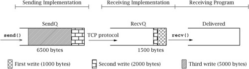
We can think of the sequence of all bytes sent (in one direction) on a TCP connection up to a particular instant in time as being divided into three FIFO queues:
SendQ: Bytes buffered in the underlying implementation at the sender that have been written to the output stream but not yet successfully transmitted to the receiving host.
RecvQ: Bytes buffered in the underlying implementation at the receiver waiting to be delivered to the receiving program—that is, read from the input stream.
Delivered: Bytes already read from the input stream by the receiver.
A call to out.write() at the sender appends bytes to SendQ. The TCP protocol is responsible for moving bytes—in order—from SendQ to RecvQ. It is important to realize that this transfer cannot be controlled or directly observed by the user program, and that it occurs in chunks whose sizes are more or less independent of the size of the buffers passed in write()s. Bytes are moved from RecvQ to Delivered as they are read from the Socket’s InputStream by the receiving program; the size of the transferred chunks depends on the amount of data in RecvQ and the size of the buffer given to read().
Figure 6.2 shows one possible state of the three queues after the three out.write()s in the example above, but before any in.read()s at the other end. The different shading patterns denote bytes passed in the three different invocations of write() shown above.
The output of netstat on the sending host at the instant depicted in Figure 6.2 would contain a line like:
   Active Internet connections
   Proto Recv-Q Send-Q Local Address        Foreign Address   State
   tcp        0   6500 10.21.44.33:43346    192.0.2.8:22      ESTABLISHED
On the receiving host, netstat shows:
   Active Internet connections
   Proto Recv-Q Send-Q Local Address   Foreign Address     State
   tcp     1500      0 192.0.2.8:22    10.21.44.33:43346   ESTABLISHED
Now suppose the receiver calls read() with a byte array of size 2000. The read() call will move all of the 1500 bytes present in the waiting-for-delivery (RecvQ) queue into the byte array and return the value 1500. Note that this data includes bytes passed in both the first and second calls to write(). At some time later, after TCP has completed transfer of more data, the three partitions might be in the state shown in Figure 6.3.

If the receiver now calls read() with a buffer of size 4000, that many bytes will be moved from the waiting-for-delivery (RecvQ) queue to the already-delivered (Delivered) queue; this includes the remaining 1500 bytes from the second write(), plus the first 2500 bytes from the third write(). The resulting state of the queues is shown in Figure 6.4.

The number of bytes returned by the next call to read() depends on the size of the buffer and the timing of the transfer of data over the network from the send-side socket/TCP implementation to the receive-side implementation. The movement of data from the SendQ to the RecvQ buffer has important implications for the design of application protocols. We have already encountered the need to parse messages as they are received via a Socket when in-band delimiters are used for framing (see Section 3.3). In the following sections, we consider two more subtle ramifications.
Application protocols have to be designed with some care to avoid deadlock—that is, a state in which each peer is blocked waiting for the other to do something. For example, it is pretty obvious that if both client and server try to receive immediately after a connection is established, deadlock will result. Deadlock can also occur in less immediate ways.
The buffers SendQ and RecvQ in the implementation have limits on their capacity. Although the actual amount of memory they use may grow and shrink dynamically, a hard limit is necessary to prevent all of the system’s memory from being gobbled up by a single TCP connection under control of a misbehaving program. Because these buffers are finite, they can fill up, and it is this fact, coupled with TCP’s flow control mechanism, that leads to the possibility of another form of deadlock.
Once RecvQ is full, the TCP flow control mechanism kicks in and prevents the transfer of any bytes from the sending host’s SendQ, until space becomes available in RecvQ as a result of the receiver calling the input stream’s read() method. (The purpose of the flow control mechanism is to ensure that the sender does not transmit more data than the receiving system can handle.) A sending program can continue to write output until SendQ is full; however, once SendQ is full, a call to out.write() will block until space becomes available, that is, until some bytes are transferred to the receiving socket’s RecvQ. If RecvQ is also full, everything stops until the receiving program calls in.read() and some bytes are transferred to Delivered.
Let’s assume the sizes of SendQ and RecvQ are SQS and RQS, respectively. A write() call with a byte array of size n such that n > SQS will not return until at least n – SQS bytes have been transferred to RecvQ at the receiving host. If n exceeds (SQS + RQS), write() cannot return until after the receiving program has read at least n − (SQS + RQS) bytes from the input stream. If the receiving program does not call read(), a large send() may not complete successfully. In particular, if both ends of the connection invoke their respective output streams’ write() method simultaneously with buffers greater than SQS + RQS, deadlock will result: neither write will ever complete, and both programs will remain blocked forever.
As a concrete example, consider a connection between a program on Host A and a program on Host B. Assume SQS and RQS are 500 at both A and B. Figure 6.5 shows what happens when both programs try to send 1500 bytes at the same time. The first 500 bytes of data in the program at Host A have been transferred to the other end; another 500 bytes have been copied into SendQ at Host A. The remaining 500 bytes cannot be sent—and therefore out.write() will not return—until space frees up in RecvQ at Host B. Unfortunately, the same situation holds in the program at Host B. Therefore, neither program’s write() call will ever complete.

Figure 6.5. Deadlock due to simultaneous write()s to output streams at opposite ends of the connection.
The moral of the story: Design the protocol carefully to avoid sending large quantities of data simultaneously in both directions.
Can this really happen? Let’s review the compression protocol example in Section 4.5. Try running the compression client with a large file that is still large after compression. The precise definition of “large” here depends on your system, but a file that is already compressed and exceeds 2MB should do nicely. For each read/write, the compression client prints an “R”/“W” to the console. If both the uncompressed and compressed versions of the file are large enough, your client will print a series of Ws and then stop without terminating or printing any Rs.
Why does this happen? The program CompressClient.java sends all of the uncompressed data to the compression server before it attempts to read anything from the compressed stream. The server, on the other hand, simply reads the uncompressed byte sequence and writes the compressed sequence back to the client. (The number of bytes the server reads before it writes some compressed data depends on the compression algorithm it uses.) Consider the case where SendQ and RecvQ for both client and server hold 500 bytes each and the client sends a 10,000-byte (uncompressed) file. Suppose also that for this file the server reads about 1000 bytes and then writes 500 bytes, for a 2:1 compression ratio. After the client sends 2000 bytes, the server will eventually have read them all and sent back 1000 bytes, and the client’s RecvQ and the server’s SendQ will both be full. After the client sends another 1000 bytes and the server reads them, the server’s subsequent attempt to write will block. When the client sends the next 1000 bytes, the client’s SendQ and the server’s RecvQ will both fill up. The next client write will block, creating deadlock.
How do we solve this problem? One solution is to execute the client writing and reading loop in separate threads. One thread repeatedly reads uncompressed bytes from a file and sends them to the server until the end of the file is reached, whereupon it calls shutdownOutput() on the socket. The other thread repeatedly reads compressed bytes from the input stream connected to the server and writes them to the output file, until the input stream ends (i.e., the server closes the socket). When one thread blocks, the other thread can proceed independently. We can easily modify our client to follow this approach by putting the call to SendBytes() in CompressClient.java inside a thread as follows:
   Thread thread = new Thread() {
     public void run() {
       try {
         SendBytes(sock, fileIn);
       } catch (Exception ignored) {}
     }
   };
   thread.start();
See CompressClientNoDeadlock.java on the book’s Web site for the complete example.
Of course, the problem can also be solved without using threads, through the use of nonblocking Channels and Selectors, as described in Chapter 5.
The TCP implementation’s need to copy user data into SendQ for potential retransmission also has implications for performance. In particular, the sizes of the SendQ and RecvQ buffers affect the throughput achievable over a TCP connection. Throughput refers to the rate at which bytes of user data from the sender are made available to the receiving program; in programs that transfer a large amount of data, we want to maximize this rate. In the absence of network capacity or other limitations, bigger buffers generally result in higher throughput.
The reason for this has to do with the cost of transferring data into and out of the buffers in the underlying implementation. If you want to transfer n bytes of data (where n is large), it is generally much more efficient to call write() once with a buffer of size n than it is to call it n times with a single byte.[1] However, if you call write() with a size parameter that is much larger than SQS (the size of SendQ), the system has to transfer the data from the user address space in SQS-sized chunks. That is, the socket implementation fills up the SendQ buffer, waits for data to be transferred out of it by the TCP protocol, refills SendQ, waits some more, and so on. Each time the socket implementation has to wait for data to be removed from SendQ, some time is wasted in the form of overhead (a context switch occurs). This overhead is comparable to that incurred by a completely new call to write(). Thus, the effective size of a call to write() is limited by the actual SQS. For reading from the InputStream, the same principle applies: however large the buffer we give to read(), it will be copied out in chunks no larger than RQS, with overhead incurred between chunks.
If you are writing a program for which throughput is an important performance metric, you will want to change the send and receive buffer sizes using the setSendBufferSize() and setReceiveBufferSize() methods of Socket. Although there is always a system-imposed maximum size for each buffer, it is typically significantly larger than the default on modern systems. Remember that these considerations apply only if your program needs to send an amount of data significantly larger than the buffer size, all at once. Note also that these factors may make little difference if the program deals with some higher-level stream derived from the Socket’s basic input stream (say, by using it to create an instance of FilterOutputStream or PrintWriter), which may perform its own internal buffering or add other overhead.
When a new instance of the Socket class is created—either via one of the public constructors or by calling the accept() method of a ServerSocket—it can immediately be used for sending and receiving data. That is, when the instance is returned, it is already connected to a remote peer and the opening TCP message exchange, or handshake, has been completed by the implementation.
Let us therefore consider in more detail how the underlying structure gets to and from the connected, or “Established,” state; as you’ll see later (see Section 6.4.2), these details affect the definition of reliability and the ability to create a Socket or ServerSocket bound to a particular port.
The relationship between an invocation of the Socket constructor and the protocol events associated with connection establishment at the client are illustrated in Figure 6.6. In this and the remaining figures of this section, the large arrows depict external events that cause the underlying socket structures to change state. Events that occur in the application program— that is, method calls and returns—are shown in the upper part of the figure; events such as message arrivals are shown in the lower part of the figure. Time proceeds left to right in these figures. The client’s Internet address is depicted as A.B.C.D, while the server’s is W.X.Y.Z; the server’s port number is Q. (We have depicted IPv4 addresses, but everything here applies to both IPv4 and IPv6.)
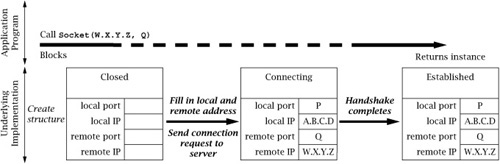
When the client calls the Socket constructor with the server’s Internet address, W.X.Y.Z, and port, Q, the underlying implementation creates a socket instance; it is initially in the Closed state. If the client did not specify the local address/port in the constructor call, a local port number (P), not already in use by another TCP socket, is chosen by the implementation. The local Internet address is also assigned; if not explicitly specified, the address of the network interface through which packets will be sent to the server is used. The implementation copies the local and remote addresses and ports into the underlying socket structure, and initiates the TCP connection establishment handshake.
The TCP opening handshake is known as a 3-way handshake because it typically involves three messages: a connection request from client to server, an acknowledgment from server to client, and another acknowledgment from client back to server. The client TCP considers the connection to be established as soon as it receives the acknowledgment from the server. In the normal case, this happens quickly. However, the Internet is a best-effort network, and either the client’s initial message or the server’s response can get lost. For this reason, the TCP implementation retransmits handshake messages multiple times, at increasing intervals. If the client TCP does not receive a response from the server after some time, it times out and gives up. In this case the constructor throws an IOException. The connection timeout is generally long, and thus it can take on the order of minutes for a Socket constructor to fail.
After the initial handshake message is sent and before the reply from the server is received (i.e., the middle part of Figure 6.6), the output from netstat on the client host would look something like:
   Active Internet connections
   Proto Recv-Q Send-Q Local Address   Foreign Address   State
   tcp        0      0 A.B.C.D:P       W.X.Y.Z:Q         SYN_SENT
where “SYN_SENT” is the technical name of the client’s state between the first and second messages of the handshake.
If the server is not accepting connections—say, if there is no program associated with the given port at the destination—the server-side TCP will send a rejection message instead of an acknowledgment, and the constructor will throw an IOException almost immediately. Otherwise, after the client receives a positive reply from the server, the netstat output would look like:
   Active Internet connections
   Proto Recv-Q Send-Q Local Address   Foreign Address  State
   tcp        0      0 A.B.C.D:P       W.X.Y.Z:Q        ESTABLISHED
The sequence of events at the server side is rather different; we describe it in Figures 6.7, 6.8, and 6.9. The server first creates an instance of ServerSocket associated with its well-known port (here, Q). The socket implementation creates an underlying socket structure for the new ServerSocket instance, and fills in Q as the local port and the special wildcard address (“*” in the figures) for the local IP address. (The server may also specify a local IP address in the constructor, but typically it does not. In case the server host has more than one IP address, not specifying the local address allows the socket to receive connections addressed to any of the server host’s addresses.) The state of the socket is set to “LISTENING”, indicating that it is ready to accept incoming connection requests addressed to its port. This sequence is depicted in Figure 6.7. The output from netstat on the server would include a line like:
   Active Internet connections
   Proto Recv-Q Send-Q Local Address   Foreign Address  State
   tcp        0      0 0.0.0.0:Q       0.0.0.0:0        LISTENING

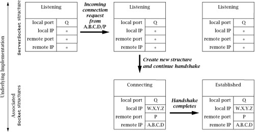

The server can now call the ServerSocket’s accept() method, which blocks until the TCP opening handshake has been completed with some client and a new connection has been established. We therefore focus (in Figure 6.8) on the events that occur in the TCP implementation when a client connection request arrives. Note that everything depicted in this figure happens “under the covers,” in the TCP implementation.
When the request for a connection arrives from the client, a new socket structure is created for the connection. The new socket’s addresses are filled in based on the arriving packet: the packet’s destination Internet address and port (W.X.Y.Z and Q, respectively) become the local Internet address and port; the packet’s source address and port (A.B.C.D and P) become the remote Internet address and port. Note that the local port number of the new socket is always the same as that of the ServerSocket. The new socket’s state is set to indicate that it is “Connecting” (technically called SYN_RCVD at the server side), and it is added to a list of not-quite-connected sockets associated with the socket structure of the ServerSocket. Note that the ServerSocket itself does not change state, nor does any of its address information change. At this point the output of netstat should show both the original, listening socket and the newly created one:
   Active Internet connections
   Proto Recv-Q Send-Q Local Address    Foreign Address    State
   tcp        0      0 0.0.0.0:Q        0.0.0.0:0          LISTENING
   tcp        0      0 W.X.Y.Z:Q        A.B.C.D:P          SYN_RCVD
In addition to creating a new underlying socket structure, the server-side TCP implementation sends an acknowledging TCP handshake message back to the client. However, the server TCP does not consider the handshake complete until the third message of the 3-way handshake is received from the client. When that message eventually arrives, the new structure’s state is set to “ESTABLISHED”, and it is then (and only then) moved to a list of socket structures associated with the ServerSocket structure, which represent established connections ready to be accept()ed via the ServerSocket. (If the third handshake message fails to arrive, eventually the “Connecting” structure is deleted.) Output from netstat would include:
   Active Internet connections
   Proto Recv-Q Send-Q Local Address    Foreign Address    State
   tcp        0      0 0.0.0.0:Q        0.0.0.0:0          LISTENING
   tcp        0      0 W.X.Y.Z:Q        A.B.C.D:P          ESTABLISHED
Now we can consider (in Figure 6.9) what happens when the server program calls the ServerSocket’s accept() method. The call unblocks as soon as there is something in its associated list of socket structures for new connections. (Note that this list may already be non-empty when accept() is called.) At that time, one of the new connection structures is removed from the list, and an instance of Socket is created for it and returned as the result of the accept().
It is important to note that each structure in the ServerSocket’s associated list represents a fully established TCP connection with a client at the other end. Indeed, the client can send data as soon as it receives the second message of the opening handshake—which may be long before the server calls accept() to get a Socket instance for it.
TCP has a graceful close mechanism that allows applications to terminate a connection without having to worry about loss of data that might still be in transit. The mechanism is also designed to allow data transfers in each direction to be terminated independently, as in the compression example of Section 4.5. It works like this: the application indicates that it is finished sending data on a connected socket by calling close() or by calling shutdownOutput(). At that point, the underlying TCP implementation first transmits any data remaining in SendQ (subject to available space in RecvQ at the other end), and then sends a closing TCP handshake message to the other end. This closing handshake message can be thought of as an end-of-stream marker: it tells the receiving TCP that no more bytes will be placed in RecvQ. (Note that the closing handshake message itself is not passed to the receiving application, but that its position in the byte stream is indicated by read() returning − 1.) The closing TCP waits for an acknowledgment of its closing handshake message, which indicates that all data sent on the connection made it safely to RecvQ. Once that acknowledgment is received, the connection is “Half closed.” The connection is not completely closed until a symmetric handshake happens in the other direction—that is, until both ends have indicated that they have no more data to send.
The closing event sequence in TCP can happen in two ways: either one application calls close() (or shutdownOutput()) and completes its closing handshake before the other calls close(), or both call close() simultaneously, so that their closing handshake messages cross in the network. Figure 6.10 shows the sequence of events in the implementation when the application on one end invokes close() before the other end closes. The closing handshake message is sent, the state of the socket structure is set to indicate that it is “Closing,” (technically called “FIN_WAIT_1”) and the call returns. After this point, further reads and writes on the Socket are disallowed (they throw an exception). When the acknowledgment for the close handshake is received, the state changes to “Half closed” (technically, “FIN_WAIT_2”) where it remains until the other end’s close handshake message is received. At this point the output of netstat on the client would show the status of the connection as:
   Active Internet connections
   Proto Recv-Q Send-Q Local Address    Foreign Address    State
   tcp        0      0 A.B.C.D:P        W.X.Y.Z:Q          FIN_WAIT_2

(FIN_WAIT_2 is the technical name for the “Half-closed” state at the host that initiates close first. The state denoted by “Closing” in the figure is technically called FIN_WAIT_1, but it is transient and is difficult to catch with netstat.)
Note that if the remote endpoint goes away while the connection is in this state, the local underlying structure will stay around indefinitely. When the other end’s close handshake message arrives, an acknowledgment is sent and the state is changed to “Time-Wait.” Although the corresponding Socket instance in the application program may have long since vanished, the associated underlying structure continues to exist in the implementation for a minute or more; the reasons for this are discussed on page 163.
The output of netstat at the right end of Figure 6.10 includes:
   Active Internet connections
   Proto Recv-Q Send-Q Local Address    Foreign Address    State
   tcp        0      0 A.B.C.D:P        W.X.Y.Z:Q          TIME_WAIT
Figure 6.11 shows the simpler sequence of events at the endpoint that does not close first. When the closing handshake message arrives, an acknowledgment is sent immediately, and the connection state becomes “Close-Wait.” The output of netstat on this host shows:
   Active Internet connections
   Proto Recv-Q Send-Q Local Address    Foreign Address    State
   tcp        0      0 W.X.Y.Z:Q        A.B.C.D:P          CLOSE_WAIT

At this point, we are just waiting for the application to invoke the Socket’s close() method. When it does, the final close handshake is initiated and the underlying socket structure is deallocated, although references to its original Socket instance may persist in the Java program.
In view of the fact that both close() and shutdownOutput() return without waiting for the closing handshake to complete, you may wonder how the sender can be assured that sent data has actually made it to the receiving program (i.e., to Delivered). In fact, it is possible for an application to call close() or shutdownOutput() and have it complete successfully (i.e., not throw an Exception) while there is still data in SendQ. If either end of the connection then crashes before the data makes it to RecvQ, data may be lost without the sending application knowing about it.
The best solution is to design the application protocol so that the side that calls close() first does so only after receiving application-level assurance that its data was received. For example, when our TCPEchoClient program receives the echoed copy of the data it sent, it knows there is nothing more in transit in either direction, so it is safe to close the connection.
Java does provide a way to modify the behavior of the Socket’s close() method, namely, the setSoLinger() method. setSoLinger() controls whether close() waits for the closing handshake to complete before returning. It takes two parameters, a boolean that indicates whether to wait, and an integer specifying the number of seconds to wait before giving up. That is, when a timeout is specified via setSoLinger(), close() blocks until the closing handshake is completed, or until the specified amount of time passes. At the time of this writing, however, close() provides no indication that the closing handshake failed to complete, even if the time limit set by setSoLinger() expires before the closing sequence completes. In other words, setSoLinger() does not provide any additional assurance to the application in current implementations.
The final subtlety of closing a TCP connection revolves around the need for the Time-Wait state. The TCP specification requires that when a connection terminates, at least one of the sockets persists in the Time-Wait state for a period of time after both closing handshakes complete. This requirement is motivated by the possibility of messages being delayed in the network. If both ends’ underlying structures go away as soon as both closing handshakes complete, and a new connection is immediately established between the same pair of socket addresses, a message from the previous connection, which happened to be delayed in the network, could arrive just after the new connection is established. Because it would contain the same source and destination addresses, the old message could be mistaken for a message belonging to the new connection, and its data might (incorrectly) be delivered to the application.
Unlikely though this scenario may be, TCP employs multiple mechanisms to prevent it, including the Time-Wait state. The Time-Wait state ensures that every TCP connection ends with a quiet time, during which no data is sent. The quiet time is supposed to be equal to twice the maximum amount of time a packet can remain in the network. Thus, by the time a connection goes away completely (i.e., the socket structure leaves the Time-Wait state and is deallocated) and clears the way for a new connection between the same pair of addresses, no messages from the old instance can still be in the network. In practice, the length of the quiet time is implementation dependent, because there is no real mechanism that limits how long a packet can be delayed by the network. Values in use range from 4 minutes down to 30 seconds or even shorter.
The most important consequence of Time-Wait is that as long as the underlying socket structure exists, no other socket is permitted to be associated with the same local port. In particular, any attempt to create a Socket instance using that port will throw an IOException.
The fact that different sockets on the same machine can have the same local address and port number is implicit in the discussions above. For example, on a machine with only one IP address, every new Socket instance accept()ed via a ServerSocket will have the same local port number as the ServerSocket. Clearly the process of deciding to which socket an incoming packet should be delivered—that is, the demultiplexing process—involves looking at more than just the packet’s destination address and port. Otherwise there could be ambiguity about which socket an incoming packet is intended for. The process of matching an incoming packet to a socket is actually the same for both TCP and UDP, and can be summarized by the following points:
The local port in the socket structure must match the destination port number in the incoming packet.
Any address fields in the socket structure that contain the wildcard value (*) are considered to match any value in the corresponding field in the packet.
If there is more than one socket structure that matches an incoming packet for all four address fields, the one that matches using the fewest wildcards gets the packet.
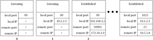
For example, consider a host with two IP addresses, 10.1.2.3 and 192.168.3.2, and with a subset of its active TCP socket structures shown in Figure 6.12. The structure labeled 0 is associated with a ServerSocket and has port 99 with a wildcard local address. Socket structure 1 is also for a ServerSocket on the same port, but with the local IP address 10.1.2.3 specified (so it will only accept connection requests to that address). Structure 2 is for a connection that was accepted via the ServerSocket for structure 0, and thus has the same local port number, but also has its local and remote Internet addresses filled in. Other sockets belong to other active connections. Now consider a packet with source IP address 172.16.1.10, source port 56789, destination IP address 10.1.2.3, and destination port 99. It will be delivered to the socket associated with structure 1, because that one matches with the fewest wildcards.
When a program attempts to create a socket with a particular local port number, the existing sockets are checked to make sure that no socket is already using that local port. A Socket constructor will throw an exception if any socket matches the local port and local IP address (if any) specified in the constructor. This can cause problems in the following scenario:
If the new incarnation of the client attempts to use the same local port number, the Socket constructor will throw an IOException, because of the other structure in the Time-Wait state. As of this writing, the only way around this is to wait until the underlying structure leaves the Time-Wait state.
So what determines the local/foreign address/port? For a ServerSocket, all constructors require the local port. The local address may be specified to the constructor; otherwise, the local address is the wildcard (*) address. The foreign address and port for a ServerSocket are always wildcards. For a Socket, all constructors require specification of the foreign address and port. The local address and/or port may be specified to the constructor. Otherwise, the local address is the address of the network interface through which the connection to the server is established, and the local port is a randomly selected, unused port number greater than 1023. For a Socket instance returned by accept(), the local address is the destination address from the initial handshake message from the client, the local port is the local port of the ServerSocket, and the foreign address/port is the local address/port of the client. For a DatagramSocket, the local address and/or port may be specified to the constructor. Otherwise the local address is the wildcard address, and the local port is a randomly selected, unused port number greater than 1023. The foreign address and port are initially both wildcards, and remain that way unless the connect() method is invoked to specify particular values.
1. | The TCP protocol is designed so that simultaneous connection attempts will succeed. That is, if an application using port P and Internet address W.X.Y.Z attempts to connect to address A.B.C.D, port Q, at the same time as an application using the same address and port tries to connect to W.X.Y.Z, port P, they will end up connected to each other. Can this be made to happen when the programs use the sockets API? |
2. | The first example of “buffer deadlock” in this chapter involves the programs on both ends of a connection trying to send large messages. However, this is not necessary for deadlock. How could the |
[1] The same thing generally applies to reading data from the Socket’s InputStream, although calling read() with a larger buffer does not guarantee that more data will be returned.