Chapter 5. Lights, Camera, Action!
As you move forward with your learning about graphics in this book, you need to understand how your “scene” (the things rendered in your game) is visualized. Much like a director working on a movie, you are responsible for dictating how your world is visualized. You use a camera to do this, just as a director would. You also explore easier ways to store the objects that make up your worlds. In this chapter, you learn about:
• Controlling the camera in your 3D scenes
• Rendering models
Well, actually, lights and action are described later, but one out of three isn’t a bad start. When people speak about cameras in three-dimensional (3D) games, they rarely speak about a rendered camera, but more the spot in which your viewpoint comes from. Even the name of the matrix describing this is the view matrix. Now is the time to take a look at the thing called the camera.
Why Do I See What I See?
Much like you’d expect, a camera in a 3D graphics scene is basically the same thing as a camera in real life. It has a position where the camera is in the world, and it takes a picture of the world to show you on a flat surface. In 3D graphics, it is the same thing; the camera dictates how you see the world.
Of the three most common matrices you set when rendering, two of them are used to control the camera. The world matrix is used to define the world and is unrelated to the camera, but the view matrix and the projection matrix are each used to modify how the camera is either positioned or the properties it uses to render. Let’s look at a quick example.
First, you need to create a new Windows Game project and add the box.fbx model to your content project. Models are discussed later in this chapter, but for now, load it and render it to show camera interaction. You need to add a new variable to render this model, so add the following:
Model model;
Then, update your LoadContent method to instantiate this object:
![]()
Ignore the second line for now, as it is discussed more in Chapter 6, “Built-In Shader Effects.” It is being added right now so the scene doesn’t look flat and ugly. Naturally, the first line loads the model (which you probably guessed was a box). Finally, you need to render the box using a camera, so add the following to your Draw method after the call to Clear:

Running this application shows you a box rendering in the center of your window, such as on the one you see in Figure 5.1.
Figure 5.1. A simple scene’s camera rendering

The camera in that scene is defined by the CreateLookAt method and the CreatePerspectiveFieldOfView method. They define how the final image of your scene looks and the position, properties, and lens type of the camera. The CreateLookAt method returns the view matrix, whereas the other returns the projection matrix. Let’s look at those in more depth.
View Matrix
The view matrix is the easiest to visually conceptualize, as it has only three components: the position of the camera in world space, where the camera looks, and what direction is up. In the example you used a moment ago, the camera is located at a point (2,3,–5) in world space, looking at the origin (0,0,0), with the up direction being the constant up direction on the Vector class (0,1,0); you can visualize this as seen in Figure 5.2.
Figure 5.2. How the camera views the scene

Notice how you see a portion of the cube? What if you moved the camera somewhere else to see a different portion of the cube? Try replacing that first vector with a new Vector3(3,–2,4) and see how your view changes. Notce that you’re looking at a completely different angle of the cube, as seen in Figure 5.3.
Figure 5.3. How the camera views the scene from another angle

The second parameter to CreateLookAt is also easy to conceptualize because it is the position the camera looks toward. In the example given, the box is located at (0,0,0), and the camera looks there, too, so the box is in the center of the screen. If you changed the second parameter instead to a vector of (–2,0,0), you would expect that the camera would be looking more to the left (negative x is to the left when the camera is in the positive Z axis), so the box should be more to the right. By extension, using a vector of (2,0,0) would make the box appear to the left (because the camera looks to the right of it).
Of course, if you changed the location of the camera to the opposite side of the Z axis (3,–2,4), then the look at point of (2,0,0) would cause the box to appear on the right because the camera looks to the left of it (positive x is to the left when the camera is in the negative Z axis).
The final parameter to the CreateLookAt method is the vector that describes what up is. In the previous example, you used Vector3.Up, which is a vector of (0,1,0), which means the up direction of the camera follows the positive Y axis. Imagine the camera is your eyes (because after all, that is what it is), and you’re standing on a flat surface. The positive Y axis (0,1,0), is up to you. If you stood on your head, up to you would be the negative Y axis, and everything would appear upside down. Change your last parameter in the CreateLookAt method to Vector3.Down, and notice that you’re still looking at the box in the same way; it’s just upside down now, much like it would be if you looked at it while standing on your head.
By the same mechanism, if you tilted your head to the right, so up was Vector3.Right, you’d still see the same image, but instead of being right-side up or upside down, it would be rotated 90 degrees. You can visualize the up vector as the imaginary ray that runs from the center of the camera through the top of the camera, as you can see in Figure 5.4.
Figure 5.4. Which way is up?
Projection Matrix
Compared to the view matrix, the projection matrix is much more difficult to explain! When thinking of the view matrix as the camera, you can think of the projection matrix as the lens. There are many more lens types than cameras!
The method we used in the example earlier to describe our projection matrix was CreatePerspectiveFieldOfView, which creates a perspective projection matrix, based on the field of view. As was discussed in Chapter 4, “Introduction to 3D Graphics,” perspective is what makes things closer appear larger, whereas things further away appear smaller. There are two major types of projection matrices you can create—perspective and orthographic—both of which are discussed next.
Perspective
The perspective matrix lets you define the viewing frustum. To visualize what this is, imagine a pyramid. The tip of the pyramid is the location of the camera (or your eye). Anything that exists inside that pyramid can be seen; anything that exists outside of the pyramid cannot be seen. The various methods to create perspective projection matrices are used to define the size and shape of this pyramid. See Figure 5.5.
Figure 5.5. The viewing frustum

First, let’s look at the matrix used in the example. It was created using the CreatePerspectiveFieldOfView method, which has a few parameters. The first is the field of view parameter, the second is the aspect ratio, and the last two are the near and far planes, but what do these actually mean? The field of view is the angle that the top of the pyramid forms and is specified in radians. In the example, we used an angle of 45 degrees, which is somewhat common. If you used 90 degrees (MathHelper.PiOver2) instead, you’d have a much larger field of view, and thus, a larger viewing area. This would cause your rendered objects to appear smaller because the same screen area would have to render a larger world area (see Figure 5.6 for more information on the math of the field of view or fov).
Figure 5.6. The math behind field of view

The second parameter is the aspect ratio, which is simply the width of your scene divided by the height of your scene. Notice here that you use the Viewport property of the GraphicsDevice and you use the AspectRatio property from that. This is the most common aspect ratio you use, but if you render to something other than the back buffer (say a render target), you might want to render at a different aspect ratio. The aspect ratio here is just like the aspect ratio you see on televisions. Standard-definition televisions have a 1.33 (4/3) aspect ratio, whereas most high-definition televisions have a 1.77 (16/9) aspect ratio. Most of the old resolutions you’ve seen in computers were 1.33 (4/3) aspect ratios (640×480, 800×600, 1024×768, and so on).
Aspect Ratio, Integers, and Floats
Aspect ratio is defined as a float value. If you are calculating your aspect ratio using the width divided by the height, and your width and height parameters are both integers, so be sure to cast at least one of them to float before the division. If you do not, the compiler does the division as integers and casts the final value to float, which isn’t what you want. For example, if you try to calculate the aspect ratio of a standard definition television set, you use the width of 4 divided by the height of 3, and in integer math, 4/3 = 1. It would then cast the 1 to the float of 1.0f, which is incorrect. If you cast one of the values to float before the division, though, you get 4.0f/3 = 1.3333f, which is the value you want.
The last two parameters are the near and the far planes of the frustum. Anything closer than the near plane or anything farther than the far plane is not visible. You can think of the far plane as the base of the pyramid, whereas the near plane is where you would “cut off” the top of the pyramid.
See Figure 5.6 for more information on the math for a field of view projection matrix.
Using the field of view is one way to create a perspective projection matrix, but not the only way. There are two other helper methods you can use, namely CreatePerspective and CreatePerspectiveOffCenter. Each of these creates your pyramid in slightly different ways, but before we get to that, let’s modify the example to draw a lot of boxes so it’s easier to see how the changes behave. Replace your draw code with the following (this might seem way more complicated than it is) to see a series of boxes like you see in Figure 5.7:

Figure 5.7. The view of a bunch of boxes

Although this seems more complicated than it is, all you’re doing here is drawing nine different boxes. They’re rendered in a square pattern with each one rendered at a different spot in the world and at a variety of different depths. You should notice how ones that are farther away are slightly smaller. The radius calculation is discussed in more detail later this chapter when we talk about the models. The rest is just simple math to position the boxes around the screen.
The CreatePerspective method takes only four parameters to describe what your pyramid should look like. The first one is the width of the top of the pyramid (where the near plane cuts it off), and the second is the height of the same. The third parameter is the distance to the near plane, and the fourth is the distance to the far plane (or the base of the pyramid). Modify your matrix creation as follows:
Matrix proj = Matrix.CreatePerspective(1.0f, 0.5f, 1.0f, 100.0f);
If you run the program now, notice that the picture has changed somewhat dramatically. All nine boxes don’t even appear fully onscreen anymore! This is because you changed the shape of your viewing frustum (or the pyramid), and portions of those boxes are now outside of it. See Figure 5.8.
Figure 5.8. Modifying the view frustum directly

The CreatePerspective method assumes that you are looking at the center point of the near plane (formed by the width and height), but that isn’t a requirement either. You can use the CreatePerspectiveOffCenter method, which is similar to the nonoff center method. Rather than a width and height being passed in, you instead must pass in the left, right, top, and bottom positions. For example, if you use the following instead of the CreatePerspective method you used earlier, you would get the same output:
proj = Matrix.CreatePerspectiveOffCenter(-0.5f, 0.5f, -0.25f, 0.25f, 1.0f, 100.0f);
This is because you have the same width and height, and they are centered. Using this method enables you even more control over the location and size of the viewing frustum.
There is also another common type of projection matrix, the orthographic projection.
Orthographic
Much like a perspective matrix, an orthographic matrix builds a viewing frustum, but instead of a pyramid shaped structure, it is more rectangular. The viewing frustum does not get larger between the near plane and the far plane, and no perspective foreshortening occurs. All objects of the same size are rendered the same size, regardless of how far they are from the camera.
There are two helper methods to create these types of projection matrix: CreateOrthographic and CreateOrthographicOffCenter. Much like the perspective counterparts, these describe the orthographic volume, with the former being centered and the latter capable of being off center. If you replaced your project matrix with the following, you would see all nine boxes, but they’d all appear on the same plane:
proj = Matrix.CreateOrthographic(15.0f, 15.5f, 1.0f, 100.0f);
With the basics of projection matrices and view matrices out of the way, now you can actually create some camera types!
Camera Types
Although any individual game probably has only a single type of camera, there are a wide variety that can be used—cameras that follow the players, cameras that never move, and cameras that change depending on the circumstances...the possibilities are endless.
Static Cameras
The easiest camera to think about is a static camera. As the name implies, a static camera doesn’t move. It sits there and just looks out. The camera’s you’ve been using in this chapter so far are simple static cameras. Let’s create a helper class that is your camera type. Right-click your project, select Add->New Item, choose Game Component (calling it CameraComponent.cs) and add the following variables to it:
protected Matrix view;
protected Matrix proj;
You need a way to get these values back from your component, so add two property getters for them now:
public Matrix View
{
get
{
return view;
}
}
public Matrix Projection
{
get
{
return proj;
}
}
You also need to initialize these to something reasonable, so in your Initialize overload, add the following:
view = Matrix.CreateLookAt(new Vector3(0, 0,-16),
Vector3.Zero, Vector3.Up);
proj = Matrix.CreatePerspectiveFieldOfView(MathHelper.PiOver4,
Game.GraphicsDevice.Viewport.AspectRatio, 1.0f, 100.0f);
With that, you’ve made yourself a fixed static camera. Let’s modify the game to use this camera instead. Add a new variable to your Game class to hold the camera:
CameraComponent camera;
Then, in your game’s Initialize overload, add this component to your game’s component list:
Components.Add(camera = new CameraComponent(this));
Then finally, switch your call to Draw on the model to use this camera component:
model.Draw(Matrix.CreateTranslation(pos), camera.View, camera.Projection);
If you run the application now, you see a slightly different view because your camera is in a different location. This camera can be extended to support different types of cameras, which you should experiment with.
Models
Earlier in this chapter, you were likened to a director, using your camera to bring your world to life. Just like the directors in movies who often use models to be the stars in their films, you will do the same thing!
What Is a Model?
A model is essentially a collection of geometry that is rendered together to form an object in the world. You’ve used them throughout this chapter already, but let’s take more time now to go through the Model class itself, which has quite a bit of data. You remember from last chapter when you were rendering things with vertex buffers and index buffers? Models use these objects, too, and are a great way to hold geometry.
If you use a Digital Content Creation (DCC) package, such as SoftImage Mod Tool (see Figure 5.9), to create your objects, when you export those creations to a file (such as an .fbx file or an .x file), you can add these to your content projects to use the Model content importer. These are loaded into the Model class.
Figure 5.9. A DCC package creating a model

Models
The first method you can look at on the Model class is the Draw method, because you’ve already used it in this chapter. This method (as the name implies) draws the model using the supplied transform with the provided view and projection matrices and with the defaults for everything else. It is a quick and easy way to show something onscreen as you’ve seen so far.
A Tag property can also be used to store any type of data. Many content importers also include extra information in this object for the game to use. Let’s take a look at the Meshes property next.
Meshes
The Meshes property returns a collection of ModelMesh objects. In the box you’ve been using up until now in this chapter, each model has only had one mesh inside of it. Although that is the simplest form of a model, models can be extremely complex. Imagine a model that represents a city. The city would have roads, buildings, and signs. Each of these objects can be represented by a different model mesh, whereas the combined set of meshes is the full model.
Each mesh also has a Draw method that can be used to render the mesh separately, but notice that this method has no parameters. This does the rendering of the mesh, but it does so with the current settings of the effects rather than setting the world, view, and projection matrices that the model’s Draw method does. This is because there is extra information inherent to each mesh that might change where it is in the world; we discuss this later in this chapter.
Another piece of information found on the mesh is the BoundingSphere property, which describes a sphere that encompasses the entire mesh. The bounding sphere object has a few fields and methods that are used for a variety of reasons. The Center and Radius fields are used to describe the sphere, whereas there are a few helper methods such as Contains and Intersects used to detect objects in the sphere. You can also Transform the sphere using that helper method.
Each mesh can also have a Name (that can be set by your code or set during content importing and loading) and Tag similarly to the model itself. Aside from the bones (which are discussed in a moment), the last two properties on the mesh are Effects and MeshParts, which are interrelated. The Effects collection is the collection of effects that is associated with each mesh part and controls how the mesh parts are rendered. The number of effects and mesh parts is identical, and you can update or modify the effects for any of the mesh parts you’d like.
Note
Effects are discussed in depth in Chapters 6 and 8, “Built-In Shader Effects,” and “Introduction to Custom Effects.”
Each mesh part is the portion of the model that is actually rendered. Notice that one of the properties it has is the Effect that this part uses. Changing this property also affects the Effects property on the mesh at the same index this mesh part exists at. The rest of the properties contain the information about the geometry and gives you the information you need to draw the mesh part with the DrawIndexedPrimitives method. You can see the IndexBuffer and VertexBuffer properties that hold the index and vertex data and the PrimitiveCount to dictate how many triangles to draw. When drawing data using this information, you can always use a primitive type PrimitiveType.TriangleList.
A few other pieces of information on the mesh part can be used when setting the vertex buffer and index buffer to the device, such as NumVertices (which is the number of vertices in the buffer), VertexOffset (which is the number of vertices to skip before getting to the vertices required for this mesh part), and StartIndex (which is the number of indices to skip before getting to the first index required by this mesh part). Like the Model and ModelMesh before it, this also includes a Tag property.
Normally each mesh part is separated from the other portions of the mesh based on the material it uses to render itself. You see the term material used often in DCC packages and throughout literature on this subject. For the purposes of this book, you can consider the material to be the combination of the Effect used to render the geometry and the textures required to do so.
For example, in the imaginary city model, you can also imagine that the road portions of the model are all one mesh. If you had three different kinds of roads, such as a paved street, a gravel road, and a dirt road, you would potentially use different textures and possibly even different effects for those, so your roads mesh would have three different mesh parts: one for the paved street, one for the gravel roads, and a final one for the dirt roads.
See Figure 5.10 for an example of how models, meshes, and mesh parts are all interrelated.
Figure 5.10. Models, meshes, and mesh parts

Throughout the discussions of models, you didn’t about one particular type of object, so let’s take a look at it now.
Bones
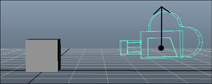
The ModelMesh has a property ParentBone that you skipped, and the model itself had quite a few methods and properties that deal with bones. What exactly are bones (aside from things like a femur or a song by Alice in Chains)? At a high level, bones are what connect each mesh to every other mesh. See Figure 5.11 for an example of a simple model with three meshes.
Figure 5.11. A model with three meshes

Let’s assume you want to build a model of a person, and what is in Figure 5.11 is what you have so far. You have the sphere representing the head, a cylinder representing the neck, and a cube representing the torso. Each of these body parts can be considered a mesh in the larger full model, and bones are what tie these together. Each bone tells you the relationship between itself, its parent, and its children.
One of the meshes in the model is the root bone. This is the mesh that is the root of the other meshes and is accessed via the Root property on the model, which returns a ModelBone object. These objects have a few different properties to help explain the relationship of that particular bone to the others in the model. First, it has the Children property that is a collection of ModelBone objects that define the children of this bone. You can also get the Parent (again, as a ModelBone) of this bone. Like the mesh, you can also get the Name of this bone, which can be set during content import and creation.
You also see the Index property, which is the index of this bone in the model’s Bones collection (which is the entire collection of bones for the model). Finally, you see the Transform property, which is the transform of this bone in relation to its parent. Let’s look at an example.
In the model in Figure 5.11, you can imagine that the torso would be the root bone with a single child being the cylinder forming the neck, which in turn, has a single child as the sphere forming the head. If the model had arms and the torso was the root, you could extrapolate out that it would have multiple children for the neck, arms, and legs.
Now, assume that the torso has a transformation of Matrix.Identity. It has no scale or rotation and it is located at the origin (0,0,0). However, the neck is approximately three units above that, so the Transform property of the neck bone is Matrix.CreateTranslation(0,3,0). You can see that the head is even higher, yet approximately three units above its parent, the neck, so its Transform property would be Matrix.CreateTranslation(0,3,0), even though it is approximately six units above the torso! If your head was slightly turned, you could instead have its Transform property be Matrix.CreateRotationX(MathHelper.PiOver4) * Matrix.CreateTranslation(0,3,0). The transform is always based on the parent bone and not the model itself. This is especially useful for animated characters because like in this example, you can easily have your head turn side to side by simply changing the rotation transform on a single bone, rather than repositioning the entire set of geometry.
There are also three methods on the Model class you can use to get or set these transforms. You can use the CopyBoneTransformsTo method to create a copy of the transforms each bone has into a new array of matrices (for example, what you might want to pass into an effect). You can also use the similar (but opposite order) method of CopyBoneTransformsFrom to update all the bones with these new transforms. There is also another helper method called CopyAbsoluteBoneTransformsTo, which like the nonabsolute one, copies all the transforms into an array of matrices. The difference is this one combines each child’s transform with all of its parent transforms.
What this means, in the previous example, by using CopyBoneTransformsTo you would have an array of three matrices: the first member having Matrix.Identity and the second two members having Matrix.CreateTranslation(0,3,0). However, if you use CopyAbsoluteBoneTransformsTo, you would have the same array of three matrices with the first two members remaining the same, but the third member would instead be Matrix.CreateTranslation(0,6,0) because it combines the transform with its parents transforms.
Rendering Models
Enough of all this text—’let’s actually use the model class to draw some stuff onscreen! Create a new Windows Game project and add any model you’d like from the downloadable examples. Now, get ready to do some rendering. You need to add a variable for your model, such as:
Model model;
Next, update your LoadContent method to get the object instantiated:
model = Content.Load<Model>("YourModel");
foreach (ModelMesh mm in model.Meshes)
{
foreach (Effect e in mm.Effects)
{
IEffectLights iel = e as IEffectLights;
if (iel != null)
{
iel.EnableDefaultLighting();
}
}
}
Naturally, you need to replace the YourModel with whatever model you picked. Although you haven’t gotten to the effects yet, the next section of code enables default lights for all portions of the model that have it. This is discussed in more detail in Chapter 6, but for this discussion, it makes your models look nice.
Note
By default, models loaded through the content pipeline have default effects set, depending on the materials set in the DCC package used to create it. A common effect used is BasicEffect, which is discussed in Chapter 6.
Next, because you’ve picked any random model you wanted, and models can be of a wide variety of sizes, you need to add a helper method to get the size of the largest mesh in the model, so you can scale it correctly. In a real game, you never have to do this trickery because you control the scale and size of the models, but here, it’s a quick operation to have a good guess. Add this private function to your game class:
private float GetMaxMeshRadius(Model m)
{
float radius = 0.0f;
foreach (ModelMesh mm in m.Meshes)
{
if (mm.BoundingSphere.Radius > radius)
{
radius = mm.BoundingSphere.Radius;
}
}
return radius;
}
This goes through each mesh and finds the one with the largest bounding radius and returns the largest radius it finds. Now you can add another helper method to draw the model, which you’ update a few times over the next few pages to see the various ways of rendering the model. The first one is the easiest:
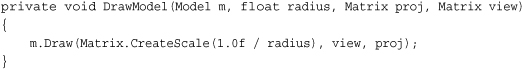
The only thing interesting you use for the model is the world matrix. You create a scale that makes the model approximately 1.0f units. This enables you to use a static camera regardless of model size and still see it in its entirety.
Finally, you need to do the actual rendering. Replace your Draw method with the following:

Notice here that you’re positioning the camera slightly offset from the model and four units away. This is possible only because of the scaling done in the DrawModel call; otherwise, you have to base your camera size on the size of the model. Nothing here is exactly new, though, and running the application shows your model rendered on screen.
Next, let’s add the new method DrawModelViaMeshes to use the meshes instead of the single Draw method on model. Add the following method and update your DrawModel call to use this one instead:

This also needs a helper method to get the parent bone transform, so add this, too:
private Matrix GetParentTransform(Model m, ModelBone mb)
{
return (mb == m.Root) ? mb.Transform :
mb.Transform * GetParentTransform(m, mb.Parent);
}
So, what is going on here? You set the initial world matrix you want to use as the basis for everything, much like you did in the previous one-line call, but after that, things seem to get much more complicated! In reality, this is straightforward. For every mesh in your model, you go through the effects and set the matrices each needs. The view and projection matrices are the same for every effect (because you don’t want the camera moving around based on which portion of the model you’ render); however, the world matrix is vastly different.
Each mesh sets its world matrix to the parent’s world matrix combined with the constant world matrix for the model. Notice that the helper method to get the parent’s world matrix is recursive. Because each bone’s transform is relative to its parent’s transform, to get the full transform for any bone in the model, you need to combine its transform with all of its parents, which is what the helper method does. It stops when it gets to the root bone because it has no parent and simply returns the root bone’s transform.
Note
In a real game, you do not want to use this recursive function every single frame as you did here to get the bone transforms. You would instead cache them (and use perhaps the CopyAbsoluteBoneTransformsTo helper method), but it was done this way to illustrate the concept.
If you want even more control, however, you can render everything in the model exclusively through the device methods without ever calling one of the helper Draw methods. Add yet another helper method to draw the model via the vertex data itself and update your DrawModel call to use this one instead:

Notice the similarities between this one and the last one. You still need to enumerate through each of the meshes; however, instead of calling the Draw method on the meshes, enumerate through each of the mesh parts. You set the world, view, and projection matrices as you did before, although the actual rendering is done much differently. Much like you did in Chapter 4, the rendering happens directly through the GraphicsDevice. You learn in subsequent chapters that effects can have multiple passes (where you render the same thing multiple times with different effects), and this code handles the situation by enumerating through the effects before drawing.
You can see that the data needed to do the rendering is on the ModelMeshPart class. You need to set the vertex and index buffers to the device, which are on the part, and then the data needed to make the DrawIndexedPrimitives call are also there. By default, models loaded via the built-in importers from the content pipeline require the primitive type to be TriangleList, although creating your own importers can change this if you want to change it.
Summary
In this chapter, you learned about the camera and the view and projection matrices. You were introduced to the model class and learned how to render objects in the world with it.
In the next chapter, you look at the effects runtime and the built-in effects that are part of the framework.