Chapter 8. Introduction to Custom Effects
If you want the ultimate control over the graphics in your game you will want to write your own custom shader effects. Writing your own effects allows you the developer to control how the graphics hardware renders the geometry in your game.
In this chapter you will learn:
• The different parts that make up a custom effect file
• How to create your first custom effect file
• Vertex coloring and texturing
• Numerious lighting models for directional and point lights
• Setting effect states using an effect
Although XNA Game Studio 4.0 provides five built-in effects to use in your game, you are not limited to just these five for your Windows and Xbox 360 games. Underneath the five built-in effects are compiled effects graphics programs that implement the features that are exposed by the different types.
What Is a Custom Effect?
Custom effects enable you to write an effect file that contains the vertex and pixel shaders that determine how the geometry you draw is transformed and shaded before being outputted to the screen. This gives you tremendous control over how geometry is rendered in your game. With this control also comes some additional difficulty in programming and debugging your graphics code.
Although custom effects work in both the Reach and HiDef profiles, custom effects are not supported on Windows Phone 7.
High Level Shading Language
Effect files in XNA Game Studio are written in the High Level Shading Language or HLSL for short. HLSL was created by Microsoft for use by applications written using Direct3D. The underlying XNA graphics stack is built on Direct3D and thus uses HLSL as the effect shading language.
The syntax of HLSL is similar to C but with additional language support specifically designed for graphics operations.
HLSL supports many of the common keywords found in C such as bool, int, if, and else but also have specific keywords such as sampler, technique, and pixelshader.
HLSL also supports built-in intrinsic functions that are used in many graphics algorithms. For example, the dot(a, b) intrinsic returns the dot product scalar value between two vectors a and b.
HLSL has multiple versions, which can differ from the number of compiled instructions that can be used, the number of textures that can be accessed, to the actual keywords and intrinsic functions that are available. These versions are called shader models and can differ from the vertex to the pixel shaders. If your game is targeting the Reach profile, you can use the 2.0 shader model version. The HiDef profile supports shader model 3.0+.
Note
The Xbox 360 supports a special shader model version of 3.0, which includes instructions that are not available on other platforms such as vfetch. The list of available instructions can be found in the XNA Game Studio documentation.
This chapter is focused on getting you started on writing your first few effects and does not cover HLSL in depth. There are many books dedicated just to the topic of writing effects and is beyond what can be covered in just one chapter. You receive a good foundation to start experimenting with your own effects and will have the basic understanding so you can read about other types of effects.
Creating Your First Custom Effect
Let’s start with a new effect file. Effect files generally end with the .fx extension. Create a new XNA Game Studio Windows project. Then right-click the content project and select Add -> New Item (see Figure 8.1).
Figure 8.1. Add new content item menu

The Add New Item dialog displays a few of the different content types supported by XNA Game Studio. Select the Effect File listing and name it CustomEffect.fx. Finally, click the Add button (see Figure 8.2).
Figure 8.2. Add New Item dialog

The CustomEffect.fx file is not added to your content project. Effect files are built using the content pipeline using the Effect importer and processor. Because effect files contain code that is run on the graphics processor, the code needs to be compiled into a binary format suitable to run on the graphics hardware. This is similar to how a C application must be compiled to run on your Windows PC. The content pipeline compiles your effect file and reports build errors. Just like your game code, the effect file can contain syntax errors that are reported in the build output window in Visual Studio.
Parts of an Effect File
Double-click the newly created CustomEffect.fx file to view the contents of the file in the Visual Studio editor. Notice that the newly created file is not empty. The file is filled with the default effect file template to help you get started writing your effect.
Global Variables
The first part of the effect template declares three global variables that can be used from within the shaders you write.
float4x4 World;
float4x4 View;
float4x4 Projection;
// TODO: add effect parameters here.
The World, View, and Projection matrices are used to transform the geometry from local space into screen space as described in Chapter 4, “Introduction to 3D Graphics.” Notice that the variable type is not matrix, but is instead float4x4 (pronounced float four by four). This is essentially a four-by-four array of floats, which can be used to represent a 4×4 matrix. The TODO comment lets you know that this is the location where you can add new global parameters to the effect file.
Vertex Structures
The next section of the template defies two structures.

These structures are used to define what the input and output types are for the vertex shader. Refer to Chapter 4 where we discuss the graphics pipeline the vertex shader is used to transform the geometry from local space into screen space.
Input Vertex Structure
The first structure VertexShaderInput defines how the geometry will be passed into the shader. In this case, only the position of the geometry is passed into the shader with the name Position and has a type of float4. Notice that to the right of the variable is POSITION0. This is an input semantic that defines what each field represents in the vertex. It is used to define which portions of the input vertex stream correspond to the fields of the vertex structure in the shader.
When geometry is drawn in a game, a VertexDeclaration must be specified in order for the graphics hardware to determine how each field in a vertex element is used. The graphics hardware can then pass each of the vertices into the vertex shader.
The type used by the vertex in your game and the type used in the shader don’t have to match. The graphics card tries to map the vertex data the best it can given the hints from the semantics. For example, your VertexBuffer might contain the positions as Vector3 values, which contains three floats, but your input vertex structure might be expecting a float4. The first three components will be copied into the input vertex structure and the final w component will be left blank.
Output Vertex Structure
The output vertex structure is used to define what values are passed out of the vertex shader and into the pixel shader. Although the vertex shader is run for each geometry vertex that is drawn, the pixel shader is run for each pixel that makes up the triangle that is drawn.
The output vertex structure is often used as the input structure for the pixel shader, but this is not required. What is required is for the vertex shader to output a position. The position is required because it is used to determine how the triangle should be displayed on the screen. If portions or all of the triangle corners are not going to be displayed on the screen, then the pixel shader is not drawn for these pixels.
You might already notice something of importance. Although the vertex shader is run exactly once per vertex, the pixel shader can be run from 0 to the total number of pixels on the screen for each triangle. So there is no one-to-one relationship between the vertex and pixel shaders. How does the output from the vertex shader correspond to the input of the pixel shader when it can be run many more times than the vertex shader?
The answer is that the values from the vertex shader do not directly pass into the pixel shader. The values first pass through an interpolater. The interpolater does exactly what its name describes, which is to interpolate values across the face and edges of the triangle.
After the vertices of the triangle are passed through the vertex shader, the pixels that make up the triangle are determined and the pixel shader is run for each of the pixels. The interpolator is used to determine the values between each vertex. For example, if one vertex has and X position of 0.1 and another has an X position of 0.5, then the pixel that is halfway between the two on the edge of the triangle has an X value of 0.3.
Along with the position values, other values can be interpolated across the triangle such as color if the vertices or texture coordinates.
Vertex Shader
The next section of the effect template defines the vertex shader.
VertexShaderOutput VertexShaderFunction(VertexShaderInput input)
{
VertexShaderOutput output;
float4 worldPosition = mul(input.Position, World);
float4 viewPosition = mul(worldPosition, View);
output.Position = mul(viewPosition, Projection);
// TODO: add your vertex shader code here.
return output;
}
This is a very simple vertex shader. A new instance of the VertexShaderOutput structure is defined and used to return the final position at the end of the shader. The vertex shader then takes the input position and multiples it by the World matrix first to move the position into world space. It then multiplies the position by the View to move the position into view space. Finally, it multiplies the position by the Projection to move the it into projection or clip space.
Pixel Shader
The output position from the vertex shader determines all of the pixels that are displayed on the screen. The pixel shader is then run for each of the pixels.
The following simple pixel shader is defined by the new effect template.
float4 PixelShaderFunction(VertexShaderOutput input) : COLOR0
{
// TODO: add your pixel shader code here.
return float4(1, 0, 0, 1);
}
Notice that the input to the pixel shader function takes an argument of the type VertexShaderOutput. Also notice that the output of the pixel shader is a float4 that represents the color to write to the color buffer. The COLOR0 semantic is used to tell the graphics hardware the pixel shader plans to output the color using the float4 return value of the shader.
This simple shader outputs a solid color of red. A float4 color is storage in RGBA format. This means that the X component of the float4 is the red channel. The green, blue, and alpha values are stored in the Y, Z, and W components respectively.
Techniques and Passes
The last section of the effect template defines the techniques and the passes they contain.
technique Technique1
{
pass Pass1
{
// TODO: set renderstates here.
VertexShader = compile vs_2_0 VertexShaderFunction();
PixelShader = compile ps_2_0 PixelShaderFunction();
}
}
A technique is a collection of passes that are designed to run for each triangle. An effect file must contain at least one technique, but it can contain many techniques. Multiple techniques can be used when you need to alter which vertex and pixel shaders to use for particular geometry. For example, multiple techniques are used in the five built-in effects to handle the different types of input vertices that are drawn using the effects.
An effect pass defines which vertex and pixel shader should be used by the graphics hardware. The shader version along with the compile keyword determine how the vertex and pixel shaders should be compiled. The default template uses shader model 2 as the default, so vs_2_0 is used for the vertex shader and ps_2_0 is used for the pixel shader.
Each effect pass can also contain a set of render state to set before drawing geometry. Like the state objects discussed in Chapter 7, “States, Blending, and Textures,” these settings enable another method to set the graphics device settings to use while rendering geometry.
This brings you to the end of the new effect file template. It is not too complex, but this program runs many times very quickly on the graphics hardware. The complexity of your effects has a direct influence on the performance of drawing geometry using your effect. Some operations are more expensive than others, but a general tip is to keep the number of operations to a minimum.
Drawing with a Custom Effect
So you have your first custom effect file but nothing to show for it on the screen. Let’s get started by drawing a quad with the new effect file.
Define the following two member variables to hold the Effect and the array of vertices make up the two triangles in the quad.
Effect customEffect;
VertexPositionColor[] userPrimitives;
The Effect type is used with custom effects and is the base type of the five built-in effects. There are a number of built-in vertex types. The VertexPositionColor contains both the vertex position and the color for the vertex. All built-in vertex types implement the IVertexType interface that requires the vertex type to specify the VertexDeclaration. As we discussed before, the VertexDeclaration is used to tell the graphics hardware how the fields of the vertex should be used, such as position and color.
Next, in the games LoadContent method, load the Effect and define each of the vertices.
Notice that the Effect is loaded through the content pipeline. After loading the effect, set three properties for the World, View, and Project matrices. Although the built-in effects expose these as properties in the API surface, your Effect can’t because there is no guarantee that the Effect will use those global variables. Instead, use the Parameters collection and specify the parameter by string name.
Finally, in the games Draw method, tell the graphics card that you are using this specific effect and to draw the two triangles.
Before using an Effect, call Apply on the specific EffectPass you plan to use. In this case, you know there is only one EffectTechnique, so use the CurrentTechnique and there is only one EffectPass, so use index 0.
Now you are ready to draw. Press F5 and see the glory that is your first effect. Figure 8.3 shows an example of what you should see.
Figure 8.3. Drawing a quad with your first custom effect

Well that’s not too exciting, but it draws a pure red quad to the screen. Notice that the colors that were defined for each vertex are not used because the template pixel shader just outputs the single red color and does not use the vertex color. Don’t worry about it—it gets better looking from here.
Vertex Color
Now it’s time to add a little color to the quad. The last example outputted a single red color for each pixel. Let’s take the color for each vertex and pass it through the pixel shader so it can output the color.
The vertices that make up the quad have colors defined at each vertex, so the input data is already available—you are not taking advantage of the colors in the effect file.
To add vertex color support to the effect, update the VertexShaderInput to include a new field for the color.
struct VertexShaderInput
{
float4 Position : POSITION0;
float4 Color : COLOR0;
};
The VertexShaderOutput also needs to be updated with the new Color field.
struct VertexShaderOutput
{
float4 Position : POSITION0;
float4 Color : COLOR0;
};
In the vertex shader, copy the input color into the output structure.
output.Color = input.Color;
The color interpolates across the triangles and blends as the color changes from one vertex to another.
Finally, the color needs to return from the pixel shader. Remove the existing return statement and replace it with the following line:
return input.Color;
Running the game now displays the quad with four unique colors for each vertex. The colors are interpolated across the face of the two triangles and should look like Figure 8.4.
Figure 8.4. Quad rendered with vertex coloring

Texturing
To give the triangles a little more detail, you are going to remove the color from the triangles and replace them with a texture to map across each of the two triangles.
Textures are mapped to triangles using texture coordinates. Each vertex gets a specific texture coordinate to tell the graphics hardware that at this vertex, the following coordinate should be used to sample from the texture. No matter the pixel size of a texture, the texture coordinates are from 0 to 1 in both width direction called U and the height direction called V. Position 0,0 or the origin of the texture is the top left of the texture, and position 1,1 is the bottom right of the texture.
Next, you update the existing sample to use a texture instead of vertex colors. Add any texture to your content project. For example, add Fractal.png.
Note
Constraints are placed on textures depending on the GraphicsProfile that you have specified for your game. The HiDef profile can support texture sizes up to 4096, and textures in the Reach profile must be 2048 or smaller in size. In addition, Reach textures don’t support the wrapping, mipmaps, or DXT compression if the texture is not a power of two.
In your game, change the vertex type used to store the vertices and declare a member variable to store the texture you plan to render on the quad.
VertexPositionTexture[] userPrimitives;
Texture2D colorTexture;
You have removed the VertexPositionColor type and replaced it with the VertexPositionTexture. This vertex type includes a field to use for the texture coordinate.
In the game’s LoadContent method, load the texture and set the texture onto the device.
// Load the texture we want to display
colorTexture = Content.Load<Texture2D>("Fractal");
GraphicsDevice.SamplerStates[0] = SamplerState.LinearClamp;
GraphicsDevice.Textures[0] = colorTexture;
You have seen the first line previously. Load the texture like normal through the content pipeline and store it in a Texture2D variable instance.
Then, set a SamplerState for the first texture sampler on the GraphicsDevice. As discussed in Chapter 7, the SamplerState tells the graphics hardware how to sample the texture as it textures any triangles. The final line of code sets the texture the GraphicsDevice should sample from when drawing.
Because you are now using a new vertex type, update how you declare the array of vertices for the quad you are drawing. Remove the existing list of vertices in the LoadContent method and add the following lines of code:
// Create the verticies for our triangle
userPrimitives = new VertexPositionTexture[4];
userPrimitives[0] = new VertexPositionTexture();
userPrimitives[0].Position = new Vector3(-1, 1, 0);
userPrimitives[0].TextureCoordinate = new Vector2(0, 0);
userPrimitives[1] = new VertexPositionTexture();
userPrimitives[1].Position = new Vector3(1, 1, 0);
userPrimitives[1].TextureCoordinate = new Vector2(1, 0);
userPrimitives[2] = new VertexPositionTexture();
userPrimitives[2].Position = new Vector3(-1, -1, 0);
userPrimitives[2].TextureCoordinate = new Vector2(0, 1);
userPrimitives[3] = new VertexPositionTexture();
userPrimitives[3].Position = new Vector3(1, -1, 0);
userPrimitives[3].TextureCoordinate = new Vector2(1, 1);
Instead of having to declare a color for each vertex, you are now specifying a TextureCoordinate for each vertex.
Note
Although you are defining the texture coordinates in code explicitly, this is mostly done within a 3D content creation package when an artist is creating the models for your game.
The final changes to the code need to occur in your custom shader. Add a new global variable for the texture sampler you will use in the shader. Add the following global variable to your custom shader effect file.
sampler ColorTextureSampler : register(s0);
Sampler is a special type defined in the HLSL language. It lets the compiler know that the variable is used as a texture sampler. The register definition at the end is not required but does enable you to specify which of the samplers the variable will map to. In general, the sampler variables map to the order they are declared. Explicitly defining which sampler to use enables you more control if you are using multiple textures and want to specify textures to map to specific samplers.
The vertex shader input and output structures need to be updated to include the texture coordinate to use per vertex.
struct VertexShaderInput
{
float4 Position : POSITION0;
float2 TexCoord : TEXCOORD0;
};
struct VertexShaderOutput
{
float4 Position : POSITION0;
float2 TexCoord : TEXCOORD0;
};
The TexCoord field is passed in as part of the vertices that you defined in your quad. Notice that the TEXCOORD0 semantic is used. Vertices can contain multiple texture coordinates, and this specifies that this field should be the first one defined in the VertexDeclaration.
The vertex shader then needs to copy this value directly to the VertexShaderOutput. Add the following line to your vertex shader:
output.TexCoord = input.TexCoord;
The final step is to update the pixel shader to read the final color from the texture sampler and to output the color. Replace your pixel shader with the following:
float4 Color = tex2D(ColorTextureSampler, input.TexCoord);
return Color;
Use the tex2D intrinsic function to return the color from the texture sampler. The input texture coordinate are interpolated across the face of the triangle using the rules setup in the SamplerState.
Running the sample code now should display a quad with the fractal texture and looks like Figure 8.5.
Figure 8.5. Drawing a textured quad

Setting Sampler States in Effect File
The preceding code used the XNA Framework APIs to set the sampler state and texture to use when running the effect. It is also possible to set this directly in the effect file itself so it does not require code changes within your project.
Note
Be mindful when setting states within the effect file. These changes can affect how other draw calls are rendered, so be watchful of which states you change.
To set the sampler state in the effect file, update the file with the following global texture and sampler:
texture ColorTexture;
sampler ColorTextureSampler : register(s0) = sampler_state
{
Texture = (ColorTexture);
MinFilter = Linear;
MagFilter = Linear;
MipFilter = Linear;
AddressU = Wrap;
AddressV = Wrap;
};
You have added a new variable to hold the texture to use. The ColorTextureSampler has been updated to specify the sampler settings to use.
Because you added the new ColorTexture effect variable, you also need to set this in your game. In your game’s LoadContent method, add the following line of code after you load the effect:
customEffect.Parameters["ColorTexture"].SetValue(colorTexture);
Instead of setting the texture on the GraphicsDevice, pass which texture to use directly to the effect file. When using sample states directly in the effect file, these settings take affect after you call Apply on the EffectPass that is using them.
Running the sample now should look just like before. Let’s change that by showing off some of the sampler states.
Textures Repeating
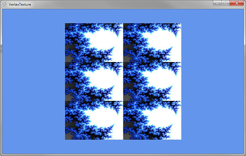
In the previous examples, the texture coordinates ranged from 0 to 1, but you are not limited to just using these values. At times, it is useful for textures to repeat over and over across triangles. For example, you might make a sports game that has a large grass field. Creating a large texture that covers the whole field can be a large memory expense. An option is to have a smaller texture that repeats itself over the field every few feet. The higher number used for the texture coordinates, the more number of times the texture repeats.
There are two ways for the texture to repeat itself. The first is called wrapping, which causes the texture to just start over at the end of the first texture. The second is called mirroring, which causes the texture to reverse each time it is repeated.
To see some examples of texture, update the vertices deceleration.

The important changes are the TextureCoordinate values. Originally, the coordinates were set between 0 and 1 for both the U and V coordinates. You updated the code to set the max U value to 2 and the max V value to 3. This causes the resulting image to repeat two times from left to right and three from top to bottom.
Running the code now produces results similar to Figure 8.6. Notice that the texture wraps two times from left to right and three times from top to bottom.
Figure 8.6. Drawing a textured quad with texture wrapping
The texture sampler uses wrapping because you set that in the effect file. If you update the sampler to use mirroring, you see different results.
Update the sampler in the effect file to use the following code:
sampler ColorTextureSampler : register(s0) = sampler_state
{
Texture = (ColorTexture);
MinFilter = Linear;
MagFilter = Linear;
MipFilter = Linear;
AddressU = Mirror;
AddressV = Mirror;
};
You changed both the AddressU and AddressV modes to Mirror. The texture now displays in reverse on every other repeat of the texture.
Running the code now produces a mirroring effect and looks like Figure 8.7.
Figure 8.7. Drawing a textured quad with texture mirroring

Lighting
To produce more realistic 3D objects, you need to add simulated lighting and shading to the objects you are drawing. There are many different types of lighting models that simulate how light works in the real world. Simulated lighting models have to strike a balance between realism and performance. Many of the lighting models used within 3D graphics are not based on how light physically works in the real world; instead, the models try to simulate how the light looks reflected off different types of objects.
We look at some of the common lighting models that are used in 3D graphics including those used in the built-in BasicEffect.
Ambient Lighting
The simple light to simulate is light that has no general direction and has a constant intensity in all directions on an object. This light is scattered many times meaning it has bounced off many other objects before hitting the final object you are shading.
In the real world, this type of light occurs when you are outside but in the shade. Although you are not in the direct sunlight, there is plenty of light that bounces around off other objects to light you and your sounding objects.
In 3D graphics, ambient lighting is used to give the lowest possible level of lighting an object can have in your scene when it is not lit by other types of lighting. The light value is represented by a Vector3 that describes the color in three colors: red, green, and blue using the X, Y, and Z properties. A value of 0 means no light, and a value of 1 means it is fully lit, which is not likely for your ambient light.
To see how ambient lighting looks when used in a game, let’s create a sample that displays four objects: a cylinder, a sphere, a torus, and a flat plane on the ground. You use these objects through your lighting examples while you continually add different types of lighting to the example.
The first step is to add the following member variables to your game class:
Effect ambientEffect;
Model model;
Matrix[] modelTransforms;
Matrix world;
Matrix view;
Matrix projection;
// This is both the light color and the light intensity
Vector3 ambientLightColor;
// The color of the objects you are going to draw
Vector3[] diffuseColor;
The ambientEffect variable stores your custom effect. Update the name of the effect variable in each of the examples with the type of lighting you are using. The next two variables, model and modelTransforms, are used to store the Model and transform hierarchy for the ModelMesh’s contained within the Model.
The next three Matrix values are used to store the matrices to transform the vertices of the Model from local space into screen projection space.
The final two variables are used for the lighting calculations. The ambientLightColor represents the light color and intensity of the ambient light. The diffuseColor array contains the colors for the three objects you plan to draw. This is the color of the object if it was fully lit. Unlike the vertex color example, you set the color to draw the objects by passing the value into the shader as a global constant. If the model contained vertex colors, use those values instead.
Next, in the game’s Initialize method, set the initial values for the previous variables.

First, set the matrices to sensible values to frame the models close to the screen. Then, set the color of the ambient light. Use values of 0.4f or 40 percent. This value is combined with each of the color values set in the next array. Set red, green, blue, and purple values for each of the objects.
Next, load the custom effect file and the model file. In the game’s LoadContent method, add the following lines of code:
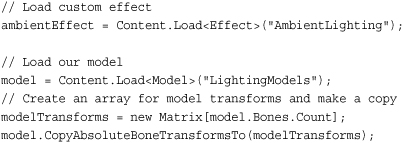
Most of the code should look familiar. You load the Effect file that you will create shortly and a Model that contains the four objects that will display the lighting models. The final two lines of code populate a Matrix array with the local Matrix transforms for each of the MeshParts. Because the fbx file contains multiple objects, they are represented as separate MeshParts, each with its own local Matrix that is used to transform the object into world space.
The final piece of your game code is to update the game’s Draw method with the following code:

Let’s break the code down.
The first variable diffuseIndex is used to offset into the color array to set the color of each of the MeshParts in the Model.
The next section sets the Effect parameters that don’t change over the course of drawing the different parts of the Model. In this case, you set the View and Projection matrix along with the AmbientLightColor. Because setting effect parameters can be expensive, set only new values when you have to. In this case, set them at the highest level and once per use of the Effect.
The next section of code loops over all of the ModelMeshs in the Model. The World matrix is then set by combining the local transform from the ModelMesh with the world matrix for the scene.
The final section of code loops over all the ModelMeshParts within each of the ModelMeshs. Set the VertexBuffer and IndexBuffer, and then set Effect parameters that change per object you draw. In this case, set the color for each object before you call EffectPass.Apply. Each mesh is then drawn by calling DrawIndexedPrimitives.
You have all of the C# game code you need to draw your model using ambient lighting. Now you need to create the custom effect that you need to use with the previous bit of code. Create a new effect file as you have done previously in this chapter and name it AmbientLighting.fx.
Along with the template global variables, add the following global variables:
float3 AmbientLightColor;
float3 DiffuseColor;
These store the ambient light and object color.
Leave the VertexShaderInput and VertexShaderOutput structures as is from the template along with the vertex shader VertexShaderFunction.
Finally, update the pixel shader with the following code:
float4 PixelShaderFunction(VertexShaderOutput input) : COLOR0
{
// Store the final color of the pixel
float3 finalColor = float3(0, 0, 0);
// Add in ambient color value
finalColor += AmbientLightColor * DiffuseColor;
return float4(finalColor, 1);
}
This is a simple pixel shader. It starts by declaring the variable that is used to store the return final color of the pixel. The ambient lighting is then calculated by multiplying the ambient light by the color of the object. The final color is then returned adding the fourth channel for alpha with a value of 1 for fully opaque.
Running this sample should display something similar to Figure 8.8.
Figure 8.8. Ambient lighting
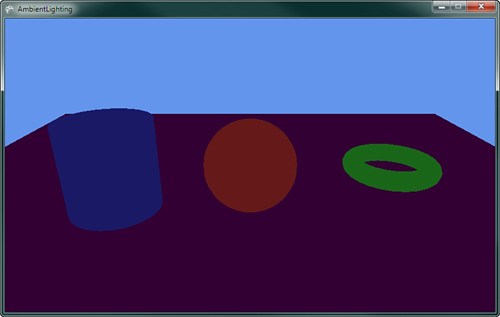
Notice how each of the models is a constant color across the entire mesh. The direction of the triangle is not taken into account with this ambient lighting model.
Triangle Normals
For more realism, take into account the direction the triangle faces in regards to the light. To help determine the direction a triangle is facing, use the normal of the triangle. The normal contains only a direction and, therefore, should always have a length of 1. It is important that you normalize or set the length to 1 of a normal anytime you perform a calculation that alters the normal’s size.
There are two types of normals when working with a triangle. The first is called a face normal and is defined to be perpendicular to the plane that is defined by the three points that make up the triangle. Figure 8.9 shows an example of a face normal.
Figure 8.9. Face normal

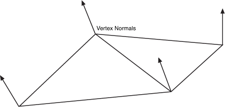
In real-time 3D graphics, the second type of normal called a vertex normal is used. Each vertex of the triangle defines its own normal. This is useful because you might want the object to appear smooth. In this case, the normal at a vertex is averaged with values from adjacent triangles to enable a smooth transition from one to the other. Figure 8.10 shows an example of vertex normals.
Figure 8.10. Vertex normals
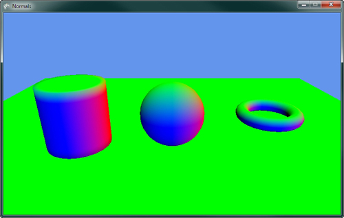
You can update the previous example to display the normal values of the mesh with just a few code changes. No changes need to be made on the game code side, and you need to make only a couple of changes to the shader.
Update the input and output vertex structures to the following:
struct VertexShaderInput
{
float4 Position : POSITION0;
float3 Normal : NORMAL;
};
struct VertexShaderOutput
{
float4 Position : POSITION0;
float3 Normal : TEXCOORD0;
};
The Normal value is added to each structure. The NORMAL semantic used in the input structure tells the graphics card that you want the normal data from the model. It is matched to the corresponding data from the VertexBuffer where the VertexDeceleration has set the normal channel.
Note
The model used in this example contains normal data. This exports from the modeling package used to create the model. If your model does not contain normal data, then you see an exception when you try to draw the model.
In the vertex shader, pass the normal data from the input structure to the output structure. Add the following line of code before you return the output structure:
output.Normal = input.Normal;
The normal data interpolates between each vertex across the triangle for each pixel. In the pixel shader, read this normal value and use the components of the vector as the red, green, and blue color.
Update the pixel shader with the following line of code that returns the normal data as a color:
return float4(normalize(input.Normal), 1);
The normal needs to be normalized because the interpolation can lead to normals with length not equal to 1. The three components of the normal are then combined with an alpha value of 1 to color the pixel. If you run the example, it displays a rainbow of colors similar to Figure 8.11.
Figure 8.11. Geometry colored by their normal values
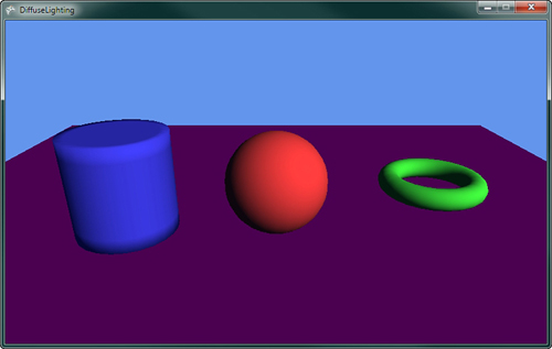
Diffuse Lighting
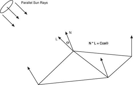
The term diffuse means to scatter or become scattered, so the diffuse light is reflected light that bounces off in many directions causing an object to appear to be flat shaded and not shinny. Ambient lighting, which gives a constant color across the triangles in a mesh diffuse lighting, differs depending on the angle of the triangle to the light source. Use Lambert’s cosine law, which is a common equation used to determine the diffuse color. This law states that the light reflected is proportional to the cosine of the angle between the normal and the light direction.
The type of lighting you are going to model first is called directional light. The light is considered to come from a constant direction in parallel beams of light. This is similar to how sunlight reaches earth.
Note
Sunlight is not parallel but for 3D graphics purposes, it can be treated that way because the size and distance of the sun is so great that the light appears to reach earth as parallel beams.
Because Lambert says you can use the cosine of the angle between the normal and the light, you can easily calculate this by taking the dot product of the normal and the light direction vectors. If both are unit length, then the dot product is equal to the cosine of the angle, which is the value you want.
Figure 8.12 shows the directional lights parallel rays hitting the triangle normals and the angle calculation.
Figure 8.12. Directional light hitting triangle
Let’s add some diffuse lighting from a directional light to the previous example of ambient lighting. The first thing you need are some additional member variables in your game class.
// The direction the light comes from
Vector3 lightDirection;
// The color and intensity of the diffuse light
Vector3 diffuseLightColor;
The first variable lightDirection is exactly what the name describes—the direction the light is going in. There are two ways to describe the direction of a directional light. The first is to describe the direction the light is moving in. This is the way we describe the light in the example. The second is to describe the direction to the source of the light like pointing towards the sun. This is the way you need the value in your shader so you can perform the angle calculation using the dot product.
The second variable is the color of the light. Lights don’t always have to be white; they can be different colors. Each color channel affects the same color channel of the object’s diffuse color.
In your game’s Initialize method, add the following lines of code to set the light’s direction and color. Note that the direction is normalized to keep the vector at unit length.
// Set light starting location
lightDirection = new Vector3(-0.5f, -0.5f, -0.6f);
lightDirection.Normalize();
// Set the lights diffuse color
diffuseLightColor = new Vector3(1, 0.9f, 0.8f);
The final changes you need to make to your game code is to send the values to the Effect. Set the LightDirection and DiffuseLightColor just after the other effect wide parameters as the following code shows. The light direction is negated to change it from pointing from the light to be the direction to the light. This is the format you need in your shader, so make it here instead of calculating the negation multiple times in the shader.

Now, update your custom effect file to calculate the diffuse color in addition to the ambient color.
The first change is to add two new global variables that are used to store the light direction and color.
float3 LightDirection;
float3 DiffuseLightColor;
Like the normal example, add the vertex normal to both the input and output vertex structures.
struct VertexShaderInput
{
float4 Position : POSITION0;
float3 Normal : NORMAL;
};
struct VertexShaderOutput
{
float4 Position : POSITION0;
float3 Normal : TEXCOORD0;
};
The normal values also need to be passed from the input to the output structure in the vertex shader.
output.Normal = mul(input.Normal, World);
Finally, update the pixel shader to calculate the diffuse color and output the color for the pixel. Update the pixel shader with the following code:

First, the pixel shader normalizes the input normal. You need to normalize this value because the interpolation between vertices can lead to the vector not having a unit length. Then, set the minimum value for the diffuse lighting to the ambient light value. This is the minimum that the pixel can be lit. The additional light from the directional light is added to this value.
To calculate the light from the directional light, calculate the value of the dot product of the normal and the light direction. Use the saturate intrinsic function to clamp the value between 0 and 1. If the dot product is negative, then it means the normal is facing away from the light and should not be shaded so you want a value of 0 and not the negative value of the dot product.
The NdotL value is then multiplied by the color of the directional light and added to the diffuse light amount. The diffuse light amount is then multiplied by the diffuse color of the object itself to obtain the final color of the object. The final color is then returned with an alpha value of 1.
If you run the previous code sample, you should see something similar to Figure 8.13.
Figure 8.13. Directional diffuse lighting
Multiple Lights
In the real world, you have more than one light source. You can also have more than one directional light. To add an additional light, add an additional light direction and color to your game class.
// The direction and color of a 2nd light
Vector3 lightDirection2;
Vector3 diffuseLightColor2;
Next, give them some default values in the game’s Initialize method.
// Set the 2nd lights direction and color
lightDirection2 = new Vector3(0.45f, -0.8f, 0.45f);
lightDirection2.Normalize();
diffuseLightColor2 = new Vector3(0.4f, 0.35f, 0.4f);
Then, send the values to the Effect.
diffuseEffect.Parameters["LightDirection2"].SetValue(-lightDirection2);
diffuseEffect.Parameters["DiffuseLightColor2"].SetValue(diffuseLightColor2);
In the shader effect file, add the following two new global variables:
float3 LightDirection2;
float3 DiffuseLightColor2;
In the pixel shader, calculate the dot product of the additional light and add the value to your diffuse light value before adding the value to the finalColor.
// Calculate 2nd diffuse light
NdotL = saturate(dot(normal, LightDirection2));
diffuse += NdotL * DiffuseLightColor2;
Running the example now should show something similar to Figure 8.14.
Figure 8.14. Directional diffuse lighting from two light sources

Oversaturation
As you add more lighting, the possibility of oversaturation becomes a concern. Notice that lighting is additive. As you add more lights, the final color channel values can go above 1, which is full color. As the values go above 1, no change in the final pixel color output the screen occurs. Differences of colors above 1 appear to be the same color to the user. Portions of an object might lose their definition becoming bright white or another solid color. You can limit oversaturation by lowering the amount of lights and keeping the color intensity values of the lights lower. Notice that the previous example used smaller values for the second light’s color. Often, you have one stronger light with an additional couple of weaker lights.
Emissive Lighting
Some objects not only receive light but also give off light. Emissive light is the light given off by the object. The emissive light is added to other light sources.
To add emissive light to the continuing example is quite simple. You need one additional color value for each object you want to draw. Add the following to your game class member variables:
// The emissive color of the objects
Vector3[] emissiveColor;
You will store a separate emissive color for each object like you did for the diffuse color. In the game’s Initialize method, add the following lines of code:
// Set the emissive colors
emissiveColor = new Vector3[4];
emissiveColor[0] = new Vector3(0, 0.75f, 0);
emissiveColor[1] = new Vector3(0, 0, 0.75f);
emissiveColor[2] = new Vector3(0.75f, 0, 0);
emissiveColor[3] = new Vector3(0, 0.75f, 0);
Next, pass this color value into your effect. Just after you set the DiffuseColor, set the EmissiveColor for the effect.
![]()
In the effect file, you need an additional global variable that will store the emissive color.
float3 EmissiveColor;
Finally, in the pixel shader, add the emissive color before you return the finalColor.
// Add in emissive color
finalColor += EmissiveColor;
Running the example now shows the objects with an inner glow of the emissive colors like Figure 8.15.
Figure 8.15. Emissive lighting on the objects
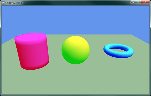
Although the objects look like they are emitting light, they don’t have any effect on other objects. This emissive light is used only on the object itself and does not create a halo around the object.
For the remainder of the chapter, turn off the emissive lighting by setting the emissive color to zero.
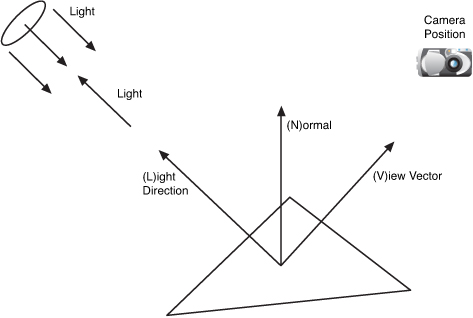
Specular Lighting
In the real world, not all objects are flat shaded. Some objects are shinny and reflect light very well. Think of a bowling ball and how shinny it is. If you look at a bowling ball, notice how there might be bright spots on the ball where the lights in the bowling alley are better reflected.
The shinny spots appear where the angle of the reflected angle from the light about the vertex normal is close to the vector to the camera position. Figure 8.16 shows how the specular light on the triangle is dependent on the viewer angle.
Figure 8.16. Specular light on a triangle
Phong Shading
There are a number of ways to model this shinny appearance of objects. One method is called Phong shading, which is named after its inventor Bui Tuong Phong.
Phong shading uses two new vectors R and V. R is the unit reflection vector of the light about the vertex normal. V is the unit vector of the camera position to the vertex rendered called the viewer vector. The intensity of the specular highlight is then calculated by taking the dot product between R and V. Different materials have different levels of shininess to achieve different results a specular power values are used to raise the R dot V to different powers. This calculated specular intensity value is then multiplied by the object’s specular color and then added to the final color of the pixel.
The equation for the specular shading value using the Phong lighting model is
Specular = (R • V) SpecularPower * (Light Color) * (Object Color)
Blinn-Phong Shading
Calculating the reflection vector requires a number of calculations. To eliminate some of these calculations, Jim Blinn created another specular lighting model based on Phong, called Blinn-Phong in 1977.
Blinn-Phong differs from Phong by using a new vector H called the half vector. The half vector is the vector halfway between the viewer vector V and the light direction L. The half vector can be calculated by adding the view vector V and the light direction L and normalizing the vector to unit length. The H vector is dot multiplied with the vertex normal and raised to a specular power. This is similar to how the R and V vectors are used in the Phong lighting model.
The equation for the specular shading value using the Blinn-Phong lighting model is
Specular = (H • N) SpecularPower * (Light Color) * (Object Color)
Let’s add some Blinn-Phong to the previous example. Add the following member variables to your game:
// The specular color of the objects
// The w component stores the specular power
Vector4[] specularColorPower;
// Specular color of the light
Vector3 specularLightColor;
// The position of the camera
Vector3 cameraPosition;
The first array specularColorPower stores the specular color and specular power for each of the objects. The color uses the X, Y, and Z components of the vector while the W component stores the specular power. The specularLightColor variable stores the specular color of the light source. The final value cameraPosition stores the camera location.
In the game’s Initialize method, add the following values to set the specular color of the objects and the light. Also set the camera position that you used to make the view matrix.
// Set the specular color and power
specularColorPower = new Vector4[4];
specularColorPower[0] = new Vector4(1, 1, 1, 32.0f);
specularColorPower[1] = new Vector4(1, 1, 0, 64.0f);
specularColorPower[2] = new Vector4(0, 1, 1, 32.0f);
specularColorPower[3] = new Vector4(0, 0, 0, 0);
// Set the lights specular color
specularLightColor = new Vector3(1, 0.9f, 0.8f);
// We set the camera position
cameraPosition = new Vector3(0, 1.5f, 3.5f);
These values need to be set on the effect. The SpecularLightColor and CameraPosition can be set with other effect wide properties.
specularEffect.Parameters["SpecularLightColor"].SetValue(specularLightColor);
specularEffect.Parameters["CameraPosition"].SetValue(cameraPosition);
The SpecularColorPower needs to be set with other per object effect values such as the diffuse color.
specularEffect.Parameters["SpecularColorPower"].SetValue(specularColorPower[color Index]);
That is it for the game code changes. Now, you need to update the effect file to add the Blinn-Phong calculations.
First, add some additional global variables to your effect.
float4 SpecularColorPower;
float3 SpecularLightColor;
float3 CameraPosition;
The next change is to the output vertex structure where you add the view vector V, which you calculate in the vertex shader.
struct VertexShaderOutput
{
float4 Position : POSITION0;
float3 Normal : TEXCOORD0;
float3 View : TEXCOORD1;
};
In the vertex shader, the View value is calculated by subtracting the calculated world position from the camera position, which is also in world space.
output.View = CameraPosition - worldPosition;
The final change updates the pixel shader to calculate the specular lighting value and adds it to the final pixel color.

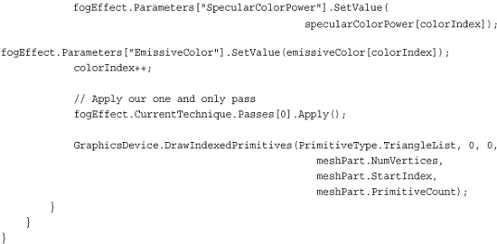
The first line normalizes the View vector, which needs to be unit length and can change as it is interpolated across the triangle. The next line calculates the half vector by adding the view and light direction vectors and then normalizes the result. The dot product of N and H are then taken and clamped between 0 and 1. Finally, its specular value is calculated by using the pow intrinsic function that raises the NdotH value to the specular power, which passed in as the w component of the SpecularColorPower variable and is then multiplied by the light’s specular color.
The last bit of code adds the specular color to the final pixel color using the calculated secular intensity and the object’s specular color stored in the xyz channels of SpecularColorPower.
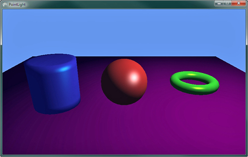
Running the sample now should produce results with a shinny spot on each of the objects in the scene as shown in Figure 8.17.
Figure 8.17. Blinn-Phong specular lighting on objects

Try adjusting all of the lighting and color values in the examples thus far and see how they change the results. Notice that lowering the specular power makes the specular highlight larger but less crisp around its edges.
Fog
Real-world objects that are farther away are not only smaller but also obscured by the amount of atmosphere between the viewer and the object. On most days when the air is clear, the visibility of objects far away are not obscured too much, but on other days a layer of fog might cover the ground lowering the visibility.
In games, you can simulate the fog that obscures objects by interpolating the color of an object as it moves farther into the distance with a fog color. Fog can be any color, but all objects should use a similar fog color; otherwise, some objects will stand out more than others.
There are multiple ways to interpolate the fog value as distance increases. The first method is to use a simple linear interpolation as distance increases. The equation you will use to calculate the linear fog value is
Fog = (Distance – Fog Start) / (Fog End – Fog Start)
The distance is from the camera to the current pixel you are drawing. The fog start is the distance that the fog can start to be seen or where the interpolation should start. The fog end is the distance where the object will be in complete fog. The calculated fog is a floating point value, which is in the range of 0 and 1. Values over 1 should be treated as 1, which means fully in fog. The fog value is then used as the interpolation value of how much of the fog color to use with the final calculated pixel color.
To add linear fog to the ongoing sample, you will add three new member variables to your game.
// Fog color and properties
Vector3 fogColor;
float fogStart;
float fogEnd;
These values store the fog color and distance values you need to send to your custom effect.
These values need to be set to some defaults, so in the game’s Initialize method, add the following lines of code:
// Set fog properties
fogColor = Color.CornflowerBlue.ToVector3();
fogStart = 2;
fogEnd = 18;
Use a color value that is the same as your clear color, so that the objects appear to fade away as they move into the distance. In your game, set the color based on the time of day. If your game is at night, fade to a dark almost black color. If it is daytime, then use a lighter gray color. The fog color can also be used for special effects to simulate some type of toxic gas in a city so you can use some other interesting colors.
The other two values are set to sensible values for the scene. Depending on the size and depth of your scene and the camera’s view, update these values to match the scales.
In the game’s Draw method, send the new values to your custom effect.
fogEffect.Parameters["FogColor"].SetValue(fogColor);
fogEffect.Parameters["FogStart"].SetValue(fogStart);
fogEffect.Parameters["FogEnd"].SetValue(fogEnd);
Finally, update how you are drawing the meshes in sample so that you have many more objects that move farther and farther away from the camera.
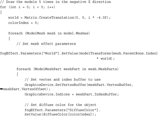
Loop five times to draw the model multiple times and farther and farther depths. This should enable you to get a better idea of the effect of the fog as the distance from the camera increases.
With all of the game code changes complete, you just need to make a few simple changes to your custom effect file to support the linear fog. First, you need the global variables for the fog color and distance properties.
float3 FogColor;
float FogStart;
float FogEnd;
Next, you need to calculate the fog value per vertex, so you need to pass the fog value into the pixel shader. To do this, add the following value to your vertex output structure.
struct VertexShaderOutput
{
float4 Position : POSITION0;
float3 Normal : TEXCOORD0;
float3 View : TEXCOORD1;
float Fog : TEXCOORD2;
};
In the vertex shader, calculate the fog value before outputting the vertex.

Use the same equation described previously. In this code, the distance is calculated by subtracting the world position of the vertex from the camera position. Then, use the length intrinsic function to calculate the length of the resulting vector. The saturate intrinsic function is used to clamp the calculated for value from 0 to 1.
The final change is to update the pixel shader to use the newly calculated fog value. Just before returning the final color from the pixel shader, add the following line of code:
// lerp between the computed final color and the fog color
finalColor = lerp(finalColor, FogColor, input.Fog);
The lerp intrinsic function interpolates between two vectors given the interpolation value, which should be between 0 and 1. Interpolate between the already calculated final color and the fog color depending on the fog value that you calculated in the vertex shader.
Running the sample now should display multiple versions of the models that are farther and farther away from the camera that slowly fade to the background color. This should look similar to Figure 8.18.
Figure 8.18. Objects obscured by fog as they move farther into the distance

The fog value does not have to interpolate linearly with distance. You can also use other types of interpolation such as an exponential falloff to achieve difference results. Because you have the control in the vertex shader, there are many different ways that you can use the distance to calculate the fog value.
Point Lights
All of the examples up to this point use one or more directional lights when calculating the light’s influence on the color of the triangles. Although directional lights work well to simulate the type of light that is coming from distant objects such as the sun, they don’t work to simulate how objects look indoors when lit from multiple smaller artificial lights such as light bulbs. In computer graphics, we call these types of light sources point lights.
Point lights have a known position in 3D space, which differs from directional lights that only have a direction. The direction to the point light must be calculated because it changes depending on the location of the object drawn.
The light that comes from smaller lights like the ones in your home tends to lose its brightness the farther away an object is from the light. You can see this in your home when you turn off the lights in a room and have only a single table lamp to light the room. Notice that the light is brightest close to the lamp, but falls off quickly with distance from the light. This falloff from the light source is called attenuation and differs depending on the size and type of light.
There are multiple ways in which you can calculate the attenuation when simulating the light that comes from point light sources. Use the following attenuation equation:
Attenuation = 1 - (((Light Position - Object Position) / Light Range) * ((Light Position - Object Position) / Light Range))
In the previous equation, the light position is the location of the point light. The object position is the location you are currently drawing in world space, and the light range is how far the light rays will travel from the light source.
To demonstrate how point lights work in the game, update the previous specular lighting example, which uses directional lights.
First, you need some different member variables for the game. Remove the vector that represents the light direction and update it with the following code:
// The position the light
Vector3 lightPosition;
// The range of the light
float lightRange;
The light now has a position and a float value that represents the distance from the light that objects can be lit from.
In the game’s Initialize method, give the point light the following values:
// Set light starting location
lightPosition = new Vector3(0, 2.5f, 2.0f);
// The range the light
lightRange = 6.0f;
In the same location where you set the light direction for the effect in your game’s Draw method, update the effect with the new point light properties.
![]()
Most of the changes to support the point light occur in the effect file. You need two new global variables to store the light position and range.
float3 LightPosition;
float LightRange;
You need the position of the pixel you are rendering in the pixel shader in world space. To do this, add an additional value to the vertex output structure to store the position in world space.
struct VertexShaderOutput
{
float4 Position : POSITION0;
float3 Normal : TEXCOORD0;
float3 View : TEXCOORD1;
float3 WorldPos : TEXCOORD2;
};
The vertex shader needs to be updated to save the calculated world space position of the vertex.
output.WorldPos = worldPosition;
The pixel shader should be updated to the following:

Although it appears to be a lot of code at first, it is actually close to the pixel shader used for the specular lighting example. Let’s walk though the important differences.
The input world position is interpolated for each pixel giving the location of the current pixel in world space, which is what you need to calculate the distance to the light source. The light variable is stored with the vector form the pixel to the light. The attenuation is then calculated using the equation from earlier in the chapter. The light vector is then normalized because you use this value as the direction of the light as you would if this was a directional light. The new normalized light is then used in the calculations of NdotL and half. Finally the attenuation is multiplied when calculating the diffuse and specular intensity values.
Running the sample now shows the objects in the scene lit from a point location where the light falls off the farther the objects are away from the light. Rotating the light or moving the light source from each frame can make this much more visible. Figure 8.19 shows the objects in the scene lit from a single point light.
Figure 8.19. Objects lit by a point light source
Adding multiple point lights works in a similar way as adding additional directional lights. The lighting influence of each additional light source needs to be calculated for each light and added into the diffuse and specular intensity values. You can also mix and match by supporting a directional light and point lights in your effect.
Effect States
Chapter 7 discusses setting the different device states using the different state objects. Changing these states requires your game code to create different state objects and to set them on the device.
Effect files have the capability to also set these states within their effect pass blocks. When your game calls EffectPass.Apply, if the effect pass contains any state changes, then they will be set on the device.
The default effect file template that is used when you create a new effect file in XNA Game Studio add a nice comment to let you know where you can set render states in the effect pass.

There are many different states that can be set and the naming of the states and their values defers from the XNA Game Studio state objects. A listing of all of the states and values that are supported by an HLSL effect can be found at the following link:
http://msdn.microsoft.com/en-us/library/bb173347(VS.85).aspx
Note
XNA Game Studio limits some states and values that can be set in order to conform to the Reach and HiDef graphics profiles. This validation occurs when the effect file is built using the content pipeline. Reading any error from the build informs you of any states that are not supported in XNA Game Studio.
Alpha Blending Using Effect States
You can create an example of how to utilize the effect states by creating a custom effect that uses alpha blending to render the transparent objects. You utilize the existing specular sample that you created previously.
First, load a different model to draw. You use a model that has three separate objects that are close together so that when you make them transparent, you will see through each of them into the others. Update the LoadContent method with the following line of code. Also, add the model to your content project.
// Load our model
model = Content.Load<Model>("AlphaDemo");
To display the models with some transparency, update the diffuse colors to contain an extra alpha channel. The diffuseColor array needs to be updated to a Vector4 from the current Vector3. Then in the Initialize method, update the diffuseColor array with the following values:
// Set the diffuse colors
diffuseColor = new Vector4[3];
diffuseColor[0] = new Vector4(1, 0.25f, 0.25f, 0.25f);
diffuseColor[1] = new Vector4(0.25f, 1, 0.25f, 0.5f);
diffuseColor[2] = new Vector4(0.25f, 0.25f, 1, 0.7f);
Unlink previous effects from this chapter—the effect you will create has multiple passes. This means that you will draw the geometry of the models multiple times, once for each EffectPass. Update the section of the Draw method, which calls Apply on the EffectPass and draws the primitives that make up the model with the following.

Because you have more than one pass, loop over all of the passes calling Apply and then drawing the indexed primitives that make up the ModelMeshPart you are currently drawing.
Now in the effect file, you need only a few small changes. The first is to update the pixel shader to use the w component of your diffuse color for the transparency value of the pixel.
// return the final color
return float4(finalColor, DiffuseColor.w);
Now, update the existing effect pass and add another.
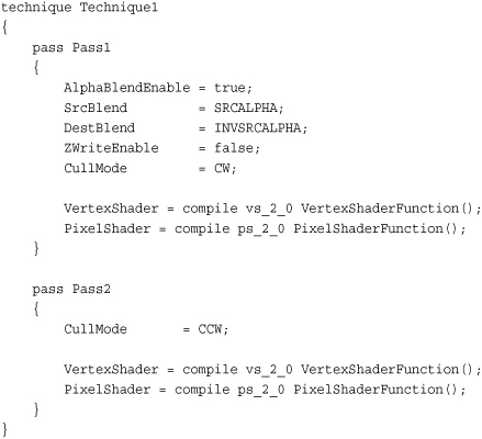
Because you draw 3D models with transparency and you want to be able to see through them, you want to see the inside of the back of the object. Although you normally cull the backward facing triangles, update the cull mode to clockwise so that you will draw the inside triangles. The first effect pass also sets the normal alpha blending states. In the second effect pass, the cull mode is set back to the default counterclockwise so that you can draw the front-facing triangles. If you didn’t draw the inside of the objects or you drew the front first, the blending would not look correct if you want the objects to appear to be transparent and to have volume.
The states set by the effect file persists until they are changed either by state objects in the game code or by another effect pass, which defines the state.
Running the sample now displays two spheres with a cylinder between them. Figure 8.20 shows the three objects and how the different transparencies among them enables you to see through the objects to what is behind them.
Figure 8.20. Effect states used to draw multiple models with alpha blending

Summary
In this chapter, we covered the basics of creating your own effect files from the different parts of the effect file including the pixel shader, vertex shader, and the techniques and passes. We also covered how to use both vertex colors and textures to color the triangles you draw.
An introduction to different lighting models was covered with numerous samples that built on each other to create useful lighting effects.
Finally, effect states were discussed and how they can be used instead of state objects in your game code to set render states.
This chapter contained many examples in which can be found in the accompanying code files that can be downloaded for this book.
Now that you have a better understanding of what custom effects are and how to use them, you should be able to develop your own effects and be able to better understand other types of shading techniques.