Chapter 4. Introduction to 3D Graphics
Let’s face it—graphics are cool. Graphics are a major reason why many developers become interested in gaming technology and creating games. The capability to create an image that can change over time is impressive. 3D graphics gives a false since of depth to an image on a flat 2D surface.
In this chapter, you learn:
• What makes up 3D graphics
• Basic mathematics used in 3D graphics
• Stages of the graphics pipeline
• Graphics profiles
• Using the GraphicsDevice and GraphicsAdapter objects
• Drawing each of the primitive types
3D Graphics in XNA Game Studio
Developing 3D graphics is similar to creating real-time art. Even more impressive are the detailed and interactive 3D graphics found in modern real-time computer games. It is impressive when you compare it against computer graphics of ten years ago. Console and PC games were limited to a fixed set of hardware features, and resolutions were quite low and far from today’s high resolution, multisampled, antialiased, and almost realistic images.
With all of the new fancy hardware-dependent graphical improvements of the past decade also came an increase in complexity when creating graphics for games. Developers deal with many complexities, even when drawing simple graphics on the screen.
XNA Game Studio has attempted to limit these complexities in some cases and in others to solve them all together. As discussed in previous chapters, the capability to have a basic graphics window display a clear color is trivial and requires only that you create a new project for one of the supported platforms. To get to that point, using C++ with DirectX or OpenGL can take hundreds of lines of code. The graphics APIs exposed by XNA Game Studio are easy to use and often lead to the developer to fall into the correct solution using them.
Note
If you have used XNA Game Studio before, you will notice a number of API differences in XNA Game Studio 4.0. A tremendous amount of work and energy went into updating the graphics APIs to be even easier to use and to support the new Windows Phone 7 platform.
In this chapter, we cover the basics developers should know before diving into creating 3D graphics. We start with defining 3D graphics and their makeup. Then, we focus on some basic math that is required when working on 3D graphics. Next, we cover the different stages that are part of the graphics pipeline. We finish by covering the XNA Game Studio GraphicsAdapter and GraphicsDevice classes and drawing the first 3D primitives on the screen.
What Are 3D Graphics?
The answer to this question might seem simple, but it might not be obvious to those who have no experience creating 3D games or applications. In reality, 3D graphics are just an illusion. They are flat 2D images on a computer monitor, television screen, or phone display.
In the real world, your eyes work together to create an image that contains visual perspective. Objects appear to be smaller the farther they are away from you physically. Imagine you are standing in the middle of perfectly straight and flat railroad tracks. If you look down at your feet, the rails appear to be some distance apart. As you let your eyes move towards the horizon and look farther down the tracks, it appears that the track rails become closer to each other the farther they are away from you. Having two eyes adds to this depth perception because each eye has a slightly different view. They help to see slightly different angles of objects. This difference is even greater for objects near to you. If you alternate closing each eye, you see objects move left and right.
When you create 3D graphics, perspective is an illusion. When you are working with 3D graphics concepts, remember that you are really creating a 2D image that is displayed on the screen. Many parts of the graphics pipeline have nothing to do with 3D at all and work only on the pixel level. A friend of mine once described to me a helpful way to look at developing 3D graphics games. He related creating 3D graphics to how great painters create stunningly realistic pieces of art. Although to a viewer standing still the painting can appear to represent real 3D objects in the world, it is still just layers of paint on flat canvas. They are illusions just like computer-generated 3D graphics.
So what are 3D graphics? They are computer-generated images that give the appearance of depth and perspective, but in reality, they are just flat 2D images when displayed.
Makeup of a 3D Image
In a Chapter 2, “Sprites and 2D Graphics”, we described how sprite textures are used to draw 2D images on the screen. You can think of this concept as placing stickers on the screen and moving them around.
3D graphics images are generated differently. At their core, they are a bunch of triangles drawn on the screen. If this sounds simplistic, it is in order to be fast. Modern graphics hardware can be so fast because the types of operations it performs are limited when compared to general-purpose processors used for CPUs in PCs. Graphics hardware has dedicated hardware for these operations and are designed to process millions of triangle and pixel operations.
Groups of triangles drawn on the screen are commonly called geometry. These collections of geometry can represent almost anything from a box, to a space ship, to a human marine storming the beaches of Normandy.
Each triangle is made up of three vertices. Each vertex represents one of the corners of the triangle and must contain at least the position of itself. A vertex can also contain other data such as color, texture coordinates, normals, and so on.
Although triangles determine the shape of what is displayed on the screen, there are many factors that determine the final color of pixels the triangle covers on the screen. Some of those factors such as texturing, lighting, and blending are covered in Chapter 6, “Built-In Shader Effects” and Chapter 7, “States, Blending, and Textures.”
2D Sprites Are Actually in 3D!
When you draw 2D sprites in XNA Game Studio, you use the 3D graphics pipeline. In the past, 2D graphics were drawn using a technique called blitting, which was copying memory from a surface such as a texture to the display memory. With today’s graphics cards, it is easier and faster to just draw two-textured triangles when you want to draw a texture on the screen. Because sprites are also 3D geometry, many of the topics in this chapter are also applicable to them.
3D Math Basics
Those who are new to 3D graphics might ask the question, “Do I need to know math to create 3D graphics?” The simple answer is “Yes, there is a level of mathematics that is required when you are working on a 3D game.” Can you get by without knowing much? Absolutely, and we have seen many examples where people have created a 3D game but don’t necessarily understand how they are getting the results they see. This often leads to questions such as, “Why is my model orbiting around the camera when I wanted it to rotate on its axis like a planet?”
Without a doubt, having a better understanding of underlying mathematics leads you to be less confused, more quickly understand new concepts, and be more productive.
This section attempts to strike a balance of theory and practical use. The goal is to give you the higher level concepts that are used throughout 3D graphics without having to explain the details of how to do specific mathematical operations such as vector arithmetic or matrix multiplication. There are countless educational sources on these operations, and they are already implemented in the math types provided in XNA Game Studio. We spend our time focusing on what these operations mean geometrically and how they are used within 3D graphics.
Coordinate Systems
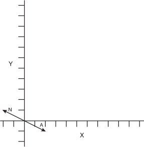
We already used one type of coordinate system, which were screen coordinates when drawing sprites on the screen. In screen coordinate space, there are two dimensions: one for each of the X and Y directions. In screen coordinates, the X direction increases in value from the left side of the screen to the right, and the Y increases in value from the top of the screen to the bottom.
There are two main types of 3D coordinate systems used in computer graphics. These two different types differ in direction from the positive Z points relative to the X and Y axes. The two types of coordinate systems are called right-handed and left-handed (see Figure 4.1). Both of these systems contain three directions for the X,Y, and Z axes. The three axes converge at a central point called the origin where their values equal 0. The values along each axis either gain or lower in value at regular intervals depending on whether you are moving in the positive or negative direction along that axis.
Figure 4.1. Left- and right-handed coordinate systems

To visualize these two different coordinate systems, let’s do a quick exercise. Take your right hand and make a fist. Turn your hand so your bent fingers face you and the top of your hand faces away from you. Now, extend your thumb. It should point directly to your right. Your thumb represents the positive X axis. Now extend your index finger, also known as your pointer finger, directly up in the air. This represents the positive Y direction. Your hand should look like it is making a capital L now with your thumb facing right and representing the positive X axis and your index finger pointing upwards representing the positive Y axis. Finally, extend your middle finger and point it directly at yourself. Your middle finger represents the positive Z axis (see Figure 4.2).
Figure 4.2. Right fist forming the right-handed coordinate system
Imagine lines that extend from the tips of all three of your fingers; they should be 90 degrees apart from each other forming right angles between themselves. Having each axis be at right angles from each other creates what is called an orthogonal coordinate system. In this case, you created a right-handed coordinate system. This is the coordinate system used by default in XNA Game Studio. In a right-handed coordinate system, the negative Z axis is used for the forward direction.
Note
DirectX by default uses a left-handed coordinate system. The properties and methods in XNA Game Studio assume you are using a right-handed coordinate system. Some methods also provide a left-handed equivalent for those who want to use a left-handed system.
To visualize a left-handed system, follow the previous instruction except face your palm away from yourself but still make a capital L with your thumb and index finger for the positive X and Y axes. Now when you extend your middle finger to form the positive Z axis, notice that it now points away from you. In a left-handed coordinate system, the positive Z axis is used for the forward direction (see Figure 4.3).
Figure 4.3. Left fist forming the left-handed coordinate system

Note
Although we just stated that Z axis is used for the forward direction, this is not always true. In some 3D art creation packages, the Z axis actually represents the up direction. The good news is that this difference is accounted for when XNA Game Studio loads models from those specific 3D content packages.
Vectors in 3D Graphics
A vector is a mathematical geometric construct that consists of multidimensional values that provide a magnitude and direction. That sounded a little too much like a math class. You can think of vectors as a set of floating point values used to represent a point or direction in space. Use groups of vectors to represent the triangles that make up the geometry in your game.
You have already used vectors in Chapter 2, “Sprites and 2D Graphics.” The Vector2 type, which contains two float values for X and Y is used to express the position to draw the sprites. XNA Game Studio also provides Vector3 and Vector4 types, which contain three and four components each.
XNA Game Studio uses free vectors. Free vectors are represented by a single set of components equal to the number of dimensions of the vector. This single set of components is able to express a direction and a magnitude. By contrast, in mathematics, another type of vector exists called a bounded vector, which is represented by two sets of components for both the start point and the end point. Because they are not often used in computer graphics, we focus on free vectors, which we call just “vectors.”
What Units Are Vectors In?
Vectors are in whatever unit you want them to be in. The important rule is to be consistent throughout your game and even your art pipeline. If one artist creates buildings for your game and one unit equals a meter, and another artist creates your game characters with one unit equaling one inch, the buildings are going to look small or your characters are going to look big. If you are working on a team, it is helpful to decide on what one unit is equal to in your game.
If you are not able to author or export your art content yourself, the content pipeline scales your models for you given a scaling factor.
Vector4 the Four Dimensional Vector
As we mentioned, XNA Game Studio supports three types of vectors: Vector2, Vector3, and Vector4. Vector2 has two dimensions, so use it in 2D graphics. Vector3 has three dimensions, and is used it in 3D graphics. What should Vector4 be used in?
A Vector4 like the Vector3 type contains the X, Y, and Z values. The fourth component, called the homogeneous component and represented by the W property, is not used for space time manipulation unfortunately. The fourth component is required when multiplying the vector by a matrix, which has four rows of values. Matrices and vector multiplication are discussed later in this chapter.
Point Versus Direction and Magnitude
When working with Vector3 and Vector4 values, they can represent a 3D point in space or a direction with a magnitude. When you use a vector as the vertex position of a triangle, it represents a point in space. When a vector is used to store the velocity of an object, it represents a direction and a magnitude. The magnitude of a vector is also commonly referred to as the length of the vector and can be accessed using the Length property of all of the vector types.
It is often useful to have a vector that represents a direction and magnitude to have a length of 1. This type of vector is called a unit vector. Unit vectors have nice mathematical properties in that they simplify many of the equations used with vectors so that their operations can be faster, which is important when creating real-time graphics in games. When you change a vector, so its direction stays the same but the length of the vector is set to one, it is called normalizing the vector. A Normalize method is provided for each of the vector types.
Vector Addition
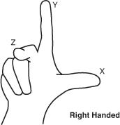
When you add two vectors A and B together, you obtain a third vector C, which contains the addition of each of the vector components. Vector addition, like normal algebraic addition, is commutative meaning that A + B is equal to B + A.
Geometrically vector addition is described as moving the tail of the B vector, which is at the origin, to the head of the A vector, which is the value the A vector represents in space. The resulting vector C is the vector from the tail of A, which is the origin, to the head of B.
In Figure 4.4, vector A contains a value of { 2, 1 } and vector B contains a value of { 1, 3 }. The resulting vector C contains the value { 3, 4 }.
Figure 4.4. Example of vector addition
If any of the components of the vector are negative, the values are added together in the same way. The resulting value can have negative components.
Vector Subtraction
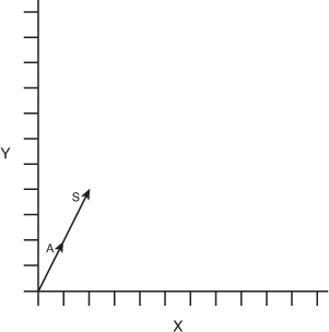
When you subtract two vectors A and B from each other, you obtain a third vector C, which is the difference of each of the vector components. Vector subtraction is not commutative meaning that A – B is not equal to B – A.
Geometrically vector subtraction is described as moving the head of vector B to the head of the A vector. The resulting vector C is formed from the tail of A, which is at the origin, to the tail of B.
In Figure 4.5, vector A contains a value of { 3, 4 } and vector B contains a value of { 1, 3 }. The resulting vector C contains the value { 2, 1 }.
Figure 4.5. Example of vector subtraction

Vector Scalar Multiplication
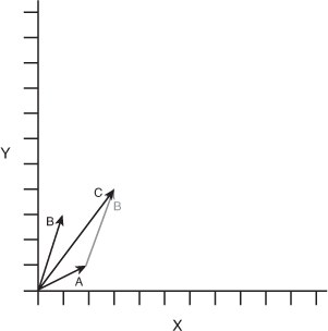
Vectors can be multiplied by a single number called a scalar. This scalar value is multiplied against each component to produce a new vector with the same direction but whose length has been multiplied by the scalar.
Geometrically the multiplication of a vector by a scalar can be described as taking the original vector and stretching or shrinking the length by the scalar value.
In Figure 4.6, vector A has a value of { 1, 2 }. When multiplied by the scalar of 2, the new vector S has a value of { 2, 4 }.
Figure 4.6. Example of vector scalar multiplication
Vector Negation
To negate a vector, each of the component’s signs are changed to the opposite. Positive components become negative and negative components become positive. This is the same as multiplying the vector by a value of negative one. The negation of a vector is often written –A, where A is the vector name. Each of the vector types contains a method called Negate, which returns the negation of the given vector.
Geometrically the negation of a vector represents a vector in the opposite direction with the same length.
In Figure 4.7, vector A has a value of { 2, -1 }. When negated, it produces vector N, which has the value { -2, 1 }.
Figure 4.7. Example of vector negation
Vector Dot Product
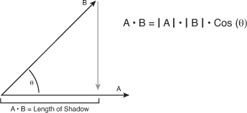
The dot product, also called the scalar product, creates a scalar value from multiplying each of the vector components with each other and adding the results together. The dot product is written in the form A • B, pronounced as A dot B. The resulting scalar value is equal to the cosine of the angle times the length of A times the length of B. As we mentioned before, using normalized vectors simplifies some linear algebra equations, and this is one of them. To determine the angle between two vectors, first normalize each of the vectors. Then, take the dot product to return the cosine of the angle. Use the arccosine to find the angle value in radians.
Geometrically you can think of the dot product of two vectors A and B as the length of vector A in the direction of vector B. Because the vector dot product is commutative, it has the same value as the length of vector B in the direction of vector A. This of this as one vector casting a shadow onto the other vector.
In Figure 4.8, the dot product A • B is both a scalar value related to the angle between the vectors as well as the length of vector A in the direction of vector B.
Figure 4.8. Example of vector dot product
Vector Cross Product
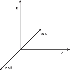
The vector cross product of vectors A and B produce a resulting vector C that is perpendicular to the plane that both A and B are located on. The cross product is commonly written as A × B pronounced A cross B. The cross product is helpful when building orthonormalized coordinate spaces. As we discussed, 3D coordinate spaces contain three unit vectors for the X,Y, and Z axis. Each of these unit vectors can be created by taking the cross product of the other two axes. The Z axis is created from the result of X cross Y. Y from Z cross X. X from Y cross Z. The cross product is not commutative nor is it associative, so A × B is not equal to B × A. Taking the cross product of B × A produces a perpendicular vector that is the negation of A × B.
In Figure 4.9, notice that vectors A × B produces a perpendicular vector C while B × A produces a vector equal to –C.
Figure 4.9. Example of vector cross product
Vectors in XNA Game Studio
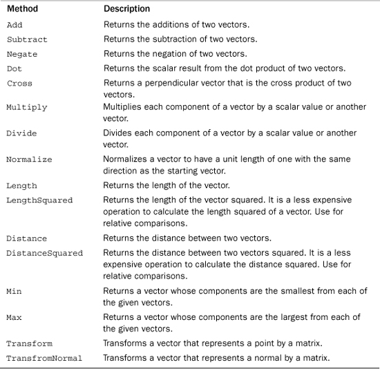
The vector types in XNA Game Studio provide a number of helpful properties and methods to perform the calculations we have been discussing and more that we cover throughout this book. Tables 4.1, 4.2, and 4.3 contain the fields, properties, and methods of the Vector3 type. The Vector2 and Vector4 types have similar fields, properties, and methods.
Table 4.1. Fields of Vector3

Table 4.2. Properties of Vector3
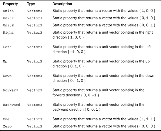
Table 4.3. Abbreviated Table of Vector3 Methods
Note
Many of the math methods provided in XNA Game Studio provide overloads, which take the parameters as references and return the result as an out parameter. Using these versions of the methods can save the overhead of many copies of the structures passed to the method. Use these versions in your time-critical sections of your game where you have performance problems.
Matrix
In mathematics, a matrix is rectangle group of numbers called elements. The size of the matrix is expressed in the number of rows by the number of columns. In 3D graphics, the most common type of matrix is the 4 by 4 matrix, which contains 16 float values. The XNA Game Studio Matrix structure is a 4 by 4 matrix. A matrix has a number of mathematical applications in a number of fields including calculus and optics. For our purposes, we focus on the use of a matrix in linear algebra because of how useful this becomes in computer graphics.
In computer graphics, the matrix is used to represent linear transformations, which are used to transform vectors. These linear transformations include translation, rotation, scaling, shearing, and projection. The elements of the matrix create their own coordinate spaces by defining the direction of the X,Y, and Z directions along with the translation from the origin. Using a matrix that is 4 by 4 in size enables all of the linear transforms to be combined into a single matrix that is used to transform position and direction vectors.
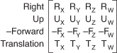
In XNA Game Studio, the matrix structure is row major meaning that the vectors that make up the X,Y, and Z directions and the translation vector are laid out in each row of the matrix. Each row represents a different direction in the coordinate space defined by the matrix.
In the first row, the X vector represents the right vector of the coordinate space. In the second row, the Y vector represents the up vector of the coordinate space. In the third row, the Z vector represents the backward vector of the coordinate space. The forward vector is actually the negation of the Z vector because in a right-handed coordinate space, the Z direction points backwards. The forth row contains the vector to use for the translation of the position. Figure 4.10 shows the vector components of a matrix.
Figure 4.10. Vector components of a matrix
Many of the transforms produce what is called an orthogonal matrix where the X,Y, and Z directions are all 90 degrees from each other. In addition there are some transforms, which contain both orthogonal and normalized direction vectors producing an orthonormalized matrix.
Identity
The identity matrix, also called the unit matrix, contains elements with the value of one from the top left diagonal down to the bottom right. The rest of the elements in the matrix are all zeros (see Figure 4.11).
Figure 4.11. Identity matrix

When the identity matrix is multiplied by any other matrix, the result is always the original matrix (see Figure 4.12).
Figure 4.12. Identity matrix multiply

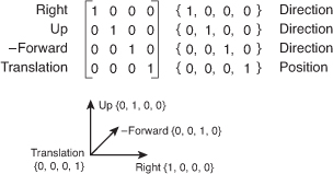
The identity matrix is an orthonormalized matrix that defines the unit directions for X,Y, and Z for the unit coordinate space (see Figure 4.13).
Figure 4.13. Right-handed unit coordinate space
The identity matrix is a base starting point for many of the other types of transforms.
Translation
A translation matrix is a type of matrix that is used to translate or move a vector from one location to another. For example if a vector contains the values { 1, 2, 3 }, a translation of { 2, 1, 0 } moves the vector to { 3, 3, 3 }.
In a translation matrix, the last row contains the values to translate by (see Figure 4.14).
Figure 4.14. Translation matrix

When a vector is multiplied by a translation matrix, the result is a vector with a value equaling the original vector’s value plus the translation of the matrix.
Rotation
A rotation matrix transforms a vector by rotating it. Rotation matrices come in the form of rotations around the X,Y, or Z axes along with rotation around an arbitrary axis. Each type of rotation matrix has its own element layout for defining the rotation. Figures 4.15, 4.16, and 4.17 show the different types of axis rotation matrices.
Figure 4.15. X axis rotation matrix
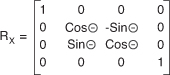
Figure 4.16. Y axis rotation matrix
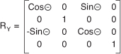
Figure 4.17. Z axis rotation matrix

When a vector is multiplied by a rotation matrix, the resulting vector’s value is equal to the original vector value rotated around the defined axis.
In XNA Game Studio, the creation of rotation matrices is as simple as calling one of the static methods provided by the Matrix structure, such as CreateRotationX. The specified angles are in radian units. In radians, 2 Pi units is equal to 360 degrees. Pi is a mathematical constant, which is the ratio of a circle’s circumference to the diameter of the circle. The value of Pi is around 3.14159. To convert between radians and degrees, use the MathHelper.ToRadians and MathHelper.ToDegrees methods.
Rotations are sometimes referred to in terms of yaw, pitch, and roll. These represent rotations around the current coordinate spaces right, up, and forward vectors, which are not necessarily the same as the unit X,Y, and Z axes. For example, if an object is already rotated 45 degrees around the Y axis, the forward vector is not in the negative Z direction anymore. It is now halfway between negative Z and negative X (see Figure 4.18).
Figure 4.18. Yaw, pitch, and roll vectors for an oriented object

Rotating this object around the X axis is not the same as rotating around the pitch vector, because the pitch vector no longer is equal to the unit X vector.
Scale
A scale matrix transforms a vector by scaling the components of the vector. Like the identity matrix, the scale matrix uses only the elements in the diagonal direction from top left to lower right. The rest of the elements are all zeros (see Figure 4.19).
Figure 4.19. Scale matrix

When a vector is multiplied by a scale matrix, each component in the vector is scaled by a corresponding element in the matrix. A scale matrix does not have to be uniform in all directions. Nonuniform scale is also possible where some axis directions are scaled more or less than others.
Combining Matrix Transforms
Matrices cannot only be multiplied with vectors to transform them, but can also be combined together to form a new linear transform. The resulting matrix can then be used to transform the vector. The combined transforms on the vector have the same effect as multiplying each against the vector in succession.
Multiple matrices are combined to create a complex transform that is finally multiplied with the vector. This is beneficial when you are transforming thousands of vectors that represent the vertices of triangles in geometry. The resulting combined matrix needs to be calculated only once and can be used for all of the geometry.
When multiplying two matrices A by B, the number of columns in the first matrix A has to equal the number of rows in matrix B. In XNA Game Studio, this is not a concern because the Matrix structure is 4 by 4 square.
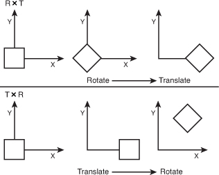
Matrix multiplication is not commutative meaning that A × B is not the same as B × A, which makes sense if you think about it geometrically. If you have a rotation matrix R and multiply it by a translation matrix T, the resulting matrix first rotates an object and then translates the object. If you reverse the order, the object first translates and then rotates causing the object to orbit. The order you combine matrices is important. In general, you want to first scale, then rotate, and finally translate (see Figure 4.20).
Figure 4.20. Results of multiplying by rotation and translation matrices in both orders
Manipulating Vectors with Matrices
Matrices are useful in transforming vectors. As we have discussed, vectors can be used for position data for things like the position of triangles that make up geometry in the game or they can be used for directions for things like the direction and velocity a car is moving. Transforming these two types of vectors occurs slightly differently and has to do with the fourth component of the vector, the homogeneous W component.
As we discussed, 4 by 4 matrices are used because they have the capability to hold multiple types of linear transforms in a single matrix. To be able to multiply a vector by a matrix, the number of components of the vector must equal the number of rows of the matrix. The fourth row of the matrix holds the translation of the matrix.
For vectors that represent position, it is important that the translation of the matrix affects the vector that is multiplied. Because of this, the W component of vectors that represent positions should have a value of 1. This enables the matrix multiply to include the affect of the translation elements of the matrix.
For vectors that represent a direction and magnitude, they should not be translated when multiplied by a matrix. Because of this, the W component of the vectors that represent direction vectors should have a value of 0. This enables the matrix multiply to not allow the translation of the matrix to affect the vector.
Often in your game, you will not want to store your position and direction vectors as Vector4 types. Storing these values as a Vector3 saves you the memory of an extra float component. It also saves you the trouble of having to set the W component. To determine whether the vector is used for position or as a direction, the Vector3 structure provides two transform methods. The first called Transfrom takes a matrix and expects the input value to be a position vector. It expands the Vector3 into a Vector4, sets the W component to 1, and then multiplies the input vector by the matrix returning the resulting vector as a Vector3 after dropping the added W component. The other method TransformNormal works in the same way except it expects a direction vector and sets the W component to 0. Tables 4.4, 4.5, and 4.6 contain the fields, properties, and methods of the Matrix type.

Table 4.5. Properties of Matrix

Table 4.6. Abbreviated Table of Matrix Methods

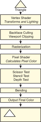
Graphics Pipeline
The graphics pipeline is the set of operations that occur from when you request to draw some geometry that turns the triangles into pixels drawn on the screen or other render target. It is important to understand what is occurring in the pipeline so you can achieve the graphical results you desire. We briefly cover the important stages of the pipeline to give you a good idea about how triangles turn into pixels (see Figure 4.21). As we progress, some of the stages are covered in more detail.
Figure 4.21. High-level graphics pipeline from triangle to pixels on the screen
Graphics Card
With today’s technology, almost all the graphics’ pipeline computations occur in a specialized piece of hardware called a graphics card. Graphics cards contain a specialized processor called the graphics processing unit (GPU).
Graphics cards became popular towards the end of the 1990s when 3D computer games became more popular. Today, most PC computers contain some type of GPU. Sometimes the GPU is integrated onto the main motherboard of the machine.
There are several types of graphics cards on the market today. Having so many different graphics cards to support becomes a problem when trying to write games and other applications that want to utilize the hardware. 3D graphics APIs, like those exposed by the XNA Game Studio, enable developers to program their code once and have that code run in a similar manner across many different graphics cards.
Although the XNA Game Studio provides a single API set to communicate with several graphics cards, the behavior among these cards can vary greatly from card to card. To solve this problem, XNA Game Studio 4.0 introduced the concept of graphics profiles. Graphics profiles are discussed later in this chapter.
Vertex Shader
After you request to draw the triangles that make up an object, such as a teapot, each of these triangles are sent individually to the vertex shader. The vertex shader is a small program run on the graphics hardware that is responsible for transforming the triangle positions from the 3D model space they were defined in into a projected screen space so they can be drawn as pixels. The vertex shader is also responsible for calculating lighting values for the triangle that are used when determining the final color to output pixel color.
The vertex shader is programmable and controlled by creating a small vertex program that is compiled and set to the graphics hardware. Creating your own custom vertex shaders are covered in Chapter 8, “Introduction to Custom Effects”.
World Transform
World space defines where the geometry is translated, how it is rotated, and how much it is scaled. All of these are linear transforms from their defined positions in model space.
To move from model space to world space, a world matrix is used to transform the vectors that make up the triangles in the geometry. Each set of geometry that make up objects in your game, like the teapot, generally have their own world matrix that translates, rotates, and scales the object.
View Transform
The geometry is now positioned in the world, but where the viewer is located? View space determines where the 3D scene is viewed from. Often it is helpful to think of view space as the view from a camera in the scene.
To move from world space to view space, a view matrix is used to transform the geometry. There are different types of view matrices that cause the scene to be viewed in different ways. Typically your scene utilizes one view matrix for all of your geometry. For more information on the view matrix, see Chapter 5, “Lights, Camera, Action.”
Projection Transform
The final step is to take the 3D scene and project the scene onto a 2D plane so it can be drawn on the screen. This is called projection space or clip space.
To move from view space to projection space, a projection matrix is used to transform the geometry. For more information on the different types of project matrices, see Chapter 5.
Backface Culling
To cull something means to remove something that is useless. When drawing real-time computer graphics, speed is always a consideration. The 3D graphics’ pipeline is designed to be fast and efficient. One of the optimizations that occurs in the graphics pipeline is to remove triangles that face away from the viewer in a process called backface culling.
In most cases, when drawing triangles, they can be seen only from one side. When looking at a teapot made of triangles, you would not want to draw the triangles that were on the far side facing away from you. These triangles are covered by the closer front-facing triangles on the front of the teapot.
So the question is how does the graphics pipeline know which triangles are front facing and which are not? This is set by something called winding order. By default, triangle vertices are defined in clockwise order in XNA Game Studio. Counter-clockwise triangles are culled and do not continue to other operations down the graphics pipeline.
You might not want triangles’ backfaces culled for things such as a road sign. The GraphicsDevice.RasterizerState enables you to set CullMode values to turn off backface culling or change it to cull clockwise triangles.
Viewport Clipping
The front-facing vertices of the triangles still contain four values for X,Y, Z, and the homogeneous W component. Before continuing further down the graphics pipeline, the X,Y, and Z components of the vertex are divided by the homogeneous W component to return the vertex to three dimensions. This process is called the homogeneous divide.
The next optimization is to determine whether any part of the triangle is visable on the screen. Triangle vertices with values of X and Y between –1 to 1 and a Z value of 0 to 1 are visible on the screen and should continue down the graphics pipeline.
Triangles that are partly on the screen are clipped. This means that only the visible part of the triangle continues to the next stage of the pipeline while the part that is off the screen is culled away. Triangles that don’t have any viable part on the screen are culled entirely.
Note
Although the graphics hardware removes geometry that is not visible, it is often a performance for games with several objects to do some type of higher level culling, such as frustum culling, before drawing objects to the scene.
Rasterization
The next stage, rasterisation, is the process of converting the triangles into the individual pixels that are used on the screen. Triangles don’t always fall directly over a pixel. If a triangle covers the center of the pixel, then the pixel is considered covered by the triangle.
Note
There are several complex rules over which pixel is shaded by which triangle and how to determine which triangle to use when two triangle edges share the same pixel. This is a more advanced topic that is not covered in this book. In most cases, it won’t matter to you.
Pixel Shader
The triangles have now been broken down into a set of pixels. Each of these pixels are now sent to the pixel shader. The pixel shader is a small program run on the graphics hardware that takes the pixel’s position and determines the pixels output color. The output color can be anything from a solid color to a complex color calculated from lighting values.
The pixel shader is programmable and controlled by creating a small pixel program that is compiled and set to the graphics hardware. Creating your own custom pixel shaders are covered in Chapter 8.
Pixel Tests
Although you calculated the output pixel color from the pixel shader, it can still be thrown away. There are several pixel tests that could cause the pixel to be invalid and not used.
Scissor
The scissor test enables you to set a rectangle region within the screen to draw to. If you want to limit rendering to a small section of the screen, you can set the GraphicsDevice.ScissorRectangle property to a rectangle within the screen bounds and set the ScissorTestEnable property of the GraphicsDevice.RasterizerState to true. By default, the scissor test is not enabled.
Stencil
The next test is called the stencil test. Stencil tests utilize a special buffer called the stencil buffer, which, if enabled, contains eight bits of data per pixel on the screen. When drawing geometry, the stencil value can be incremented, decremented, or not changed. This value can then be used to test future pixels to determine whether they pass the stencil test.
In most common cases, you do not change the stencil values or use the stencil test when drawing objects on the screen. Stencil tests are used for more advanced rendering techniques like stencil shadows and portal rendering.
Depth
The last test and one of the most important is the depth test. The depth test utilizes a special buffer called the depth buffer also called a Z buffer, which can contain 16 or 24 bits of data per pixel. The depth test is used to determine whether a pixel is in front or in back of other pixel’s draw to the same location.
Consider the case where you draw the teapot on the table. If you look down on the teapot and draw an imaginary line through the teapot and through the table, it hits a number of triangles for a number of pixels.
How do you determine which triangle is in front of which? A depth buffer works by storing the depth Z value of the last triangle drawn to a specific pixel. When the next triangle that uses the same pixel is about to be drawn, the depth value of that triangle is compared to the value stored in the depth buffer. If the value of the new triangle is lower, the pixel color continues down the graphics pipeline and the new Z value is stored in the depth buffer. If the value is higher, the new pixel is behind a pixel that was already drawn and can be thrown out if the depth test is enabled.
Blending
Although the final color for the pixels that make up the triangles being drawn are determined, this does not mean this is the desired color to be draw on the screen. A number of blending operations can occur between the source color from the pixel shader and any colors already draw on the screen.
For more information on the different blending operations, see Chapter 7, “States, Blending, and Textures.”
Final Output
The final step in the pipeline is to store the color value. In most cases, this is stored on the screen in what is called the backbuffer, which is discussed later in this chapter.
It is also possible to draw directly onto a texture using a render target. After you complete a drawing to a render target, use it like any other texture in your game. Render targets are discussed in Chapter 7.
Reach and HiDef Graphics Profiles
Before we talk about how to utilize the XNA Game Studio graphic types to draw our first triangles on the screen, we need to talk about one of the new changes that XNA Game Studio brings to graphics.
Graphics Profiles Define Platform Capabilities
In the beginning of this chapter, we discuss how developing 3D games can be complex. One of the large complexities has to do with how to handle different graphics hardware on different platforms. Different graphics cards support slightly different capabilities. This is especially a problem on the PC where there are many different types of graphics cards. In the past, developers had to query the graphics card for its capabilities and then make decisions about what types of graphics operations to use based on those stated capabilities. There were hundreds of capabilities and they were difficult to test because you needed all of the different types of graphics hardware accessible to you.
To solve this problem, XNA Game Studio 4.0 introduced the concept of a GraphicsProfile. A graphics profile sets specific requirements that a particular piece of hardware meets or it doesn’t. If a particular piece of hardware supports a profile, then all of the features in that profile are supported. As a developer, you set the target GraphicsProfile. XNA Game Studio 4.0 supports two graphics profiles called Reach and HiDef.
When your application starts on a machine that does not support every aspect of that profile, a NoSuitableGraphicsDeviceException exception is thrown and enables you to inform the user that he or she can’t run your game.
At development time, the graphics APIs in XNA Game Studio enforce the GraphicsProfile you selected. For example, the Reach profile supports textures with width and height up to 2048 while the HiDef profile supports up to 4096. If your game targets the Reach profile, an exception is raised if you attempt to create a texture larger than 2048 even if the PC you are developing on could support the HiDef profile. Having the APIs respect the GraphicsProfile setting ensures you do not use features that are not supported and your game runs on any platform that supports the Reach profile.
The Reach Profile
As the name implies, the Reach profile provides the capability to give your game title reach meaning that the code and content you create for your game would work on a large number of platforms and systems. The Reach profile is supported by Windows Phone 7 devices, the Xbox 360, and Windows PCs with a DirectX 9 GPU that support shader model 2.0 or higher.
The HiDef Profile
The HiDef profile was designed for systems that provide more advanced graphics capabilities. This limits the number of platforms and systems that support the profile but allow for a richer set of capabilities. The HiDef profile is a superset of the Reach profile meaning that any platform and system that can support the HiDef profile by definition also supports the Reach profile. The HiDef profile is supported on the Xbox 360 and Windows PCs with a DirectX 10 or equivalent GPU.
So what does equivalent mean? It means that some DirectX 9 hardware is also supported but must meet some specific capabilities. The list of capabilities is too long and of little importance to cover in this book.
Note
A chart comparing the differences between the profiles including specific details such as texture size limitations can be found in the appendix.
Determining GraphicsProfile Support
To find out whether your graphics card supports either of these two profiles, create a simple Windows application and call the GraphicsAdapter.IsProfileSupported method passing in a specific graphics profile.
Let the 3D Rendering Start
Now that we covered the basics of the graphics pipeline and some of the math that is involved, let’s see how these concepts relate to the types exposed by XNA Game Studio and draw some triangles on the screen.
GraphicsAdapter
Use the GraphicsAdapter class to enumerate and update graphics adapters. Most single monitor PCs have one graphics adapter that represents their physical graphics card and the one connection it has to the monitor. Some graphics cards provide two graphics adapters so you can plug two monitors into a single graphics card. In this case, the GraphicsAdapter allows for selecting two different adapters so you can display the graphics on two different monitors. The Xbox 360 and Windows Phone devices provide only one GraphicsAdapter.
The static GraphicsAdapter.DefaultAdapter property returns the default adapter in which there are multiple adapters to chose from. For example, when you set the left monitor to be the primary display in Windows, the DefaultAdapter property returns the GraphicsAdapter to display graphics on the left monitor.
The static GraphicsAdapter.Adapters property returns a read-only collection of the adapters available. You rarely need to enumerate graphics adapters. Most commercial PC games provide a settings page that enables the user to select the adapter so he or she can change which display to view the game. This is required when the game runs in full screen and the user does not have the normal window controls to click and drag.
If your game uses windowed mode, the user can click and draw the window to the other monitor. Although this changes the GraphicsAdapter used, all of this is handled for the user by XNA Game Studio by default.
Note
If you developed games using a native graphics API before and tried to support monitor dragging and toggling between windowed and full-screen modes, you know the trouble to get it working properly.
The GraphicsAdapter provides several properties and methods that enable you to determine what type of graphics card is available and what the capabilities of the graphics card are.
The QueryBackBufferFormat and QueryRenderTargetFormat methods can be used to determine whether a specific back buffer or render target format is supported. We discuss back buffers and render targets later in this chapter.
The DeviceName, Description, DeviceId, VendorId, SubSystemId, and Revision properties are used to return information about a specific GraphicsAdapter to determine whether the graphics card is a specific model from a specific manufacturer. They also enable you to determine what the current driver version is.
Note
A graphics driver is a piece of software that enables the operating system to communicate with the graphics hardware. Graphics card manufacturers create the driver to instruct the operating system on how to perform specific tasks with the hardware.
Each GraphicsAdapter can support a number of display modes. Just as you can set your PC to use different resolutions, your game can use different resolutions. The SupportedDisplayModes returns a collection of DisplayMode structures. Each structure contains properties for the Width, Height, and Format for the display mode. A display format is defied using the SurfaceFormat enumeration. The format defines how each pixel on the screen is represented in terms of the data that is stored at each pixel. The most common format, SurfaceFormat.Color, is a 32-bit value that stores four channels of red, green, blue, and the alpha each with 8 bits of value.
Note
Alpha is a term used to express how transparent a color is. We cover transparency and alpha in Chapter 7.
The DisplayMode structure also provides two helper properties called AspectRatio and TitleSafeArea. The AspectRatio is the value you get when you divide the width of the display by the height of the display. This is often calculated when working with 3D graphics and is sometimes calculated incorrectly. The property gives you a simple way to retrieve the value without having to calculate the value each time you need it.
When drawing to televisions, they have outer edges of the screen cut off. If you draw to the top left corner of the screen and display this on a number of televisions, you will notice that each television has a slightly different position of where the top left corner is. The TitleSafeArea defines where you should limit drawing game specific graphics such as text and the heads up display for a character. Using the property ensures that your graphics are visible across different televisions.
GraphicsDevice
The GraphicsDevice in your game is responsible for issuing the drawing commands down to the driver, which then goes through the graphics pipeline. The GraphicsDevice is also responsible for loading graphics resources such as textures and shaders.
Every GraphicsDevice contains a back buffer. The back buffer is the data buffer where the graphics that ultimately end up displayed on your monitor are drawn to. It is called the back buffer because it is not displayed on the screen. What you see displayed on the screen is actually the contents of what is called the front buffer. Drawing occurs to the back buffer, so you don’t see each piece of geometry appear on the screen as it is drawn. After all of the draw calls are performed in a single frame, the GraphicsDevice.Present method is called, which flips the front and back buffers to display the contents of the back buffer.
Along with a width and height, the back buffer also has a SurfaceFormat, which defines the bit layout and use for each pixel in the back buffer. As we discussed, the GraphicsAdapter can be used to determine what formats are available. The most common is the Color format.
If a back buffer resolution that is smaller than the display is requested on the Xbox 360 or on a Windows Phone, the final image is up scaled to fit the screen. If the aspect ratio is different, then the display black bars are displayed on the top and bottom of the screen called letterboxing or on the sides of the screen called pillarboxing to fill out the extra space.
When calling the Present method, you specify a PresentInterval. The present interval is used to determine when the flip of the front and back buffers occur. Displays on computer monitors, televisions, and phone screens all have a refresh rate. The refresh rate is the speed that the displays update their physical screen commonly between 30Hrz to 60Hrz. When displays update, they do so by updating line by line until the entire screen is updated. At that time, the display performs a vertical retrace sometimes referred to as a vblank. This is when the screen is moving from the end of where it is currently updating to the start again. If the front and back buffers are flipped in the middle of the display, updating a graphical artifact called tearing can occur. Tearing is where part of the displayed screen shows one frame while another portion displays another. This occurs if the flip is not in sync with the vertical retrace because you change what is drawn on the screen in the middle of the display updating the display. To prevent this, the flip should occur during the vertical retrace.
When you set the PresentInterval, you have three options of when the flip between the front and back buffers occurs. If PresentInterval.One is used, the buffers wait to flip until the display is in the vertical retrace phase. This means the fastest your graphics can update is the same speed as your display’s refresh rate. PresentInterval.Two is used only to flip the buffers every other vertical retrace. PresentInterval.Immediate can be used to perform the flip as soon as possible and not wait for the vertical retrace. Although your game can suffer from tearing artifacts, this mode is helpful when performing performance analysis because it does not limit the speed at which your game can draw.
Along with the back buffer, a GraphicsDevice can also contain another buffer called the depth buffer. The depth buffer is used to store the depth values of a triangle when the color of that triangle is written to the back buffer. The values are used in the depth test position of the graphics pipeline that we discussed previously. A depth buffer can have three types of formats specified by the DepthFormat enumeration. The first is Depth16, which stores a 16-bit floating point value at each pixel. Depth24 provides a 24-bit floating point number to store depth at each pixel. Finally, the Depth24Stencil8 format provides the same 24 bits for depth but also enables another 8 bits to be used by the stencil buffer. The stencil buffer is used in the stencil test portion of the graphics pipeline.
Creating the GraphicsDevice
Although it is possible to create the graphics device yourself using the GraphicsDevice constructor, this is not needed when using Game class because the default template creates a GraphicsDeviceManager, which creates the GraphicsDevice.
If you want to change any of the default values that the GraphicsDeviceManager uses to create the graphics device, you can use code similar to the following in your Game class constructor.

The GraphicsDeviceManager.SupportedOrientations can be used to define which orientations you want your game to support. This is useful for Windows Phone games where the user can flip the physical phone device and might do so because of the requirements of the game. If you elect to support an orientation when the user rotates the phone, the screen flips to support the new orientation. For example, if you want to support a landscape game where the user can play the game by rotating the phone to the left or right, use the following lines of code:
![]()
Now when the user rotates the phone from one horizontal position to the other, the display automatically flips and your game appears correctly for the new orientation.
Reference Devices
There is a special type of graphics device called a reference device also known as ref device. A reference device does not use the graphics hardware and implements all of the graphics functionally in software on the computer’s CPU. A reference device can be used when the graphics hardware does not support some specific graphics feature. The downside is that the reference device is tremendously slow compared to graphics hardware.
Drawing with Primitives
If you have never developed 3D graphics applications, this is where you become a graphics developer for the first time. All of the geometry that we draw in future chapters builds upon the following primitive drawing.
Primitive Types
XNA Game Studio supports four types of primitives defined by the PrimitiveType enumeration: TriangleList, TriangleStrip, LineList, and LineStrip. A TriangleList is a list of triangles just like its name implies. Every three vertices are treated as a new triangle meaning that each triangle requires three vertices to be stored. In most cases, this is overkill because most triangles are directly next to another triangle. With a TriangleStrip, the last three vertices are used to draw the next triangle. For example, you can draw two triangles with only four vertices. The first three vertices make up the first triangle and the last vertex is used in conjunction with the last two vertices from the first triangle to form the second triangle. Using triangle strips helps reduce the amount of memory required to store the vertices of triangles. The TriangleStrip is by far the most common PrimitiveType used.
The ListList is similar to the triangle list except that only two points are needed to form a single line. Every two points creates a new line segment. The LineStrip is similar to a triangle strip except that only the last point from the previous line segment is needed to form another line.
Vertex Types
Each vertex that makes up the triangle contains the position data for where the triangle is in space, but it can also contain other data such as the color that the triangle should be, texture coordinates for textured triangles, or normal data for lighting calculations. XNA Game Studio provides several ways to build in vertex types that can be used when defining your triangles or lines. You can also create your own vertex types for more complex rendering scenarios.
Drawing Primitives
There are ways to render geometric primitives in XNA Game Studio. All four methods are provided by the GraphicsDevice class. The first two methods—DrawUserPrimitives and DrawUserIndexedPrimitives—both work by specifying an array of vertices and a primitive type to the GraphicsDevice, which, in turn, draws the primitives.
The second two methods—DrawPrimitives and DrawIndexedPrimitives—use vertices that have been stored on the graphics hardware. Storing vertex data directly on the graphics hardware lowers drawing latency because the data needed to draw the geometry is already in memory in the graphics hardware near where the computations are occurring.
Along with vertex data, the two indexed methods—DrawUserIndexedPrimitives and DrawIndexedPrimitives—also use index values that are used to index into the vertex data. Instead of using the vertex data directly to draw the primitive, indexed vertices are defined using an offset into the vertex data. This saves space when multiple primitives use the same vertex.
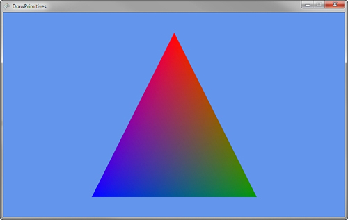
DrawUserPrimitives
The easiest way to draw a primitive on the screen is to declare an array of vertices and pass these to the DrawUserPrimitive method. Along with the vertices, we create an instance of BasicEffect. We cover effects and how they work in Chapter 6, “Built-In Shader Effects.” For now, you know that the effect is needed so the graphics hardware knows what to do in the vertex shader and pixel shader portions of the graphics pipeline.
Define the following member variables in your Game class:
VertexPositionColor[] userPrimitives;
BasicEffect basicEffect;
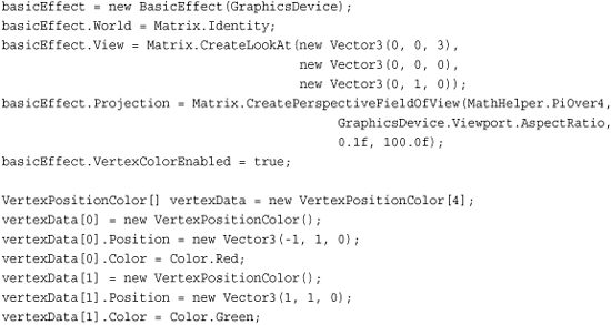
Next, define the vertices and create a new instance of BasicEffect and set some of the properties. Add the following lines of code in your Game class LoadContent method:

In the previous code, you define three vertices of type VertexPositionColor. This vertex type holds a position and color for each vertex. You define the position and color for the top, right, and left vertices. The order you specify these is important because order is not culled by default in XNA Game Studio.
After you create your vertices, you create an instance of BasicEffect. The World, View, and Projection properties are used in the vertex shader portion of the graphics pipeline to transform the input vertices to draw on the screen. For now, don’t worry about the specific values for these matrices. The VertexColorEnabled property is set to true to tell the BasicEffect to use the color from each vertex as the output value of the pixel shader.
The final step is to issue the draw call using the DrawUserPrimitives method. Add the following lines of code to your Game class Draw method:

Before you can call DrawUserPrimitives, tell the GraphicsDevice to use the BasicEffect. This is done by calling Apply on the EffectPass you use. EffectPass is covered in Chapter 8, “Introduction to Custom Effects.”
Next, call DrawUserPrimitives. This method is generic and expects the vertex type as the generic T type parameter. In this case, pass VertexPositionColor as the vertex type. The first parameter defines what PrimitiveType you want to draw. Specify TriangleList to draw a list of triangles. The second parameter is an array of vertices of the same type used for the generic T parameter. Pass the userPrimitives array you created previously. The third parameter is used to specify an offset into the array of vertices. If your array contains multiple primitive vertices and you want to draw only a subset of those, you can specify an offset into the source array. For your purpose, you don’t want any offset, so set the value to 0. The final parameter DrawUserPrimitives takes the total number of primitives to draw. If your array defines multiple primitives, specify that number to draw with this parameter. For this example, you draw only a single triangle, so specify a value of 1.
If you build and run the previous example, you should see a single triangle like that in Figure 4.22. Notice that each vertex has its own color. and the color of the middle sections of the triangle change across the triangle to each vertex. This is called interpolation and occurs on values that are specified per vertex. Because the color is specified per vertex, the different vertex colors have to interpolate over the pixels between the two vertices.
Figure 4.22. Using DrawUserPrimitives to draw a single triangle

Now let’s update the example to draw multiple primitives using the LineStrip primitive. First, update where the vertices are created with the following lines of code:
// Create the verticies for our lines
userPrimitives = new VertexPositionColor[4];
userPrimitives[0] = new VertexPositionColor();
userPrimitives[0].Position = new Vector3(-1, 1, 0);
userPrimitives[0].Color = Color.White;
userPrimitives[1] = new VertexPositionColor();
userPrimitives[1].Position = new Vector3(-1, -1, 0);
userPrimitives[1].Color = Color.White;
userPrimitives[2] = new VertexPositionColor();
userPrimitives[2].Position = new Vector3(1, 1, 0);
userPrimitives[2].Color = Color.White;
userPrimitives[3] = new VertexPositionColor();
userPrimitives[3].Position = new Vector3(1, -1, 0);
userPrimitives[3].Color = Color.White;
Note
The lines are set to Color.White to help make them more visible. You can use any color just like you would for triangles.
Then, update your DrawUserPrimitives call to specify the LineStrip primitive type and the new number of primitives:
// Draw the primitives
GraphicsDevice.DrawUserPrimitives<VertexPositionColor>(PrimitiveType.LineStrip,
userPrimitives, 0, 3);
If you run the example now, it should look like Figure 4.23.
Figure 4.23. Using DrawUserPrimitives to draw a LineStrip

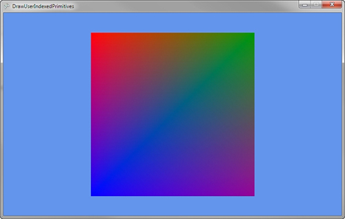
DrawUserIndexedPrimitives
If your primitives commonly use the same vertices for a number of different primitives, it can save you memory to use indexed primitives instead. To draw a user indexed primitive, you need to specify an array of indexes to use when drawing the triangles. These index values are used to look up each specific vertex to use when rendering the primitive.
To draw a user indexed primitive, update the current example. Add an array of index value. These are integer values that represent offsets into the vertex array you also pass into the DrawUserIndexedPrimitives method. Update the member variables for your Game class to have the additional index array like the following code:
VertexPositionColor[] userPrimitives;
short[] userPrimitivesIndices;
BasicEffect basicEffect;
Use a 16-bit short array to store the index values. Because each index is represented by a short, the index values can be between only 0 and 65535, which is the maximum positive number a short can represent. You can also use an array of 32-bit int values, which can store positive values of more than four billion but this has two repercussions. The first is that storing index values as int values means that each index takes up two more bytes than when using shorts thus doubling the memory usage for your index values. The other is that 32-bit int indexes are supported only in the HiDef GraphicsProfile, so your game must usea HiDef GraphicsDevice.
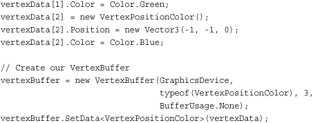
Next, create the vertices and index values for your primitives. In this case, draw a square, often called a quad, that is made of two triangles. Update the existing example’s LoadContent method to contain the following code:
// Create the verticies for our triangle
userPrimitives = new VertexPositionColor[4];
userPrimitives[0] = new VertexPositionColor();
userPrimitives[0].Position = new Vector3(-1, 1, 0);
userPrimitives[0].Color = Color.Red;
userPrimitives[1] = new VertexPositionColor();
userPrimitives[1].Position = new Vector3(1, 1, 0);
userPrimitives[1].Color = Color.Green;
userPrimitives[2] = new VertexPositionColor();
userPrimitives[2].Position = new Vector3(-1, -1, 0);
userPrimitives[2].Color = Color.Blue;
userPrimitives[3] = new VertexPositionColor();
userPrimitives[3].Position = new Vector3(1, -1, 0);
userPrimitives[3].Color = Color.Purple;
// Create the indices used for each triangle
userPrimitivesIndices = new short[6];
// First Triangle
userPrimitivesIndices[0] = 0;
userPrimitivesIndices[1] = 1;
userPrimitivesIndices[2] = 2;
// Second Trianglel
userPrimitivesIndices[3] = 1;
userPrimitivesIndices[4] = 3;
userPrimitivesIndices[5] = 2;
Like the previous example, create an array of VertexPositionColor to represent the vertices in your primitives. The code creates four vertices: one for each corner of the quad. A short array is then created to specify which vertex to use for each primitive. The first triangle uses the top left, top right, and bottom left vertices making sure to define them in clockwise order. The second triangle uses the top right, bottom right, and bottom left.
Finally, update your Game class Draw method to use the DrawUserIndexPrimitives method:
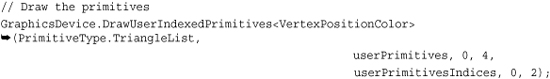
Like the previous example with DrawUserPrimitives, the DrawUserIndexedPrimitives call is generic and you pass the VertexPositionColor as the generic T type parameter. The first parameter is again the primitive type. The second parameter is again the array of vertices. The third parameter is the vertex offset that should be used. For index primitives, this offset is added to each index value to obtain the final index to use in the vertex array. The fourth parameter is the number of vertices that is used in the draw call. In this case, use four vertices. This parameter is often the size of the vertex array itself unless you use offsets. The fifth parameter is the array used to store the index values. For the example, that is the userPrimitivesIndices variable. The sixth parameter is the offset into the index array that should be used. In this case, you don’t need to offset, so the value is 0. The final parameter is again the number of primitives to draw. For the example, you try two triangles, so a value of 2 is specified.
If you build and run the example code, you should see an image like that in Figure 4.24 where a four-color quad is draw on the screen.
Figure 4.24. Using DrawUserIndexedPrimitives to draw a quad
Let’s lower the memory used by the index array by updating the example to just use four index values and use the TriangleStrip PrimitiveType. Update where you create the index array to look like the following:
// Create the indices used for each triangle
userPrimitivesIndices = new short[6];
// First triangle
userPrimitivesIndices[0] = 0;
userPrimitivesIndices[1] = 1;
userPrimitivesIndices[2] = 2;
// Second Triangle
userPrimitivesIndices[3] = 3;
The second triangle is formed by using the last two index values plus the new additional value. In this case, the triangle is formed by userPrimitivesIndices[3], userPrimitivesIndices[2], and userPrimitivesIndices[1]. This second triangle saves 32 bits of data by not using two additional index values.
The DrawUserIndexedPrimitives method call needs to be updated to use only PrimitiveType.TriangleStrip and not TriangleList. If you run the example code now, you will not see any visible difference yet you are saving valuable memory space. It is not always possible to save space and use triangle strips; in these cases, you should use TriangleLists.
DrawPrimitives
Unlike the user versions of the draw primitives methods that use arrays to store the vertex data, DrawPrimitive uses a VertexBuffer to store the vertices for your primitives.
A VertexBuffer stores the vertices in the graphics cards hardware memory where they can be quickly accessed. Unlike when using arrays, a VertexBuffer does not require the vertices to be sent from the main system memory to the graphics card each time you want to draw. Sending large amounts of data from the main system memory to the graphics card is not a fast operation and can slow down your rendering speed. So for larger geometry, use a VertexBuffer to store the vertex data and to call the DrawPrimitives method.
First, create two member variables in your Game class: one for the VertexBuffer and another for the BasicEffect. Add the following lines of code to create the member variables:
VertexBuffer vertexBuffer;
BasicEffect basicEffect;
Next, create the VertexBuffer and set the data that is stored inside it. Add the following lines of code to your Game class LoadContent method:

As with the previous example, you first create an instance of BasicEffect and set some of the properties for the transforms and enable vertex coloring.
Again, declare an array of VertexPositionColor and define three vertices. Use this array to set the data to store in the VertexBuffer.
Next, create the instance of the VertexBuffer. The VertexBuffer takes the GraphicsDevice to store the data as the first parameter. Use the GraphicsDevice property of the Game class to use the default GraphicsDevice that is created when your game starts. The second parameter takes the Type of the vertex that is to be stored in the VertexBuffer. Because you want to store vertices of type VertexPositionColor, specify the type using the typeof operator. The third parameter is the number of vertices the VertexBuffer is going to hold. In this case, there are only three vertices. The fourth and final parameter is the BufferUsage. In cases where you know you will never need to read the contents of the VertexBuffer, you can specify BufferUsage.WriteOnly, which causes the VertexBuffer to throw an exception if you ever try to read back any data. Using WriteOnly enables the graphics hardware to chose specific memory locations in the hardware that allow for more efficient drawing.
After the VertexBuffer is created, the SetData method is called to send the vertex data to the graphics hardware. SetData is a generic method that takes the type of vertex data as the generic T parameter. The array of vertices is then passed as the lone parameter. The size of the VertexBuffer must be large enough to store the amount of vertices stored in the array that is passed in. Overloaded versions of SetData are available that enable you to specify an offset, start index, number of vertices to set, and the size of each vertex. These overloads are useful when the source vertex array is slit into multiple vertex buffers.
The final steps you need to draw are to tell the GraphicsDevice the VertexBuffer you plan to use next and to call the DrawPrimitives method. Add the following lines of code to your Game class Draw method:
// Set which vertex buffer to use
GraphicsDevice.SetVertexBuffer(vertexBuffer);
// Set which effect to use
basicEffect.CurrentTechnique.Passes[0].Apply();
// Draw the triangle using the vertex buffer
GraphicsDevice.DrawPrimitives(PrimitiveType.TriangleList, 0, 1);
The GraphicsDevice is told which VertexBuffer to use by calling the SetVertexBuffer method and passing in the one you created. This is the VertexBuffer that is used when any DrawPrimitives or DrawIndexPrimitives methods are called until another VertexBuffer is set on the GraphicsDevice. Overloads of SetVertexBuffer are available that enable an offset into the VertexBuffer to be specified.
Next, the EffectPass.Apply method is called like in the previous example.
Finally, call the DrawPrimitives method. The first parameter is the PrimitiveType. The second parameter is the start vertex. This is the vertex in the buffer to start drawing from. This value is combined with any offset value set when SetVertexBuffer is called. The final parameter is the number of primitives to draw, which you set to 1 because you need to draw only the single triangle.
If you run the previous example code, you see output similar to Figure 4.25. Notice how this example and the first example that used DrawUserPrimitives produced the same results but use different functions to draw the primitives.
Figure 4.25. Using DrawPrimitives to draw a triangle
DrawIndexedPrimitives
The final draw primitives called DrawIndexedPrimitives uses both a VertexBuffer and an IndexBuffer. Like a VertexBuffer, the IndexBuffer stores data using the graphics hardware’s memory so it can be quickly accessed by the GPU when drawing. The IndexBuffer stores index values like the ones you used previously when using the DrawUserIndexPrimitives method.
To draw indexed primitives using an index buffer, add a member variable to your Game class to hold the instances of the IndexBuffer, VertexBuffer, and BasicEffect.
VertexBuffer vertexBuffer;
IndexBuffer indexBuffer;
BasicEffect basicEffect;
Next, create the index data to store in the IndexBuffer and create the instance of the IndexBuffer. Also create the VertexBuffer and BasicEffect as you did previously:
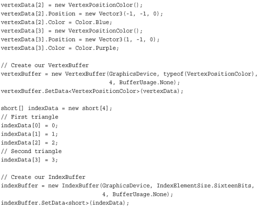
In the previous code, you create an array of shorts to store the index values. Because you use a triangle strip, you need only four index values. The IndexBuffer is then created. The first parameter is the GraphicsDevice where the IndexBuffer is stored. The second parameter is the size each element in the index buffer is. Remember that index values can be 16-bit short values or 32-bit int values. You select IndexElementSize.SixteenBits to specify that 16-bit index values. The fourth parameter is the number of index values the IndexBuffer holds. You specify 4 the size of your index data array. The last parameter is BufferUsage, which is similar to the same parameter on the VertexBuffer. You specify None, which will enables read back if necessary later.
Finally, tell the GraphicsDevice which IndexBuffer to use when the DrawIndexPrimitives method is called. Add the following lines of code to your Game class Draw method:
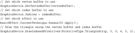
As with the previous examples, you set the VertexBuffer to use and call Apply on the EffectPass you want to use. You also specify the Indices parameter of the GraphicsDevice setting its value to your IndexBuffer. The DrawIndexedPrimitives method is then called to draw a quad on the screen. Like all of the other draw methods, the first parameter is the PrimitveType, which, in this case, is a TriangleStrip. The second parameter is the base vertex, which is an offset that is added to each of the values in the index buffer. The third parameter is the minimum vertex index of all of the vertices used. The fourth parameter is the number of vertices that are going to be used when drawing the triangles. The fifth parameter is the starting index to use in the index buffer. The last parameter like the other draw methods is the number of primitives to draw.
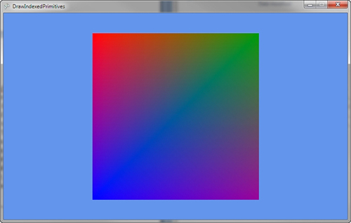
If you run the example code, you should see a colored quad similar to the one in Figure 4.26.
Figure 4.26. Using DrawIndexedPrimitives to draw a quad
Summary
It is time to take a deep breath. We covered a lot of information about 3D graphics in this chapter including what 3D graphics is in regards to interactive games and applications, some of the basic mathematics needed to work with 3D graphics, an overview of the graphics pipeline, and finally how to draw some geometry on the screen using the four main drawing methods provided by XNA Game Studio.