Chapter 12. IPv6 BGP for Service Providers
The following topics are covered in this chapter:
![]() IPv6 BGP Features and Concepts
IPv6 BGP Features and Concepts
![]() IOS XR BGP Policy Accounting
IOS XR BGP Policy Accounting
![]() 6PE
6PE
![]() 6VPE
6VPE
IPv6 BGP Features and Concepts
Routing protocols and features have expanded for IPv6 over the years. A great number of improvements and features have been added for BGP’s support of IPv6 as well. Although most of BGP’s features and behavior is the same between IPv4 and IPv6 peering, some features work differently on IPv6 than on IPv4. This section discusses all the various features and services for IPv6 using BGP that need clarification from the IPv4 behavior.
IPv6 BGP Next-Hop
Multiprotocol BGP Extensions for IPv6 is defined in RFC 2545 and RFC 2858, which also state how the IPv6 BGP Next-Hop information is shared with both internal BGP (IBGP) as well as external BGP (EBGP) connections. BGP connections can be formed over a global IPv6 address or link-local addresses, and unicast addresses can reside on physical interfaces or virtual loopback interfaces. When forming an IPv6 IBGP peering, the next-hop is the only global IPv6 address, regardless of the connection type. An EBGP peering in IPv6 address-family or VPNv6 address-family has different next-hop behavior based on the peering interfaces, as follows:
![]() Peering between directly connected IPv6 addresses: In this case, the MP_REACH_NLRI attribute contains two next-hop values:
Peering between directly connected IPv6 addresses: In this case, the MP_REACH_NLRI attribute contains two next-hop values:
![]() The link-local IPv6 address
The link-local IPv6 address
![]() The global IPv6 address
The global IPv6 address
![]() Peering between loopback addresses: In this case, only one next-hop information is shared in the MP_REACH_NLRI attribute, which is the global IPv6 address.
Peering between loopback addresses: In this case, only one next-hop information is shared in the MP_REACH_NLRI attribute, which is the global IPv6 address.
Note
The Next-Hop Network Address field in the MP_REACH_NLRI attribute has the length of 16 bytes when just the global IPv6 address is present and 32 bytes when the link-local address is also present along with the global IPv6 address.
In Figure 12-1, CE1 has an eBGP session with PE1, and PE1 has an IBGP session with RR-P. The BGP sessions are established over the physical interfaces on both sides of PE1 router. All three routers advertise their IPv6 loopback addresses.

Example 12-1 displays the configuration on all three routers. For the ease of understanding and verification, the link-local addresses are statically defined.
Example 12-1 IPv6 Neighbor Configuration
! PE1 Configuration
interface Loopback0
ip address 192.168.1.1 255.255.255.255
ipv6 address 2001:DB8::1/128
!
interface GigabitEthernet0/1
ipv6 address FE80::1 link-local
ipv6 address 2001:DB8:0:16::1/64
!
interface GigabitEthernet0/2
ipv6 address FE80::1 link-local
ipv6 address 2001:DB8:0:14::1/64
!
router bgp 100
bgp router-id 192.168.1.1
bgp log-neighbor-changes
no bgp default ipv4-unicast
neighbor 2001:DB8:0:14::4 remote-as 100
neighbor 2001:DB8:0:16::6 remote-as 200
!
address-family ipv6
network 2001:DB8::1/128
neighbor 2001:DB8:0:14::4 activate
neighbor 2001:DB8:0:14::4 next-hop-self
neighbor 2001:DB8:0:16::6 activate
exit-address-family
! RR-P Configuration
interface Loopback0
ip address 192.168.4.4 255.255.255.255
ipv6 address 2001:DB8::4/128
!
interface GigabitEthernet0/1
ipv6 address FE80::4 link-local
ipv6 address 2001:DB8:0:14::4/64
!
router bgp 100
bgp router-id 192.168.4.4
bgp log-neighbor-changes
no bgp default ipv4-unicast
neighbor 2001:DB8:0:14::1 remote-as 100
!
address-family ipv6
network 2001:DB8::4/128
neighbor 2001:DB8:0:14::1 activate
exit-address-family
! CE1 Configuration
interface Loopback0
ip address 192.168.6.6 255.255.255.255
ipv6 address 2001:DB8::6/128
!
interface GigabitEthernet0/1
ipv6 address FE80::6 link-local
ipv6 address 2001:DB8:0:16::6/64
!
router bgp 200
bgp router-id 192.168.6.6
bgp log-neighbor-changes
no bgp default ipv4-unicast
neighbor 2001:DB8:0:16::1 remote-as 100
!
address-family ipv6
network 2001:DB8::6/128
neighbor 2001:DB8:0:16::1 activate
exit-address-family
With this configuration, router CE1 advertises its loopback to router PE1, which further advertises its IPv6 BGP table to router RR-P router. Example 12-2 displays the output of the command show bgp ipv6 unicast ipv6-address on router PE1 for the loopback0 of router CE1. In this output, the next-hop shows two entries. The main next-hop shows the global IPv6 address of CE1’s GigabitEthernet0/1 interface (2001:DB8:0:16::6), and it also shows the link-local address of CE1 (FE80::6). But when verifying the same output for the IBGP learned prefix, that is, loopback0 of RR-P router, notice that there is only single next-hop value.
Example 12-2 IPv6 BGP Next-Hop Verification
! Verification of prefixes learned via EBGP sessions
PE1# show bgp ipv6 unicast 2001:db8::6/128
BGP routing table entry for 2001:DB8::6/128, version 12
Paths: (1 available, best #1, table default)
Advertised to update-groups:
5
Refresh Epoch 1
200
2001:DB8:0:16::6 (FE80::6) from 2001:DB8:0:16::6 (192.168.6.6)
Origin IGP, metric 0, localpref 100, valid, external, best
rx pathid: 0, tx pathid: 0x0
! Verification of prefixes learned via IBGP session
PE1# show bgp ipv6 unicast 2001:db8::4/128
BGP routing table entry for 2001:DB8::4/128, version 10
Paths: (1 available, best #1, table default)
Advertised to update-groups:
3
Refresh Epoch 1
Local
2001:DB8:0:14::4 from 2001:DB8:0:14::4 (192.168.4.4)
Origin IGP, metric 0, localpref 100, valid, internal, best
rx pathid: 0, tx pathid: 0x0
When a wireshark capture is performed between PE1 and CE1, the BGP UPDATE message shows that it contains two next-hops in the Next-Hop Network Address field of the MP_REACH_NLRI attribute. In Figure 12-2, notice that the Next-Hop Network Address field is 32 bytes and lists both of the next-hop values—the IPv6 global address and the link-local address.

If the same peering between PE1 and CE1 is performed over the loopback interface, the BGP next-hop has only one next-hop in the Network Layer Reachability Information (NLRI). Examine the output of the show bgp ipv6 unicast ipv6-address command on router CE1 for the PE1 loopback in Example 12-3. Notice that in this example, the BGP next-hop for the PE1 loopback shows the PE1 loopback. This is because the peering is from loopback to loopback between the two routers.
Example 12-3 IPv6 EBGP BGP Next-Hop with Loopback Peering
CE1# show bgp ipv6 unicast 2001:db8::1/128
! Output omitted for brevity
2001:DB8::1 from 2001:DB8::1 (192.168.1.1)
Origin IGP, metric 0, localpref 100, valid, external, best
rx pathid: 0, tx pathid: 0x0
CE1# show bgp ipv6 unicast 2001:db8::4/128
! Output omitted for brevity
2001:DB8::1 from 2001:DB8::1 (192.168.1.1)
Origin IGP, localpref 100, valid, external, best
rx pathid: 0, tx pathid: 0x0
IPv6 Reachability over IPv4 Transport
BGP supports the exchange of IPv6 prefixes via an IPv6 peering (peering established with IPv6 connectivity) or via an IPv4 peering (peering established with IPv4 connectivity). The BGP IPv6 NLRI over IPv4 established peering is an example of multiprotocol BGP (MP-BGP). This section focuses on exchanging IPv6 routes over an IPv4 peering. Often this is done to conserve resources by not running a second session for IPv6.
In Example 12-4, the neighbor is enabled for not just IPv4 address-family but also for IPv6 address-family. Examining the same topology in Figure 12-1, routers PE1, PE2, and PE3 form an EBGP neighborship with CE1 and form an IBGP neighbor relationship with RR-P over IPv4 addresses.
Example 12-4 IPv6 AF BGP Neighbor over IPv4 Address
IOS - PE1
router bgp 100
bgp router-id 192.168.1.1
bgp log-neighbor-changes
no bgp default ipv4-unicast
neighbor 10.1.14.4 remote-as 100
neighbor 10.1.16.6 remote-as 200
!
address-family ipv6
network 2001:DB8::1/128
neighbor 10.1.14.4 activate
neighbor 10.1.14.4 next-hop-self
neighbor 10.1.16.6 activate
IOS XR - PE2
router bgp 100
bgp router-id 192.168.2.2
address-family ipv4 unicast
!
address-family ipv6 unicast
network 2001:db8::2/128
!
neighbor 10.1.24.4
remote-as 100
address-family ipv6 unicast
next-hop-self
!
!
neighbor 10.1.26.6
remote-as 200
address-family ipv4 unicast
route-policy pass in
route-policy pass out
!
address-family ipv6 unicast
route-policy pass in
route-policy pass out
!
route-policy pass
pass
end-policy
NX-OS - PE3
router bgp 100
router-id 192.168.3.3
address-family ipv4 unicast
address-family ipv6 unicast
network 2001:db8::3/128
neighbor 10.1.34.4
remote-as 100
address-family ipv6 unicast
next-hop-self
neighbor 10.1.36.6
remote-as 200
address-family ipv6 unicast
When the BGP peering is established between the IBGP or EBGP peers, the routes are exchanged, but with a different behavior on the next-hop value.
![]() On IOS devices, the next-hop field remains inaccessible because the next-hop value is in the format ::FFFF:[ip-address]—also known as the IPv4 mapped IPv6 address, where ip-address is the next-hop IPv4 address. The reason for this address being inaccessible is that the IOS devices do not assign a valid IPv6 address as the next-hop, but create an IPv6 next-hop address based on the IPv4 address, which may not exist.
On IOS devices, the next-hop field remains inaccessible because the next-hop value is in the format ::FFFF:[ip-address]—also known as the IPv4 mapped IPv6 address, where ip-address is the next-hop IPv4 address. The reason for this address being inaccessible is that the IOS devices do not assign a valid IPv6 address as the next-hop, but create an IPv6 next-hop address based on the IPv4 address, which may not exist.
![]() The IOS XR devices exhibit the correct behavior by advertising both the global IPv6 address and the link-local address as the next-hop for the EBGP neighbor and the global IPv6 address for the IBGP neighbor.
The IOS XR devices exhibit the correct behavior by advertising both the global IPv6 address and the link-local address as the next-hop for the EBGP neighbor and the global IPv6 address for the IBGP neighbor.
![]() NX-OS on the other hand, advertises the global IPV6 address as the next-hop for both the EBGP and IBGP neighbors.
NX-OS on the other hand, advertises the global IPV6 address as the next-hop for both the EBGP and IBGP neighbors.
Example 12-5 illustrates the different next-hop behaviors from all the three platforms (IOS, IOS XR, and NX-OS) for both the IBGP and EBGP connections. Notice that the prefix 2001:DB8::1/128 is having an inaccessible next-hop for both the EBGP as well as the IBGP peering. This causes reachability issues, and the prefix never gets installed in the IPv6 routing information base (RIB). This issue is not seen for the prefixes advertised by IOS XR and NX-OS devices.
Example 12-5 IPv6 BGP Next-Hop with IPv4 Peering
Outputs for EBGP Peerings
! Prefix from PE1 running IOS
CE1# show bgp ipv6 unicast 2001:db8::1/128
BGP routing table entry for 2001:DB8::1/128, version 0
Paths: (1 available, no best path)
Flag: 0x820
Not advertised to any peer
Refresh Epoch 1
100
::FFFF:10.1.16.1 (inaccessible) from 10.1.16.1 (192.168.1.1)
Origin IGP, metric 0, localpref 100, valid, external
rx pathid: 0, tx pathid:
! Prefix from PE2 running IOS XR
CE1# show bgp ipv6 unicast 2001:db8::2/128
BGP routing table entry for 2001:DB8::2/128, version 14
Paths: (1 available, best #1, table default)
Advertised to update-groups:
1
Refresh Epoch 1
100
2001:DB8:0:26::2 (FE80::2) from 10.1.26.2 (192.168.2.2)
Origin IGP, metric 0, localpref 100, valid, external, best
rx pathid: 0, tx pathid: 0x0
! Prefix from PE3 running NX-OS
CE1# show bgp ipv6 unicast 2001:db8::3/128
BGP routing table entry for 2001:DB8::3/128, version 3
Paths: (1 available, best #1, table default)
Advertised to update-groups:
1
Refresh Epoch 1
100
2001:DB8:0:36::3 from 10.1.36.3 (192.168.3.3)
Origin IGP, localpref 100, valid, external, best
rx pathid: 0, tx pathid: 0x0
! Output from IBGP Peering on all Prefix from PE1 running IOS
RR-P# show bgp ipv6 unicast 2001:db8::1/128
BGP routing table entry for 2001:DB8::1/128, version 27
Paths: (1 available, no best path)
Not advertised to any peer
Refresh Epoch 1
Local
::FFFF:10.1.14.1 (inaccessible) from 10.1.14.1 (192.168.1.1)
Origin IGP, metric 0, localpref 100, valid, internal
rx pathid: 0, tx pathid: 0
! Prefix from PE2 running IOS XR
RR-P# show bgp ipv6 unicast 2001:db8::2/128
BGP routing table entry for 2001:DB8::2/128, version 2
Paths: (1 available, best #1, table default)
Not advertised to any peer
Refresh Epoch 1
Local
2001:DB8:0:24::2 from 10.1.24.2 (192.168.2.2)
Origin IGP, metric 0, localpref 100, valid, internal, best
rx pathid: 0, tx pathid: 0x0
! Prefix from PE3 running NX-OS
RR-P# show bgp ipv6 unicast 2001:db8::3/128
BGP routing table entry for 2001:DB8::3/128, version 3
Paths: (1 available, best #1, table default)
Not advertised to any peer
Refresh Epoch 1
Local
2001:DB8:0:34::3 from 10.1.34.3 (192.168.3.3)
Origin IGP, localpref 100, valid, internal, best
rx pathid: 0, tx pathid: 0x0
To overcome this problem, a route-map is configured on all the IOS devices to manually assign the IPv6 next-hop address. The next-hop value is assigned using a route-map. After the IPv6 next-hop is assigned, the prefixes learned from IOS devices get installed in the IPv6 RIB.
Example 12-6 demonstrates the configuration of assigning an IPv6 next-hop on IOS devices and the prefix information on the advertised neighboring devices. Notice that after the IPv6 next-hop value is assigned, the PE1 router automatically advertises two next-hop values—the global IPv6 address, which was assigned using route-map, and the link-local address. As soon as both the IBGP and EBGP peers receive valid next-hops for PE1 loopback, they are able to ping that loopback address.
Example 12-6 Configuring and Verifying IPv6 Next-Hop on IOS Routers
PE1(config)# route-map toCE1 permit 10
PE1(config-route-map)# set ipv6 next-hop 2001:DB8:0:16::1
PE1(config-route-map)# route-map toRR-P permit 10
PE1(config-route-map)# set ipv6 next-hop 2001:DB8:0:14::1
PE1(config-route-map)# exit
PE1(config)# router bgp 100
PE1(config-router)# address-family ipv6 unicast
PE1(config-router-af)# neighbor 10.1.14.4 route-map toRR-P out
PE1(config-router-af)# neighbor 10.1.16.6 route-map toCE1 out
! Verifying Prefix from PE1 on CE1 - EBGP Peering
CE1# show bgp ipv6 unicast 2001:db8::1/128
BGP routing table entry for 2001:DB8::1/128, version 97
Paths: (1 available, best #1, table default)
Advertised to update-groups:
4 7
Refresh Epoch 1
100
2001:DB8:0:16::1 (FE80::1) from 10.1.16.1 (192.168.1.1)
Origin IGP, metric 0, localpref 100, valid, external, best
rx pathid: 0, tx pathid: 0x0
CE1# ping 2001:db8::1
Type escape sequence to abort.
Sending 5, 100-byte ICMP Echos to 2001:DB8::1, timeout is 2 seconds:
!!!!!
Success rate is 100 percent (5/5), round-trip min/avg/max = 1/2/3 ms
! Verifying Prefix from PE1 on RR-P - IBGP Peering
RR-P# show bgp ipv6 unicast 2001:db8::1/128
BGP routing table entry for 2001:DB8::1/128, version 32
Paths: (1 available, best #1, table default)
Not advertised to any peer
Refresh Epoch 1
Local
2001:DB8:0:14::1 from 10.1.14.1 (192.168.1.1)
Origin IGP, metric 0, localpref 100, valid, internal, best
rx pathid: 0, tx pathid: 0x0
RR-P# ping 2001:db8::1
Type escape sequence to abort.
Sending 5, 100-byte ICMP Echos to 2001:DB8::1, timeout is 2 seconds:
!!!!!
Success rate is 100 percent (5/5), round-trip min/avg/max = 1/2/3 ms
Note
The IPv6 next-hop is not required to be manually assigned on IOS XR or NX-OS devices. When NX-OS router receives a prefix from IOS router, it receives the default inaccessible next-hop address. When IOS XR router receives a prefix from the IOS device, the next-hop value is seen as the IPv4 address rather than as the inaccessible IPv6 address. In either case, the IOS device is required to manually configure an IPv6 next-hop address for the advertised prefixes.
IPv4 Routes over IPv6 Next-Hop
Imagine a large data center with a Spine-Leaf (clos) architecture that is based on IPv6 addressing. Because of the number of links and other reasons, the data center cannot run in a dual-stack environment while providing IPv4 connectivity between leaf devices.
Examine the Spine-Leaf topology of a data center deployment in Figure 12-3. A typical spine-leaf topology consists of less than 10 spine nodes, a few hundreds of leaf nodes, and couple of border leaves.

Internal IPv4 destinations are learned through the leaves while external IPv4 destinations are learned through the border leaves. The spine, leaf, and border leaf may have IPv4 loopback configured for management purpose. Other than that, only IPv6 addressing is used on them. Because global IPv6 addresses are assigned to the router’s interfaces, this provides the ability to identify and manage individual interfaces. Bidirectional Forwarding Detection (BFD) could also be used to monitor the wellness of the next-hop address.
With such a design, the challenge is how to exchange IPv4 routes over IPv6 infrastructure. RFC 5549 describes the mechanism for allowing BGP to exchange IPv4 routes over IPv6 next-hop. The problem with this feature is the next-hop value. The BGP next-hop for the IPv4 prefix is an IPv6 address that has been converted to an IPv4 address which is an invalid address. The initial 32 bits of an IPv6 address are converted into an IPv4 address format and advertised to the BGP peer.
Example 12-7 demonstrates the configuration of the IPv6 BGP peering for IPv4 address-family.
Example 12-7 IPv6 BGP Peering for IPv4 Address-Family
IOS
PE1(config)# router bgp 100
PE1(config-router)# neighbor 2001:DB8:0:14::4 remote-as 100
PE1(config-router)# neighbor 2001:DB8:0:16::6 remote-as 200
PE1(config-router)# address-family ipv4 unicast
PE1(config-router-af)# neighbor 2001:DB8:0:14::4 activate
PE1(config-router-af)# neighbor 2001:DB8:0:14::4 next-hop-self
PE1(config-router-af)# neighbor 2001:DB8:0:16::6 activate
PE1(config-router-af)# network 192.168.1.1 mask 255.255.255.255
NX-OS
PE3(config)# router bgp 100
PE3(config-router)# address-family ipv4 unicast
PE3(config-router-af)# network 192.168.3.3/32
PE3(config-router-af)# exit
PE3(config-router)# neighbor 2001:db8:0:36::6
PE3(config-router-neighbor)# remote-as 200
PE3(config-router-neighbor)# address-family ipv4 unicast
PE3(config-router-neighbor-af)# exit
PE3(config-router-neighbor)# exit
PE3(config-router)# neighbor 2001:db8:0:34::4
PE3(config-router-neighbor)# remote-as 100
PE3(config-router-neighbor)# address-family ipv4 unicast
Note
IPv6 BGP peering under IPv4 address-family is not supported on IOS XR at the time of this writing.
After the neighborship is established, the prefixes are advertised with an inaccessible IPv4 next-hop. In this scenario, the first 32 bits of the IPv6 address are 2001:DB8. When converted into an IPv4 address, it becomes 32.1.13.184, which is not an IP address assigned anywhere in this topology and thus is inaccessible. Example 12-8 displays the output of the advertised prefix by the PE toward CE1.
Example 12-8 IPv4 Prefix Learned over IPv6 BGP Peer
CE1# show bgp ipv4 unicast 192.168.1.1
BGP routing table entry for 192.168.1.1/32, version 0
Paths: (1 available, no best path)
Not advertised to any peer
Refresh Epoch 3
100
32.1.13.184 (inaccessible) from 2001:DB8:0:16::1 (192.168.1.1)
Origin IGP, metric 0, localpref 100, valid, external
rx pathid: 0, tx pathid: 0
To overcome this problem, a route-map is required with the next-hop value set to the router’s own address that is a valid next-hop address for the receiving router.
Note
Although the features are available to exchange IPv4 routes over IPv6 peering, or vice versa, it is recommended to exchange the routes over the same addressing peering (that is, the exchange of IPv4 routes over IPv4 peering and IPv6 routes over IPv6 peering). This simplifies the exchange of routes and reduces the operational complexity.
IPv6 BGP Policy Accounting
The BGP Policy Accounting (BGP-PA) feature provides per-interface accounting for network traffic that is matched against the autonomous system (AS) number, community-list, AS-Path, and so on. The prefixes are classified and are then installed into the RIB according to the routing policies. Based on the routing policy, BGP-PA assigns each prefix a bucket associated with an interface.
BGP-PA is a very useful tool for service providers because based on the accounted traffic, they can charge their customers for the traffic for the BGP routes that traverse through the links. It is important to remember that this feature is available both for IPv4 and IPv6 prefixes and only provides accounting for BGP learned prefixes. Other Interior Gateway Protocol (IGP) learned prefixes are not accounted.
To configure BGP-PA, a set of route policies are defined to match routing prefixes and classify the routing prefixes, and then assign each prefix a unique traffic index using the route-map or route-policy subcommand set traffic-index bucket-number. Example 12-9 demonstrates the configuration of the policy using route-map and RPL. When matching on community values, it can be used for both IPv4 as well as IPv6 accounting. When matching based on IP/IPv6 addresses, the separate accounting policies (route-map in case of IOS and route policy in case of IOS XR) are configured.
Example 12-9 Configuring BGP Community and BGP-PA Buckets
! Example shows Cisco IOS configuration for matching Community Values for
! assigning traffic buckets
PE1(config)# ip community-list 10 permit 10:10
PE1(config)# ip community-list 20 permit 20:20
PE1(config)# ip community-list 30 permit 30:30
PE1(config)# route-map SET_TRAFFIC_INDX permit 10
PE1(config-route-map)# match community 10
PE1(config-route-map)# set traffic-index 1
PE1(config-route-map)# route-map SET_TRAFFIC_INDX permit 20
PE1(config-route-map)# match community 20
PE1(config-route-map)# set traffic-index 2
PE1(config-route-map)# route-map SET_TRAFFIC_INDX permit 30
PE1(config-route-map)# match community 30
PE1(config-route-map)# set traffic-index 3
PE1(config-route-map)# exit
! Example shows IOS XR configuration for matching based on IP Addresses
RP/0/0/CPU0:PE2(config)# route-policy BGP-POL-ACCT
RP/0/0/CPU0:PE2(config-rpl)# if destination in (192.168.6.6/32) then
RP/0/0/CPU0:PE2(config-rpl-if)# set traffic-index 1
RP/0/0/CPU0:PE2(config-rpl-if)# else
RP/0/0/CPU0:PE2(config-rpl-else)# set traffic-index 2
RP/0/0/CPU0:PE2(config-rpl-else)# exit
RP/0/0/CPU0:PE2(config-rpl)# exit
RP/0/0/CPU0:PE2(config)# route-policy V6-BGP-PA
RP/0/0/CPU0:PE2(config-rpl)# if destination in (2001:db8::6/128) then
RP/0/0/CPU0:PE2(config-rpl-if)# set traffic-index 1
RP/0/0/CPU0:PE2(config-rpl-if)# else
RP/0/0/CPU0:PE2(config-rpl-else)# set traffic-index 2
RP/0/0/CPU0:PE2(config-rpl-else)# exit
RP/0/0/CPU0:PE2(config-rpl)# exit
RP/0/0/CPU0:PE2(config)# commit
After defining the match criteria, use the command table-map route-map-name on Cisco IOS or table-policy route-policy-name on IOS XR under the address-family to classify the traffic before enabling BGP-PA. Then assign a bucket for the traffic based on the match criteria. The next step is to enable interfaces to perform the accounting for the classified packets. The BGP-PA provides the following accounting for both input and output direction:
![]() Source accounting
Source accounting
![]() Destination accounting
Destination accounting
![]() Source and destination accounting
Source and destination accounting
The BGP-PA does not get initialized unless the interface is enabled for accounting.
To enable the BGP-PA, use the command bgp-policy accounting [input | output] [source] on Cisco IOS and use the command [ipv4 | ipv6] bgp policy accounting [input | output] [source-accounting | destination-accounting] on IOS XR. Example 12-10 demonstrates the configuration of BGP-PA on both IOS and IOS XR devices.
Example 12-10 Initializing BGP-PA
IOS
PE1(config)# router bgp 100
PE1(config-router)# address-family ipv6 unicast
PE1(config-router-af)# table-map SET_TRAFFIC_INDX
PE1(config-router-af)# exit
PE1(config)# interface gigabitEthernet0/1
PE1(config-if)# bgp-policy accounting input
PE1(config-if)# bgp-policy accounting output
IOS XR
RP/0/0/CPU0:PE2(config)# router bgp 100
RP/0/0/CPU0:PE2(config-bgp)# address-family ipv6 unicast
RP/0/0/CPU0:PE2(config-bgp-af)# table-policy V6-BGP-PA
RP/0/0/CPU0:PE2(config-bgp-af)# exit
RP/0/0/CPU0:PE2(config-bgp)# exit
RP/0/0/CPU0:PE2(config)# interface gigabitEthernet 0/0/0/0
RP/0/0/CPU0:PE2(config-if)# ipv6 bgp policy accounting in destination-accounting
RP/0/0/CPU0:PE2(config-if)# ipv6 bgp policy accounting out destination-accounting
RP/0/0/CPU0:PE2(config-if)# commit
Use the command show [ip | ipv6] interface interface-name to verify whether the BGP-PA has been enabled, and if enabled, then in which direction it is enabled. After the BGP-PA is enabled, and there is active traffic hitting the route-map or the route policy, the interface starts collecting the statistics for each bucket. The traffic statistics for each bucket is viewed by using the command show cef interface interface-name policy-statistics [input | output] on Cisco IOS and the command show cef [ipv4 | ipv6] interface interface-name bgp-policy-statistics on IOS XR.
Example 12-11 examines the BGP-PA interface statistics for the accounted packets. Notice that on IOS XR, there are two buckets. One is the default bucket and the other is the bucket number 1 which is for the traffic that has the destination of IPv6 address 2001:db8::6/128.
Example 12-11 Verifying BGP-PA Statistics
IOS
PE1# show cef interface gigabitEthernet0/1 policy-statistics
GigabitEthernet0/1 is up (if_number 3)
Corresponding hwidb fast_if_number 3
Corresponding hwidb firstsw->if_number 3
BGP based Policy accounting on input is enabled
Index Packets Bytes
1 612 41244
2 0 0
3 0 0
4 0 0
5 0 0
! Output omitted for brevity
IOS XR
RP/0/0/CPU0:PE2# show cef ipv6 interface Gig0/0/0/0 bgp-policy-statistics
GigabitEthernet0/0/0/0 is UP
Input BGP policy accounting on dst IP address enabled
buckets packets bytes
default 10557 1055700
Output BGP policy accounting on dst IP address enabled
buckets packets bytes
default 818 57676
1 10357 1035700
Note
The BGP-PA statistics can be cleared using the command clear cef interface interface-name policy-statistics on Cisco IOS and the command clear cef [ipv4 | ipv6] interface interface-name bgp-policy-statistics on IOS XR.
IPv6 Provider Edge Routers (6PE) over MPLS
After the ratification of IPv6 addressing standards, service providers needed to find a way to provide IPv6 connectivity to their customers. Service providers (SPs) typically standardized on a small set of devices that are deployed in massive quantities. Although networking vendors came out with newer routers that natively supported IPv6, upgrading the infrastructure to provide both IPv4 and IPv6 connectivity to their customers was too expensive. SPs had already deployed Multiprotocol Label Switching (MPLS) in their network and provided Layer 2 and Layer 3 MPLS VPN services to their customers. Three alternative MPLS tunneling solutions were created to deliver end-to-end IPv6 services to their customers:
![]() Tunneling over IPv4 signaled label switched paths (LSP) (MPLS-TE)
Tunneling over IPv4 signaled label switched paths (LSP) (MPLS-TE)
![]() IPv6 VPN Provider Edge (6VPE)
IPv6 VPN Provider Edge (6VPE)
![]() IPv6 Provider Edge (6PE)
IPv6 Provider Edge (6PE)
6PE is the most scalable and least disruptive mechanism for providing IPv6 services to end users over MPLS enabled IPv4 infrastructure. With 6PE, only the PE router is required to be upgraded to support IPv4 and IPv6 services. The other transit routers (P—provider) do not require any software or hardware upgrades. Benefits of using a 6PE solution include the following:
![]() Minimal operational cost and risk: There is no impact on the existing MPLS-enabled IPv4 core.
Minimal operational cost and risk: There is no impact on the existing MPLS-enabled IPv4 core.
![]() No impact to IPv4 customers: The PE can still provide IPv4 services to existing customers and at the same time provide IPv6 services.
No impact to IPv4 customers: The PE can still provide IPv4 services to existing customers and at the same time provide IPv6 services.
![]() Nondisruptive: 6PE routers can be added anytime in the network without any service disruptions and provide IPv6 services.
Nondisruptive: 6PE routers can be added anytime in the network without any service disruptions and provide IPv6 services.
![]() Easy connectivity between PE and CE: PE and CE can run any IPv6-enabled IGP, static route, or EBGP peering to exchange IPv6 routing information.
Easy connectivity between PE and CE: PE and CE can run any IPv6-enabled IGP, static route, or EBGP peering to exchange IPv6 routing information.
Defined in RFC 4798, 6PE relies on BGP extensions to exchange IPv6 NLRI over an IPv4 peering session along with an MPLS label for each IPv6 prefix being advertised. The IPv6 packets are label switched across the MPLS backbone to form the reachability between two 6PE routers. In the core, the IPv6 traffic is forwarded from 6PE to 6PE based on MPLS labels, similar to the way VPN traffic is transported across the core in MPLS VPN.
When implementing 6PE architecture, there is no concept of VRFs. The CE facing interfaces are part of the global routing context. Two labels are carried for the IPv6 traffic:
![]() MP-BGP Label: This is used to identify the outgoing interface on the Egress PE router. The PE router allocates one label per IPv6 prefix.
MP-BGP Label: This is used to identify the outgoing interface on the Egress PE router. The PE router allocates one label per IPv6 prefix.
![]() IGP Label: This is used to forward the traffic in the MPLS IPv4 core network. The IGP label identifies the LSP toward the next-hop address, which is the remote 6PE router.
IGP Label: This is used to forward the traffic in the MPLS IPv4 core network. The IGP label identifies the LSP toward the next-hop address, which is the remote 6PE router.
Note
The reason for having two labels is that when the penultimate-hop popping (PHP) mechanism takes place, the packet on the penultimate-hop will perform an IPv6 lookup, but the router is not IPv6 enabled; thus, the packet will drop.
Figure 12-4 illustrates the architecture of 6PE. Notice that there is a full mesh of MP-IBGP sessions between the PE routers. The PE routers exchange IPv6 and label information to forward the IPv6 traffic across the MPLS cloud by switching the labeled packets.

For understanding and troubleshooting 6PE, it is very important to understand the control plane and the data plane flow. The 6PE control plane and data plane is very similar to that of IPv4 MPLS VPN. For traffic flowing from left to right direction, the control-plane flow is in the opposite direction; that is, right to left.
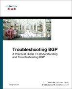
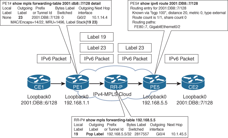
Figure 12-5 gives a brief overview of the 6PE routing and label distribution (control plane) across the MPLS cloud. In this topology, the egress PE router PE5 allocates a BGP label 23 for the destination CE2 prefix 2001:DB8::7/128 and advertises it to its IPv6 peer PE1 with the next-hop value of PE5 loopback address. Because the core is MPLS enabled, the PE router then advertises an implicit-null label toward the P/RR router RR-P, which is the penultimate-hop for PE5. The RR-P router allocates a label value of 19 and advertises toward the PE1 router. Both the PE1 and PE5 routers are having EBGP peering with the CE routers, respectively. The PE1 routers advertise the CE2 loopback address as an EBGP prefix toward the CE1 router.

After the control-plane information is exchanged, the traffic can start from CE1 toward CE2. When an IPv6 packet sent from router CE1 toward CE2 reaches PE1, the PE1 performs a lookup in its IPv6 routing table and finds the prefix with the outgoing label of 23 and the next-hop of PE5 loopback. Then the PE1 router performs a label forwarding information base (LFIB) lookup for the PE5 loopback and finds a label of 19 learned from the RR-P router. The PE1 router adds the BGP label 23 on top of the IPv6 packet received from CE1 and then adds the IGP label 19 on top of the BGP label and forwards the packet toward the RR-P router. This makes the IPv6 packet transparent inside the service provider core network. The RR-P router then receives the MPLS packet with a label value of 19, performs a LFIB lookup, and finds that it is the penultimate-hop for PE5. It then strips off the IGP label and forwards the packet with just the BGP label 23. When the packet is received by PE5, it performs a lookup in its BGP table and finds the next-hop to reach 2001:DB8::7/128 is 2001:DB8:0:57::7. PE5 then performs the forwarding information base (FIB) lookup and forwards the traffic of the outgoing interface toward CE2.
Figure 12-6 depicts the data forwarding in the 6PE deployment.
6PE Configuration
6PE is configured by following these simple steps:
Step 1. Configure IGP. IS-IS or OSPF is enabled in the service provider core to provide PE to PE reachability. The PE loopbacks should be advertised with the IGP as a /32 prefix.
Step 2. Configure MPLS. Enable MPLS on all the core network interfaces. After enabling MPLS, there should be an LSP between all the PE routers in the network.
Step 3. Configure MP-IBGP peering between PEs. Establish IPv6 peering between the PE routers. 6PE uses the MP-IBGP session to distribute IPv6 routes over the MPLS IPv4 network. When establishing an MP-IBGP session between the PE routers, ensure that the session is IPv6 MPLS label capable.
Step 4. Configure IPv6 routing between PE and CE. Use IPv6 static, IPv6 enabled dynamic routing, or IPv6 EBGP peering between the PE and the CE routers. Note that there is no VRF configured in case of 6PE. The PE-CE interfaces are part of the global IPv6 unicast routing table.
For configuration and verification of 6PE deployment, examine the same topology as shown in Figure 12-1. Example 12-12 displays the configuration of PE1, PE2, and PE3. PE1 is running IOS, PE2 is running IOS XR, and PE3 is running NX-OS. Notice that on IOS XR and NX-OS, the peering is established under address-family ipv6 labeled-unicast. This is because IOS XR and NX-OS do not support the send-label command, and it is using the peering under the labeled-unicast address-family BGP advertises labels to its peers. The address-family ipv6 labeled-unicast takes care of advertising the label to the peers. A 6PE router running IOS XR or NX-OS allocates a label for a prefix based on the allocate-label [all | policy] and sends an IPv6 labeled-unicast update to another 6PE router. The policy on IOS XR is defined using route policy and on NX-OS using route-maps.
Example 12-12 6PE Configuration
PE1 - IOS
ipv6 unicast-routing
ipv6 cef
!
interface Loopback0
ip address 192.168.1.1 255.255.255.255
ip ospf 100 area 0
!
interface GigabitEthernet0/1
description Connected to CE1
no ip address
ipv6 address FE80::1 link-local
ipv6 address 2001:DB8:0:16::1/64
!
interface GigabitEthernet0/2
description Connected to RR-P
ip address 10.1.14.1 255.255.255.0
ip ospf 100 area 0
mpls ip
!
router ospf 100
router-id 192.168.1.1
!
router bgp 100
bgp router-id 192.168.1.1
bgp log-neighbor-changes
no bgp default ipv4-unicast
neighbor 2001:DB8:0:16::6 remote-as 200
neighbor 192.168.5.5 remote-as 100
neighbor 192.168.5.5 update-source Loopback0
!
address-family ipv6
neighbor 2001:DB8:0:16::6 activate
neighbor 192.168.5.5 activate
neighbor 192.168.5.5 send-community both
neighbor 192.168.5.5 send-label
exit-address-family
!
mpls ldp router-id Loopback0 force
PE2 - IOS XR
interface Loopback0
ipv4 address 192.168.2.2 255.255.255.255
ipv6 address 2001:db8::2/128
!
interface GigabitEthernet0/0/0/0
ipv6 address fe80::2 link-local
ipv6 address 2001:db8:0:26::2/64
!
interface GigabitEthernet0/0/0/1
ipv4 address 10.1.24.2 255.255.255.0
!
router ospf 100
router-id 192.168.2.2
area 0
interface Loopback0
!
interface GigabitEthernet0/0/0/1
!
!
!
router bgp 100
bgp router-id 192.168.2.2
address-family ipv6 unicast
allocate-label all
!
neighbor 192.168.5.5
remote-as 100
update-source Loopback0
address-family ipv6 labeled-unicast
!
!
neighbor 2001:db8:0:26::6
remote-as 200
address-family ipv6 unicast
route-policy pass in
route-policy pass out
!
!
!
route-policy pass
pass
end-policy
!
mpls ldp
router-id 192.168.2.2
interface GigabitEthernet0/0/0/1
PE3 - NX-OS
install feature-set mpls
feature-set mpls
feature mpls l3vpn
feature-set bgp
!
interface loopback0
ip address 192.168.3.3/32
!
interface Ethernet2/1
no switchport
ipv6 address 2001:db8:0:36::3/64
no shutdown
!
interface Ethernet2/2
no switchport
ip address 10.1.34.3/24
ip router ospf 100 area 0.0.0.0
mpls ip
no shutdown
!
mpls ldp configuration
router-id Lo0
!
router ospf 100
router-id 192.168.3.3
!
router bgp 100
router-id 192.168.3.3
address-family ipv6 unicast
allocate-label all
neighbor 2001:db8:0:36::6
remote-as 200
address-family ipv6 unicast
neighbor 192.168.5.5
remote-as 100
update-source loopback0
address-family ipv6 labeled-unicast
Note
If using a static route or dynamic IPv6 routing protocol, perform mutual redistribution between the IPv6 IGP and BGP IPv6 address-family.
6PE Verification and Troubleshooting
The first step to verify after configuring 6PE is to ensure that the 6PE have full mesh MP-IBGP peering, and they are exchanging the capability to advertise labels for IPv6 unicast. The established BGP sessions are verified using the command show bgp ipv6 unicast summary on Cisco IOS and the command show bgp ipv6 [unicast | labeled-unicast] summary on IOS XR and NX-OS.
Use the command show bgp ipv6 unicast neighbors neighbor-ip on Cisco IOS and the command show bgp ipv6 labeled-unicast neighbors neighbor-ip on IOS XR and NX-OS. Example 12-13 verifies that the 6PE routers are exchanging labeled-unicast capability to advertise labels to the peers. Notice that even though PE5 is an IOS router, on PE2 and PE3 labeled-unicast capability is being advertised and received.
Example 12-13 6PE MPLS Labels Advertising Capability
PE1 - IOS
PE1# show bgp ipv6 unicast neighbors 192.168.5.5
BGP neighbor is 192.168.5.5, remote AS 100, internal link
BGP version 4, remote router ID 0.0.0.0
BGP state = Idle
Neighbor sessions:
0 active, is not multisession capable (disabled)
Stateful switchover support enabled: NO
Do log neighbor state changes (via global configuration)
Default minimum time between advertisement runs is 0 seconds
For address family: IPv6 Unicast
BGP table version 19, neighbor version 1/19
Output queue size : 0
Index 0, Advertise bit 0
Community attribute sent to this neighbor
Sending Prefix & Label
Slow-peer detection is disabled
! Output omitted for brevity
PE2 - IOS XR
RP/0/0/CPU0:PE2# show bgp ipv6 labeled-unicast neighbors 192.168.5.5
BGP neighbor is 192.168.5.5
Remote AS 100, local AS 100, internal link
Remote router ID 192.168.5.5
BGP state = Established, up for 02:26:28
! Output omitted for brevity
Non-stop routing is enabled
Multi-protocol capability received
Neighbor capabilities:
Route refresh: advertised (old + new) and received (old + new)
Graceful Restart (GR Awareness): advertised
4-byte AS: advertised and received
Address family IPv6 Labeled-unicast: advertised and received
Received 170 messages, 0 notifications, 0 in queue
Sent 150 messages, 0 notifications, 0 in queue
Minimum time between advertisement runs is 0 secs
. . .
PE3 - NX-OS
PE3# show bgp ipv6 labeled-unicast neighbors 192.168.5.5
BGP neighbor is 192.168.5.5, remote AS 100, ibgp link, Peer index 1
BGP version 4, remote router ID 192.168.5.5
! Output omitted for brevity
Neighbor capabilities:
Dynamic capability: advertised (mp, refresh, gr)
Dynamic capability (old): advertised
Route refresh capability (new): advertised received
Route refresh capability (old): advertised received
4-Byte AS capability: advertised received
Address family IPv6 Unicast: received
Address family IPv6 Label Unicast: advertised received
Graceful Restart capability: advertised
. . .
After the capability has been confirmed, verify that the IPv6 BGP labels are being received on each of the 6PE routers. Example 12-14 illustrates the verification of the local BGP label allocation and received BGP labels information using the command show bgp ipv6 unicast labels. The In Label signifies the local allocated label and the Out Label signifies the label received from the remote peer. PE5 allocates label 23 for the prefix 2001:DB8::7/128, and this is verified on all the remote 6PE routers, and vice versa.
Example 12-14 Verifying IPv6 BGP Labels
IOS
PE1# show bgp ipv6 unicast labels
Network Next Hop In label/Out label
2001:DB8::6/128 2001:DB8:0:16::6
23/nolabel
2001:DB8::7/128 ::FFFF:192.168.5.5
nolabel/23
IOS XR
RP/0/0/CPU0:PE2# show bgp ipv6 unicast labels
! Output omitted for brevity
Network Next Hop Rcvd Label Local Label
*> 2001:db8::6/128 2001:db8:0:26::6
nolabel 24007
*>i2001:db8::7/128 192.168.5.5 23 nolabel
NX-OS
PE3# show bgp ipv6 unicast labels
! Output omitted for brevity
Network Next Hop In label/Out label
*>e2001:db8::6/128 2001:db8:0:36::6
27/nolabel (default)
*>i2001:db8::7/128 ::ffff:192.168.5.5
nolabel/23
IOS
PE5# show bgp ipv6 unicast labels
Network Next Hop In label/Out label
2001:DB8::6/128 ::FFFF:192.168.3.3
nolabel/27
::FFFF:192.168.1.1
nolabel/23
::FFFF:192.168.2.2
nolabel/24007
2001:DB8::7/128 2001:DB8:0:57::7
23/nolabel
Notice the next-hop for the remote prefixes on each 6PE router. Except on the IOS XR router, all the routers show the next-hop as the IPv4 mapped IPv6 address. But because the labels are exchanged between the 6PE routers, the reachability is present without even modifying the next-hop to a valid IPv4 address.
Even though the prefixes in the BGP table may show IPv4 mapped IPv6 address, the IPv6 RIB shows the next-hop as the peering loopback IP of the remote 6PE router. Based on the IPv4 next-hop, the packets are label switched in the core. This is verified based on the CEF table output. The command show ipv6 cef ipv6-address [detail] displays the IPv6 CEF entry, which shows the outgoing interface as well as the MPLS labels, which are used for forwarding the packets. Example 12-15 examines the output of the IPv6 routing table and the CEF table thereof. Notice that all three 6PE routers show the MPLS label value of 23, which they learned from the remote 6PE router PE5. The IGP label is the same on all three nodes because they all connect to the RR-P router, which allocated an IGP label of 19 for the 192.168.5.5/32 address.
Example 12-15 IPv6 Routing Table and CEF Entry on 6PE
IOS
PE1# show ipv6 route 2001:db8::7/128
Routing entry for 2001:DB8::7/128
Known via "bgp 100", distance 200, metric 0, type internal
Route count is 1/1, share count 0
Routing paths:
192.168.5.5%default indirectly connected
MPLS label: 23
Last updated 1d07h ago
PE1# show ipv6 cef 2001:db8::7/128 detail
2001:DB8::7/128, epoch 0, flags [rib defined all labels]
recursive via 192.168.5.5 label 23
nexthop 10.1.14.4 GigabitEthernet0/2 label 19
IOS XR
RP/0/0/CPU0:PE2# show route ipv6 2001:db8::7/128
Routing entry for 2001:db8::7/128
Known via "bgp 100", distance 200, metric 0
Tag 300, type internal
Installed Jan 31 04:50:36.358 for 1d10h
Routing Descriptor Blocks
::ffff:192.168.5.5, from ::ffff:192.168.5.5
Nexthop in Vrf: "default", Table: "default", IPv4 Unicast, Table Id:
0xe0000000
Route metric is 0
No advertising protos.
RP/0/0/CPU0:PE2# show cef ipv6 2001:db8::7/128 detail
! Output omitted for brevity
via ::ffff:192.168.5.5, 3 dependencies, recursive [flags 0x6000]
path-idx 0 NHID 0x0 [0xa1759050 0x0]
recursion-via-/128
next hop VRF - 'default', table - 0xe0000000
next hop ::ffff:192.168.5.5 via ::ffff:192.168.5.5:0
next hop 10.1.24.4/32 Gi0/0/0/1 labels imposed {19 23}
Load distribution: 0 (refcount 1)
Hash OK Interface Address
0 Y Unknown ::ffff:192.168.5.5:0
NX-OS
PE3# show ipv6 route 2001:db8::7/128 detail
2001:db8::7/128, ubest/mbest: 1/0
cand ubest/mbest: 1/0, ufdm in/update: 1/0
*via ::ffff:192.168.5.5%default:IPv4, [200/0], 1d07h, bgp-100, internal, tag
300 (mpls)
client-specific data: 1
recursive next hop: ::ffff:192.168.5.5/128
extended route information: BGP origin AS 300 BGP peer AS 300
MPLS[0]: Label=23 E=0 TTL=0 S=0
Use the command show mpls forwarding to view the IGP label and the IPv6 prefix label. Example 12-16 demonstrates the verification of the BGP label and the IGP label. The command also shows the information of the outgoing interface, which is the core facing interface.
Example 12-16 MPLS Forwarding Table Output
PE1# show mpls forwarding-table 2001:db8::7/128 detail
Local Outgoing Prefix Bytes Label Outgoing Next Hop
Label Label or Tunnel Id Switched interface
None 23 2001:DB8::7/128 0 Gi0/2 10.1.14.4
MAC/Encaps=14/22, MRU=1496, Label Stack{19 23}
FA163E8A3E23FA163EB62BA28847 0001300000017000
No output feature configured
PE1# show mpls forwarding-table 192.168.5.5
Local Outgoing Prefix Bytes Label Outgoing Next Hop
Label Label or Tunnel Id Switched interface
21 19 192.168.5.5/32 0 Gi0/2 10.1.14.4
The IPv6 addresses are only enabled on the service provider edge routers; the traceroute tool is used to verify the path for the IPv6 packet. The IPv4-only nodes in the path display the IPv4 mapped IPv6 address. Note that these addresses are used to represent the address of IPv4-only nodes as an IPv6 address.
Example 12-17 demonstrates the use of traceroute to trace the path for the IPv6 packet from CE2 to CE1. The first hop in the output is the PE router with IPv6 address. The next-hop is the RR-P router, which is an IPv4-only node and thus displays the IPv4 mapped IPv6 address.
CE2# traceroute
Protocol [ip]: ipv6
Target IPv6 address: 2001:db8::6
Source address: 2001:db8::7
Insert source routing header? [no]:
Numeric display? [no]:
Timeout in seconds [3]:
Probe count [3]:
Minimum Time to Live [1]:
Maximum Time to Live [30]:
Priority [0]:
Port Number [0]:
Type escape sequence to abort.
Tracing the route to 2001:DB8::6
1 2001:DB8:0:57::5 13 msec 3 msec 3 msec
2 ::FFFF:10.1.45.4 17 msec 18 msec
3 2001:DB8:0:16::1 [MPLS: Label 23 Exp 0] 5 msec 6 msec 7 msec
4 2001:DB8:0:16::6 13 msec 17 msec 13 msec
Note
If an IPv4-only node does not have IPv6 software at all, it cannot understand the IPv6 packet and hence cannot generate the ICMPv6 message. In that case, the P router drops the packet. This results in an output of ‘* * *’ in the traceroute for that P router.
IPv6 VPN Provider Edge (6VPE)
With the introduction of RFC 4659, MPLS VPNs are extended to IPv6 VPN. IPv6 VPN Provider Edge (6VPE) routers provide the capability of providing IPv6 VPN services to customers over an IPv4 MPLS infrastructure.
Each IPv6 VPN has its own separate address space and is maintained in a separate routing table using virtual routing and forwarding (VRF). The VPN routes are exchanged across different sites via a new VPN-IPv6 or VPNV6 address-family. The VPNv6 address-family peering has the capability code 1 (multiprotocol BGP), AFI=2 (for IPv6), and SAFI=128 (MPLS labeled VPN-IPv6).
Like IPv4 MPLS Layer 3 VPNs, a VPNv6 route is made unique by attaching a route-distinguisher (RD) value before the prefix. The labeled VPN-IPv6 MP_REACH_NLRI itself is encoded as specified in [MPLS-BGP]—RFC 3107, which defines how label information is carried in BGP. The prefix belongs to the VPN-IPv6 address-family, or a VPNv6 route is a 24-byte address consisting of 8 bytes for RD followed by an IPv6 address, which is 16 bytes.
Figure 12-7 shows the 6VPE deployment architecture. In this topology, the PE routers (6VPE) provide both IPv4 and IPv6 VPN services to the customers. The service provider core network still runs on IPv4-MPLS, which means the service providers do not need to upgrade their core infrastructure but only make changes to the edge routers.

6VPE routers perform the following functions:
![]() Participate in IPv4 IGP to establish internal reachability inside the MPLS cloud.
Participate in IPv4 IGP to establish internal reachability inside the MPLS cloud.
![]() Form LDP peering within the IPv4 core network for binding labels.
Form LDP peering within the IPv4 core network for binding labels.
![]() Run MP-BGP4 to advertise IPv6 reachability and distribute VPN-IPv6 labels among them. The labels can be distributed as follows:
Run MP-BGP4 to advertise IPv6 reachability and distribute VPN-IPv6 labels among them. The labels can be distributed as follows:
![]() Per-Prefix label: The 6VPE node distributes labels for each IPv6 prefix learned via the VRF interfaces.
Per-Prefix label: The 6VPE node distributes labels for each IPv6 prefix learned via the VRF interfaces.
![]() Per-CE label: The 6VPE node aggregates all the routes learned from one particular CE and advertises one label for them.
Per-CE label: The 6VPE node aggregates all the routes learned from one particular CE and advertises one label for them.
![]() Per-VRF label: The 6VPE node advertises one label for all the IPv6 prefixes learned via the VRF interfaces.
Per-VRF label: The 6VPE node advertises one label for all the IPv6 prefixes learned via the VRF interfaces.
Note
The MP-IBGP peering between the 6VPE devices can be either full meshed or all the 6VPEs can exchange the relevant information via peering with RR over the VPNv6 address-family.
IPv6-Aware VRF
A service provider can provide both IPv4 as well as IPv6 VPN services to a customer in a single VRF. The older method of configuring VRF on Cisco IOS using the command ip vrf vrf-name only allows for IPv4-only VPNs. To allow a VRF to support both IPv4 as well as IPv6 VPN, use the command vrf definition vrf-name. Both IOS XR and NX-OS support both IPv4, as well as IPv6 address families under the VRFs. Example 12-18 illustrates the configuration of IPv6-capable VRF on all three platforms.
Example 12-18 IPv6-Aware VRF Configuration
PE1 - IOS
vrf definition red
rd 100:1
!
address-family ipv4
route-target export 100:1
route-target import 100:1
exit-address-family
!
address-family ipv6
route-target export 100:1
route-target import 100:1
exit-address-family
PE2 - IOS XR
vrf red
address-family ipv4 unicast
import route-target
100:1
!
export route-target
100:1
!
address-family ipv6 unicast
import route-target
100:1
!
export route-target
100:1
PE3 - NX-OS
vrf context red
rd 100:1
address-family ipv4 unicast
route-target import 100:1
route-target export 100:1
address-family ipv6 unicast
route-target import 100:1
route-target export 100:1
Note
Cisco IOS provides a migration command for conversion of VPNv4 to multiprotocol VRF using the command vrf upgrade-cli multi-af-mode vrf vrf-name. This command forces migration from old CLI for IPv4-only capable VRF to new Multi-AF capable VRF CLI.
6VPE Next-Hop
The next important concept to understand is the BGP next-hop with IPv6-VPN. MP-BGP currently has the constraint that the BGP Next-Hop field in the MP_REACH_NLRI attribute needs to be of the same address-family as the NLRI encoded in the MP_REACH_NLRI attribute. In case of VPN-IPv6 NLRI advertisement, this means that the BGP Next-Hop field must belong to the VPN-IPv6 address-family.
Because 6VPE feature supports IPv6 VPN service over an IPv4 backbone, the BGP Next-Hop field may be encoded (when peering over IPv4-MPLS) with a VPN-IPv6 prefix; that is, a VPNv6 prefix.
![]() RD is set to zero.
RD is set to zero.
![]() The 16-byte IPv6 address is encoded as an IPv4-mapped IPv6 address, with the IPv4 address being the address of the advertising PE.
The 16-byte IPv6 address is encoded as an IPv4-mapped IPv6 address, with the IPv4 address being the address of the advertising PE.
IPv6 is also capable of peering over the IPv6 backbone. In such a case, the BGP next-hop is an RD followed with a plain IPv6 address.
The notation RD:IPv4-prefix, used for VPNv4 prefixes, could not be used for VPNv6 prefixes because it conflicts with the IPv6 prefix notation. For instance, 100:1:2001::/64 could be interpreted as an IPv6 prefix or as an VPNv6 prefix with a RD of 100:1. For that reason, VPNv6 prefixes use the notation [RD]ipv6-address. In this case, it would be [100:1]2001::/64.
Route Target
Each VRF is associated with Route Target (RT) import and export rules. Like IPv4 VPNs, 6VPE will also use the RT import and export rules in the following manner:
![]() Associated with each VRF is an export RT list. When a VPN route is exported into BGP and advertised to other PEs in MP-IBGP, all the RTs in the export RT list of the corresponding VRF are included in the BGP advertisement.
Associated with each VRF is an export RT list. When a VPN route is exported into BGP and advertised to other PEs in MP-IBGP, all the RTs in the export RT list of the corresponding VRF are included in the BGP advertisement.
![]() Associated with each VRF is an import RT list. This list defines the values that should be matched against to decide whether a route is eligible to be imported into that VRF. The import rule is that all routes tagged with at least one RT associated with a given VRF will be imported into that VRF. Ingress PE performs such filtering during route import.
Associated with each VRF is an import RT list. This list defines the values that should be matched against to decide whether a route is eligible to be imported into that VRF. The import rule is that all routes tagged with at least one RT associated with a given VRF will be imported into that VRF. Ingress PE performs such filtering during route import.
Unless it is a PE also acting as an RR, a PE router discards any VPNv6 route whose RT does not match any of the import RTs on any of the configured VRFs on the router. This behavior acts as an automatic inbound route filtering for both IPv4 as well as IPv6 VPNs.
When the policy of a PE router changes, such as a new VRF is added or a new import RT is added to an existing VRF, the PE router must acquire the routes it may previously have discarded. This is done using a BGP’s Route Refresh capability described in RFC 2918. Note that ROUTE-REFRESH messages defined in RFC 2918 have an AFI value of 2 and a SAFI value of 128 for requesting refresh for VPNv6 routes. The 6VPE automatically triggers a ROUTE-REFRESH request on relevant PE changes.
Note
A PE providing both IPv4 as well as IPv6 VPN services as part of same VRF allows for sharing the same as well as a distinct RT between IPv4 and an IPv6 address-family under VRF.
6VPE Control Plane
Examine the 6VPE Control-Plane flow as shown in Figure 12-8. CE1 is running IPv6 services. The PE routers PE1 and PE5 may provide both IPv4 as well as IPv6 VPN services. The core facing interfaces are IPv4 and MPLS enabled. IPv6 is not enabled in the MPLS core network. The 6VPE routers have a common peering with the RR router RR-P. The customer routers (CE1 and CE2) are part of IPv6 VRF routing table on the 6VPE and not the global IPv6 routing table as in the case of 6PE deployment.

Figure 12-8 shows the process for signaling the control plane as listed in the following steps:
Step 1. The 6VPE router learned a prefix 2001:DB8::7/128 from the CE2 router in the VRF. The 6VPE router PE5 then assigns a VPNv6 label for the prefix and advertises it toward the RR-P router, which is then replicated to the relevant 6VPE routers with valid import RT statements under the VRF.
Step 2. The egress 6VPE router PE5 assigns the next-hop value for the VPNv6 prefix. The Next-Hop field for the VPNv6 prefix is set to the egress PE IPv4 address, which is typically the VPNv6 peering loopback IP.
Step 3. In the IPv4-MPLS core, PE5 advertises an implicit-null or POP label (label value 3) toward the RR-P router. The RR-P router updates its LFIB table with this information and accordingly updates the FIB. The implicit-null label is added on top of the VPNv6 label for the prefix 2001:DB8::7/128.
Step 4. The RR-P router then allocates a label value of 19, which is then swapped with the POP label and propagated toward the Ingress PE router. If RR router does not lie in the data or forwarding path of the MPLS VPN traffic, then RR just reflects the information received from a PE router to other PE routers.
Step 5. On receiving an update from the RR router, the 6VPE router verifies which VRF has imported the advertised RT value of the egress 6VPE router. Based on the lookup, the VPNv6 prefix is then installed in the respective IPv6 VRF routing table and then downloaded to the FIB. Before installing the IPv6 prefix into the Cisco Express Forwarding (CEF) table, the 6VPE router resolves the next-hop label information for the next-hop value, which is in the ::ffff.[ip-address] format.
Step 6. After the next-hop is resolved, CEF will install a label stack for the learned prefix where the outer label will be LDP label (19) learned via RR-P router and the inner VPN label is the one learned from BGP (23). It is important to note that the CEF table being referenced here is the VRF CEF table and not the global CEF table.
6VPE Data Plane
Based on the signaled 6VPE control-plane information, the data plane functions and forwards the traffic across the MPLS core. Figure 12-9 explains the IPv6 packet forwarding from the CE1 to the CE2 router across the MPLS IPv4 core network.

The 6VPE data plane operations shown in Figure 12-8 are also explained in the following steps:
Step 1. Router PE1 receives an IPv6 packet from CE1 for the destination 2001:DB8::7/128.
Step 2. On receiving the packet, PE1 performs a lookup in the VRF CEF table, which results in label stack (two labels) imposition: the BGP label 23 and the IGP label 19. After the labels are imposed on the packet, the packet is forwarded to the upstream router RR-P.
Step 3. The RR-P router receives the labeled packet and performs an LFIB lookup on the top label, which is the IGP label. Because the next-hop is the PE router, it POPs the top label and forwards a single label packet (VPN label) to PE5.
Step 4. On PE5, the label lookup in ingress VRF CEF yields egress interface toward CE2. The VPN label is disposed of and just the IPv6 packet is forwarded to the CE2 router.
6VPE Configuration
To understand the 6VPE deployment, examine the same topology as shown in Figure 12-1. The PE routers are now acting as 6VPE routers and are running all the services that are run on a 6VPE node. Example 12-19 illustrates the 6VPE configuration on all three 6VPE routers running different OSs. The MPLS and IPv4 core configuration remains the same as Example 12-12. Notice that the VRF on Cisco IOS is being attached to an interface using the vrf forwarding vrf-name command rather than ip vrf forwarding vrf-name command. This new command is used when the vrf definition command is being used to configure Multi-AF VRF.
Example 12-19 6VPE Configuration
PE1 - IOS
interface GigabitEthernet0/1
vrf forwarding red
ipv6 address FE80::1 link-local
ipv6 address 2001:DB8:0:16::1/64
!
router bgp 100
bgp router-id 192.168.1.1
bgp log-neighbor-changes
no bgp default ipv4-unicast
neighbor 192.168.4.4 remote-as 100
neighbor 192.168.4.4 update-source Loopback0
!
address-family vpnv6
neighbor 192.168.4.4 activate
neighbor 192.168.4.4 send-community extended
neighbor 192.168.4.4 next-hop-self
exit-address-family
!
address-family ipv6 vrf red
neighbor 2001:DB8:0:16::6 remote-as 200
neighbor 2001:DB8:0:16::6 activate
exit-address-family
PE2 - IOS XR
interface GigabitEthernet0/0/0/0
vrf red
ipv6 address fe80::2 link-local
ipv6 address 2001:db8:0:26::2/64
!
router bgp 100
bgp router-id 192.168.2.2
address-family vpnv6 unicast
!
neighbor 192.168.4.4
remote-as 100
update-source Loopback0
address-family vpnv6 unicast
next-hop-self
!
!
vrf red
rd 100:1
address-family ipv6 unicast
!
neighbor 2001:db8:0:26::6
remote-as 200
address-family ipv6 unicast
route-policy pass in
route-policy pass out
PE3 - NX-OS
interface Ethernet2/1
no switchport
mac-address 0000.0101.002f
vrf member red
ipv6 address 2001:db8:0:36::3/64
!
router bgp 100
router-id 192.168.3.3
address-family ipv4 unicast
address-family vpnv6 unicast
neighbor 192.168.4.4
remote-as 100
update-source loopback0
address-family vpnv6 unicast
next-hop-self
vrf red
address-family ipv6 unicast
neighbor 2001:db8:0:36::6
remote-as 200
address-family ipv6 unicast
The route reflector router RR-P only reflects the VPN prefixes to the other PE routers.
6VPE Control-Plane Verification
The first step of control-plane verification in 6VPE begins on the egress 6VPE router, which locally learns the destination IPv6 prefix in a VRF. Use the command show ipv6 route vrf vrf-name ipv6-address to verify whether the route is present in the VRF routing table. Example 12-20 demonstrates the verification of the IPv6 route present in the VRF routing table. Note that both the source and the destination CE route are present in the VRF routing table. 2001:DB8::6/128 is learned from CE1, whereas the 2001:DB8::7/128 is locally learned from the CE2 router. There may be multiple paths from which the prefix might be learned, but by default, only the best routes get installed in the RIB.
Example 12-20 Verifying IPv6 Route in VRF Routing Table
PE5# show ipv6 route vrf red
! Output omitted for brevity
B 2001:DB8::6/128 [200/0]
via 192.168.1.1%default, indirectly connected
B 2001:DB8::7/128 [20/0]
via FE80::7, GigabitEthernet0/2
After the route is verified to be present in the VRF V6-RIB, verify the prefix in the BGP VPNv6 table as well. When verifying the prefix present in the VPN table, also verify the VPN-IPv6 label allocated by the 6VPE router. On Cisco IOS and NX-OS, use the command show bgp vpnv6 unicast vrf vrf-name ipv6-address or use show bgp vrf vrf-name vpnv6 unicast ipv6-address to verify the prefix and the label allocated by the 6VPE router. Both of these commands are not supported on IOS XR. Use the same command show bgp vpnv6 unicast vrf vrf-name ipv6-address to verify the prefix and the label information on IOS XR.
Examine the output as displayed in Example 12-21. In this example, the prefix 2001:DB8::7/128 is a locally learned VPN-IPv6 prefix. Notice the format of the prefix in the VPN-IPv6 table. Its in the format [RD]IPv6-Address. This is because the prefix is learned from an IPv6-enabled peer. The 6VPE router PE5 allocates a label value of 23 for the locally learned prefix.
Example 12-21 Verifying the CE Prefix in VPNv6 Table
PE5# show bgp vpnv6 unicast vrf red 2001:db8::7/128
BGP routing table entry for [100:5]2001:DB8::7/128, version 38
Paths: (1 available, best #1, table red)
Advertised to update-groups:
2
Refresh Epoch 1
300
2001:DB8:0:57::7 (FE80::7) (via vrf red) from 2001:DB8:0:57::7 (192.168.7.7)
Origin IGP, metric 0, localpref 100, valid, external, best
Extended Community: RT:100:1
mpls labels in/out 23/nolabel
rx pathid: 0, tx pathid: 0x0
The next step is to verify that there is VPNv6 neighborship from the 6VPE router toward the RR or the remote 6VPE router. If there is no RR in the network, a full mesh neighbor relationship between all the 6VPE routers is required. Use the command show bgp vpnv6 unicast all summary on Cisco IOS or use show bgp vpnv6 unicast summary on IOS XR and NX-OS platforms to verify the VPNv6 neighbor relationship.
After the peering is established, the 6VPE routers exchange the VPN prefixes and labels between each other. Example 12-22 displays the output of the same command as shown in Example 12-21 to verify the prefixes present in the remote 6VPE router. Notice that all three 6VPE routers have the same label 23 as the received label or out label. Because the RD on the advertising 6VPE router is 100:5, and on the receiving side it is 100:1, the prefix is viewed under two RDs on the receiving 6VPE routers.
Example 12-22 Verifying VPNv6 Prefix on Ingress 6VPE
PE1 - IOS
PE1# show bgp vpnv6 unicast vrf red 2001:db8::7/128
BGP routing table entry for [100:1]2001:DB8::7/128, version 7
Paths: (1 available, best #1, table red)
Advertised to update-groups:
1
Refresh Epoch 1
300, imported path from [100:5]2001:DB8::7/128 (global)
::FFFF:192.168.5.5 (metric 3) (via default) from 192.168.4.4 (192.168.4.4)
Origin IGP, metric 0, localpref 100, valid, internal, best
Extended Community: RT:100:1
Originator: 192.168.5.5, Cluster list: 192.168.4.4
mpls labels in/out nolabel/23
rx pathid: 0, tx pathid: 0x0
PE2 - IOS XR
RP/0/0/CPU0:PE2# show bgp vpnv6 unicast vrf red 2001:db8::7/128
BGP routing table entry for 2001:db8::7/128, Route Distinguisher: 100:1
Versions:
Process bRIB/RIB SendTblVer
Speaker 5 5
Last Modified: Feb 4 22:46:29.408 for 1d05h
Paths: (1 available, best #1)
Not advertised to any peer
Path #1: Received by speaker 0
Not advertised to any peer
300
192.168.5.5 (metric 3) from 192.168.4.4 (192.168.5.5)
Received Label 23
Origin IGP, metric 0, localpref 100, valid, internal, best, group-best,
import-candidate, imported
Received Path ID 0, Local Path ID 1, version 5
Extended community: RT:100:1
Originator: 192.168.5.5, Cluster list: 192.168.4.4
Source VRF: default, Source Route Distinguisher: 100:5
PE3 - NX-OS
PE3# show bgp vrf red vpnv6 unicast 2001:db8::7/128
BGP routing table information for VRF default, address family VPNv6 Unicast
Route Distinguisher: 100:1 (VRF red)
BGP routing table entry for 2001:db8::7/128, version 6
Paths: (1 available, best #1)
Flags: (0x08001a) on xmit-list, is in u6rib, is best u6rib route
vpn: version 8, (0x100002) on xmit-list
Advertised path-id 1, VPN AF advertised path-id 1
Path type: internal, path is valid, is best path
Imported from 100:5:2001:db8::7/128
AS-Path: 300 , path sourced external to AS
::ffff:192.168.5.5 (metric 42) from 192.168.4.4 (192.168.4.4)
Origin IGP, MED 0, localpref 100, weight 0
Received label 23
Extcommunity:
RT:100:1
Originator: 192.168.5.5 Cluster list: 192.168.4.4
VRF advertise information:
Path-id 1 advertised to peers:
2001:db8:0:36::6
VPN AF advertise information:
Path-id 1 not advertised to any peer
In most of the deployments, the role of RRs is not extended to PE and therefore does not have any VRFs configured. The VPNv6 prefixes can be verified on the RR using the RD values using the command show bgp vpnv6 unicast rd asn:nn ipv6-address.
The VPN labels are verified by using the command show bgp vpnv6 unicast vrf vrf-name labels or by using the command show mpls forwarding vrf vrf-name ipv6-address. The show mpls forwarding command is not available for verifying a specific prefix on IOS XR; thus the command show bgp vpnv6 unicast vrf vrf-name labels can be used. Example 12-23 displays both the locally allocated and remotely learned VPN labels.
Example 12-23 Verifying VPN Labels
IOS
PE1# show mpls forwarding-table vrf red 2001:db8::7/128
Local Outgoing Prefix Bytes Label Outgoing Next Hop
Label Label or Tunnel Id Switched interface
None 23 2001:DB8::7/128[V]
0 Gi0/2 10.1.14.4
PE1# show bgp vpnv6 unicast vrf red labels
Network Next Hop In label/Out label
Route Distinguisher: 100:1 (red)
2001:DB8::6/128 2001:DB8:0:16::6
23/nolabel
2001:DB8::7/128 ::FFFF:192.168.5.5
nolabel/23
IOS XR
RP/0/0/CPU0:PE2# show bgp vpnv6 unicast vrf red labels
! Output omitted for brevity
Status codes: s suppressed, d damped, h history, * valid, > best
i - internal, r RIB-failure, S stale, N Nexthop-discard
Origin codes: i - IGP, e - EGP, ? - incomplete
Network Next Hop Rcvd Label Local Label
Route Distinguisher: 100:1 (default for vrf red)
* i2001:db8::6/128 192.168.1.1 23 24008
*> 2001:db8:0:26::6
nolabel 24008
*>i2001:db8::7/128 192.168.5.5 23 nolabel
NX-OS
PE3# show bgp vpnv6 unicast labels
! Output omitted for brevity
Network Next Hop In label/Out label
Route Distinguisher: 100:1 (VRF red)
*>e2001:db8::6/128 2001:db8:0:36::6
28/nolabel (red)
*>i2001:db8::7/128 ::ffff:192.168.5.5
nolabel/23
Route Distinguisher: 100:5
*>i2001:db8::7/128 ::ffff:192.168.5.5
nolabel/23
Note
The control-plane verification of the MPLS core network is same as shown in the 6PE section.
6VPE Data Plane Verification
From the SP’s perspective, the 6VPE control-plane verification begins from the ingress 6VPE routers. In the topology shown in Figure 12-1, the ingress 6VPE routers are PE1, PE2, and PE3. After the routes are received from the remote 6VPE router PE5, the best route is installed in the RIB, which then gets installed in the FIB—that is, the CEF table or on platforms that support non-CEF–based hardware-based forwarding such as Nexus. The CEF table is downloaded into the hardware, which then programs the ASICs to perform the packet forwarding.
When a packet comes from the CE1 router destined toward 2001:DB8::7/128, the 6PE router looks at the CEF table for the information. The CEF table contains the information on the outgoing interface and the label stack information. Examine the CEF table on the 6VPE routers as shown in Example 12-24. Notice that in this output, 23 is the VPNv6 label received from PE5, and label 19 is the IGP label received from router RR-P. Recall that the router RR-P allocated a local label of 19 for the destination 192.168.5.5/32.
PE1# show ipv6 cef vrf red 2001:db8::7/128 detail
2001:DB8::7/128, epoch 0, flags [rib defined all labels]
recursive via 192.168.5.5 label 23
nexthop 10.1.14.4 GigabitEthernet0/2 label 19
Because the IOS XR platform maintains the CEF table on the ingress as well as the egress line cards, the CEF table is verified both on the RP as well as the ingress and egress line cards on the router. Use the command show cef vrf vrf-name ipv6 ipv6-address hardware [ingress | egress] [detail] [location location-id], where the ingress or egress option is specified when the hardware entry is looked up on the ingress or the egress line card. The location option is useful when the command needs to be verified on a particular line card. If not specified, the command is executed on the active route processor on the router. Example 12-25 demonstrates the verification of hardware forwarding and CEF information on the IOS XR 6VPE router. Notice that in the hardware CEF entry output, the next-hop VRF is seen as the default. The table id 0xe0000000 represents the global (default) routing table.
Example 12-25 6VPE Forwarding Information on IOS XR
RP/0/0/CPU0:PE2# show cef vrf red ipv6 2001:db8::7/128
2001:db8::7/128, version 7, internal 0x5000001 0x0 (ptr 0xa140c5f4) [1],
0x0 (0x0), 0x208 (0xa14db230)
Updated Feb 4 22:46:29.731
Prefix Len 128, traffic index 0, precedence n/a, priority 3
via ::ffff:192.168.5.5, 3 dependencies, recursive [flags 0x6000]
path-idx 0 NHID 0x0 [0xa176b0bc 0x0]
recursion-via-/128
next hop VRF - 'default', table - 0xe0000000
next hop ::ffff:192.168.5.5 via ::ffff:192.168.5.5:0
next hop 10.1.24.4/32 Gi0/0/0/1 labels imposed {19 23}
! Verify the Ingress Hardware Programming
RP/0/0/CPU0:PE2# show cef vrf red ipv6 2001:db8::7/128 hard ing det loc 0/0/CPU0
Sat Feb 6 14:32:56.241 UTC
2001:db8::7/128, version 7, internal 0x5000001 0x0 (ptr 0xa140c5f4) [1],
0x0 (0x0), 0x208 (0xa14db230)
Updated Feb 4 22:46:29.730
Prefix Len 128, traffic index 0, precedence n/a, priority 3
gateway array (0xa12a05a0) reference count 1, flags 0x4038, source rib (7),
0 backups
[1 type 1 flags 0x48089 (0xa14f5398) ext 0x0 (0x0)]
LW-LDI[type=0, refc=0, ptr=0x0, sh-ldi=0x0]
gateway array update type-time 1 Feb 4 22:46:29.730
LDI Update time Feb 4 22:46:29.730
via ::ffff:192.168.5.5, 3 dependencies, recursive [flags 0x6000]
path-idx 0 NHID 0x0 [0xa176b0bc 0x0]
recursion-via-/128
next hop VRF - 'default', table - 0xe0000000
next hop ::ffff:192.168.5.5 via ::ffff:192.168.5.5:0
next hop 10.1.24.4/32 Gi0/0/0/1 labels imposed {19 23}
Ingress platform showdata is not available.
Load distribution: 0 (refcount 1)
Hash OK Interface Address
0 Y Unknown ::ffff:192.168.5.5:0
! Verify the Egress Hardware Programming
RP/0/0/CPU0:PE2# show cef vrf red ipv6 2001:db8::7/128 hard egr det loc 0/0/CPU0
2001:db8::7/128, version 7, internal 0x5000001 0x0 (ptr 0xa140c5f4) [1],
0x0 (0x0), 0x208 (0xa14db230)
Updated Feb 4 22:46:29.730
Prefix Len 128, traffic index 0, precedence n/a, priority 3
gateway array (0xa12a05a0) reference count 1, flags 0x4038, source rib (7),
0 backups
[1 type 1 flags 0x48089 (0xa14f5398) ext 0x0 (0x0)]
LW-LDI[type=0, refc=0, ptr=0x0, sh-ldi=0x0]
gateway array update type-time 1 Feb 4 22:46:29.730
LDI Update time Feb 4 22:46:29.730
via ::ffff:192.168.5.5, 3 dependencies, recursive [flags 0x6000]
path-idx 0 NHID 0x0 [0xa176b0bc 0x0]
recursion-via-/128
next hop VRF - 'default', table - 0xe0000000
next hop ::ffff:192.168.5.5 via ::ffff:192.168.5.5:0
next hop 10.1.24.4/32 Gi0/0/0/1 labels imposed {19 23}
Egress platform showdata is not available.
Load distribution: 0 (refcount 1)
Hash OK Interface Address
0 Y Unknown ::ffff:192.168.5.5:0
The traffic forwarding counters are verified using the show mpls forwarding command by looking at the Packets Switched or Bytes Switched counters, although it is hard to say that the interface is switching the correct packets or not, because in real deployments, there could be multiple VRFs that are routing across the same outgoing interface toward the core. Use the command show mpls forwarding labels label-value hardware [ingress | egress] [location location-id] to view the hardware forwarding counters on an IOS XR router.
Another method to verify the traffic forwarding counters is by using the command show interface interface-name accounting. This command displays the various protocols that are running on an interface and their respective input and output counters. Multiple iterations of the command should be collected while investigating traffic-forwarding issues on IOS XR.
Example 12-26 illustrates the use of the show interface accounting command to verify the forwarding counters. Notice the MPLS counters on the interface before and after the ping test is performed. Because five pings were successful, the input and output packets were increase by 5 each (5 for echo sent on output counters and 5 for echo-reply received on input counters). The counters are incrementing for MPLS because the VPNv6 traffic in the core is viewable only as MPLS traffic and not as regular IPv4 or IPv6 unicast traffic.
Example 12-26 Verifying Interface Accounting Statistics
RP/0/0/CPU0:PE2# show interface gigabitethernet0/0/0/1 accounting
GigabitEthernet0/0/0/1
Protocol Pkts In Chars In Pkts Out Chars Out
IPV4_UNICAST 261333 20337753 46929 2305821
IPV6_UNICAST 21017 2062274 20995 1964348
MPLS 10 1180 14426 968553
ARP 84 5040 84 3528
IPV6_ND 13296 1193736 10306 742016
RP/0/0/CPU0:PE2# ping vrf red 2001:db8::7
Type escape sequence to abort.
Sending 5, 100-byte ICMP Echos to 2001:db8::7, timeout is 2 seconds:
!!!!!
Success rate is 100 percent (5/5), round-trip min/avg/max = 9/15/19 ms
RP/0/0/CPU0:PE2# show interface gigabitethernet0/0/0/1 accounting
GigabitEthernet0/0/0/1
Protocol Pkts In Chars In Pkts Out Chars Out
IPV4_UNICAST 261334 20337829 46929 2305821
IPV6_UNICAST 21017 2062274 20995 1964348
MPLS 15 1770 14431 969163
ARP 84 5040 84 3528
IPV6_ND 13296 1193736 10306 742016
On NX-OS there are no CEF-related commands. The forwarding information on NX-OS is verified by using the command show forwarding [vrf vrf-name] ipv6 route v6-route. This command displays the next-hop value, outgoing interface, and MPLS labels (if any). Based on the MPLS labels, the forwarding information is further verified using the command show mpls switching ip-address. This command helps attain the local as well as the outgoing label for the MPLS packet.
Verify the hardware forwarding information for the VPNv6 prefix using the command show system internal forwarding vrf vrf-name ipv6 route v6-address [module number] [detail]. This command provides details about the hardware adjacency index and the egress interface. Both the values are in hex-format. Using the value received from the preceding command, verify the details of the hardware adjacency using the command show system internal forwarding adjacency adj-value [module number] [detail]. This command displays the egress interface information, which should match with the logical interface (LIF) value observed before. It also displays the packet forwarding count, which can be further used to troubleshoot any hardware-forwarding issues in 6VPE setup.
Example 12-27 demonstrates the 6VPE hardware forwarding verification on the NX-OS platform.
Example 12-27 6VPE Forwarding Verification on NX-OS
PE3# show forwarding vrf red ipv6 route 2001:db8::7
slot 2
=======
IPv6 routes for table red/base
*2001:db8::7/128
10.1.34.4 Ethernet2/2 PUSH2 19 23
! Verify MPLS Forwarding Information
PE3# show mpls switching 192.168.5.5
Legend:
(P)=Protected, (F)=FRR active, (*)=more labels in stack.
In-Label Out-Label FEC name Out-Interface Next-Hop
21 19 192.168.5.5/32 Eth2/2 10.1.34.4
! Verify hardware forwarding information for the VPNv6 prefix
! Fetch the Adjacency Index and Egress Interface from this command
PE3# show system internal forwarding vrf red ipv6 route 2001:db8::7 module 2
Hardware IPv6 FIB entries for table red/base
2001:db8::7/128, Index: 0x1406
Dev: 1 Adj Index: 0xa020, Lif Base: 0, Egress Lif: 0x4003
! Using the adjacency information from above command, verify the hardware
! programming for the VPNv6 prefix. The below command displays the IGP and
! the VPN label received from remote peer
PE3# show system internal forwarding mpls adjacency 0xa020 module 2 detail
Device: 1 Index: 0xa020 dmac: 0022.5576.1283 smac: 0026.980c.8bc1
PUSH TWO Label0 19 Label1 23
e-vpn: 1 egr_lif: 0x4003 packets: 0 bytes: 0
DI: 0x1 CCC: 4 L2_FWD: NO FRR_TE: 0 FRR_NODE_ID: 0x0
! Use the below command to verify the adjacency information and also the
! packet forwarding counters
PE3# show system internal forwarding adjacency entry 0xa020 module 2 detail
Device: 1 Index: 0xa020 DMAC: 84a0.c009.a603 SMAC: 00f0.4000.4400
LIF: 0x4003 (Ethernet2/2) DI: 0x1 ccc: 4 L2_FWD: NO RDT: YES
packets: 650 bytes: 81900 zone enforce: 1
! Verify Hardware forwarding information for the MPLS Label
! Label 21 is the locally assigned label for the the loopback of PE5
PE3# show system internal forwarding mpls label 21 detail
slot 2
=======
Table id = 0x1
------------------
----+--------+------------+----------+----------+-----------+-------- +
Dev | Index | In-label | AdjIndex | LIF | Out-label | Op
----+--------+------------+----------+----------+-----------+-------- +
Device: 0 HW Index: 0x1655 In Label: 21 Valid: 1
Vpn valid: 1 M: 0 Eos: 0 Lif or Label1: 0 Vpn or Table id: 1
Adj Index: 0xa01d Egr Lif: 0x4003
Out Label: 19 SWAP ONE
! Use the below command to verify the MPLS hardware adjacency information and
! the MPLS packet forwarding counters
PE3# show system internal forwarding adjacency entry 0xa01d module 2 detail
Device: 1 Index: 0xa01d DMAC: 84a0.c009.a603 SMAC: 00f0.4000.4400
LIF: 0x4003 (Ethernet2/2) DI: 0x1 ccc: 4 L2_FWD: NO RDT: YES
packets: 650 bytes: 81900 zone enforce: 1
Summary
This chapter covered various IPv6 BGP concepts and features that are important for understanding and troubleshooting IPv6 BGP deployments in both enterprise and service provider environments. It explained how the IPv6 BGP next-hop value is calculated. The chapter discussed how IPv6 routes can be exchanged over IPv4 transport and how IPv4 routes can be exchanged over IPv6 transport and next-hop. With both the methods, the next-hop calculation method is different. The chapter then explored 6PE and 6VPE deployments and various commands to configure, verify, and troubleshoot these deployments.
References
RFC 2545, BGP-4 Multiprotocol Extensions for IPv6 IDR, P. Marques, F. Dupont, IETF, https://tools.ietf.org/html/rfc2545, March 1999.
RFC 5549, Advertising IPv4 Network Layer Reachability Information with an IPv6 next Hop, F. Le Faucheur, E. Rosen. IETF, http://tools.ietf.org/html/rfc5549, May 2009.
RFC 4798, Connecting IPv6 Islands over IPv4 MPLS Using IPv6 Provider Edge Router (6PE), J. De Cleroq, D. Ooms, S. Prevost, F. Le Faucheur, IETF, https://tools.ietf.org/html/rfc4798, February 2007.
RFC 4659, BGP-MPLS IP Virtual Private Network (VPN) Extension for IPv6 VPN, J. De Cleroq, D. Ooms, M. Carugi, F. Le Faucheur, IETF, https://tools.ietf.org/html/rfc4659, September 2006.
RFC 4760, Multiprotocol Extensions for BGP-4, Y. Rekhter, T. Bates, R. Chandra, D. Katz, IETF, https://tools.ietf.org/html/rfc4760, January 2007.
RFC 3107, Carrying Label Information in BGP-4, Y. Rekhter, E. Rosen, IETF, https://tools.ietf.org/html/rfc3107, May 2001.
Cisco. IPv6 VPN over MPLS: 6PE and 6VPE—Configuration Guide, http://www.cisco.com,
Cisco. Implementing IPv6 over MPLS—6PE, http://www.cisco.com.