12
Electrical distribution
Introduction
In the past and indeed up to quite recently, film studios often generated their own power. This was in the form of a d.c. voltage, usually at 120 V and mainly used because of the need to supply carbon arc sources used in the film industry. The basis of the 120 V was the importation from America of the lighting technology used in film studios. As the public supply authorities did not in general, supply d.c. voltage, it was necessary for the film studio to install large diesel driven generators. Associated with the 120 V systems used was the need to have much larger copper feeder cables than would be normal in the UK, due to the current being used. With the advent of much more sophisticated d.c. power supplies, particularly of a size such as the film industry would demand, it was easier to supply systems with a.c. voltage and transform and rectify it to the 120V needed.
Nearly all TV and film premises these days use a.c. power supplies provided by the local electricity authority. In the smaller installation one three-phase transformer will usually be fed from an 11 kV high-voltage main. In the larger installations, it is quite possible that a high voltage ring main will be used with several sub-stations to transform from 11 kV to 415 V within the building and positioned adjacent to the areas of maximum demand. A big problem for supply authorities these days is the fact that the supply system itself contains a high proportion of harmonics and this has been created by the use of discharge lighting systems such as fluo-rescents and, in many cases, solid state semi-conductor equipment such as computer power supplies. Unfortunately in large premises using lighting systems, we do have a high proportion of fluorescent lighting in the offices, we may have a high proportion of discharge lighting on the sets and we certainly have many dimmer racks full of solid state equipment generating harmonics. In theory, in a balanced three-phase system all the current will flow in the phase conductors and not in the neutral. Unfortunately in the situations quoted, it is possible to have as much current in the neutral as contained in the phases themselves.
So far we have discussed the supply of power for use from the public supply system, but of course it is possible to have a back-up generator used within the premises to prevent any problems if the public power supply fails. If back-up power systems are used only for technical equipment then the loads may not be too great and small diesel generators are a good proposition. When applied to the lighting systems where considerable amounts of power are required, it is not always economically viable to install standby power equipment. Most TV companies install a small generator, sufficiently large to keep a small amount of crucial equipment operating and capable of being used for transmission; with sufficient power spare to enable say, captions and one announcer to be lit.
In very large installations, it is more than likely that two incoming supplies from the local 11 kV distribution system are provided to the premises and obviously there has to be an arrangement made to have changeover facilities in the event of failure. It is extremely advantageous in a large building to use a ring main for the high voltage supplies so that in the event of damage or faults on any equipment, an alternative supply route can be utilised. In premises such as a large TV studio complex, there is a need to keep the studios working as much as possible, therefore when maintenance is required, it is important that the local transformer can be bypassed and the area supplied from another area so that essential maintenance is carried out. Routine maintenance will obviously have to be carried out on all the switchgear on a regular basis.
Within any installation, the siting of the main transformers and switchgear either connected with high voltage or low voltage systems has to be carefully considered and the installation carefully planned. In the smaller installation, only one low voltage sub-station will probably be provided, additionally one switch room will be installed close to the incoming supply and within this room will be a factory built assembly from specialist manufacturers which will incorporate the circuit breakers, fuses, mcbs and metering systems. A very important point in the selection of the electrical power systems is the fact that the electrical designer concerned should ensure that most equipment is fairly standard, therefore any problems can be quickly overcome and the spares holding is reasonable in size. Usually the lighting power is controlled by a special switch on the lighting console, probably remotely engaging a large contactor in the switch room. Although it would be nice to think that this contactor would be operated as a ‘no load’ device, thus ensuring that the contacts within the switchgear are not burnt by opening under large electrical loads and thus causing arcing, there is no guarantee that this will not happen. In practice therefore the switchgear has to interrupt large currents.
In general, it's not a good idea to install systems that would automatically shut off the supply in the event of an overload. Systems are generally designed to have warnings displayed for overloads so that the operating staff can take avoiding action. The installed capacity of lumi-naires can quite often exceed that of the power allowed for any installation, therefore generally the discipline of the operators is required to ensure there is no overload of the system.
For ease of operation and to ensure the minimum disruption in the event of any faults, generally with lighting installations, it is wise to have several small pieces of switchgear feeding dimmer racks, thus ensuring no one item of equipment on failing would take the whole system out of action. One good thing about most modern dimming equipment, is that it is generally well protected by fuses or mcbs and therefore faults are contained within individual parts of the system and not reflected back.
In film and TV studios, lighting creates the greatest single demand for electricity. With demands ranging from hundreds of kilowatts to possibly even thousands of kilowatts, lighting generally has to be considered almost separately from the rest of the installation. The loads it can impose on a three-phase system can have quite severe effects on the rest of that system.
Most installations in the UK use BS 4343 plugs and sockets in either 16 A, 32 A or 63 A rating. One great advantage of using this range for plugs and sockets is that they are very readily available from many sources and are relatively cheap. In practice, they have proved to be extremely rugged and very adaptable. One problem to be considered when using BS 4343 connectors in a grid system, is that they will not pass through the grid slots which could change the way in which the electrical distribution is routed.
There are no hard and fast rules with regard to the provision of lighting power outlets in any installation. The numbers involved will require liaison for the individual installation between the lighting consultant and the user of the premises. The factors however to be taken into account include maximum usage of any premises so that on installation all needs are catered for because it's so much easier and cheaper to do it in the first place than modify systems at a later date.
Film studios are a slightly different case when compared with TV, because their power intakes do not generally feed dimming systems. So the main requirement is to have banks of switchgear with individual contactors or isolators supplying large distribution frames somewhere within the studio. These are usually at floor level although there could be some power distribution at high level if a grid is installed or a gallery is provided around the studio itself. Film power distribution tends to be rather flexible in nature using long leads to distribute power to various parts of the sets involved. These days, the requirements of British Standards for power distribution, be it on outside broadcasts or filming, involve the use of specified distribution units so that an installation is somewhat safer than the old style of production. These distribution units contain circuit breakers, fuses and at times RCDs to prevent any harmful electric shock. Other types of power connectors are also allowed for under British Standards for the distribution of power on film and TV, but generally it is preferable to use the BS 4343 range because of ease of replacement.
A frequent problem that often emerges with installations is the possibility of induced electromagnetic interference, either on the vision or sound systems in TV studios, and the possibility of hum on audio in other installations. The most important factor to avoid hum loops is to use a star point connection for the earth conductors within the installation, i.e. all earth conductors within an area should be taken to a common terminal. From our experience, it is very easy to blame the dimmer system for problems, whereas the electrical installation within the building is often the root cause. As an example, in a studio in Milan, northern Italy, there were severe three-phase hum bars on the vision system and a high degree of hum on the audio. Upon investigation, it was found that due to the dryness of the soil in the area, causing poor conductivity in the earth spikes, the electrical contractor had laid a continuous conductor around the building, which was approximately 300 m long, with several earth rods spaced at 20 m intervals. The various parts of the installation, such as the electrical, vision and sound, were all connected in a rather haphazard way to the loop around the building. Between the earth conductor and neutral there was about 37 V of hum on a system used for 220 V mains. The supplier of the dimmers, a world famous English based lighting company, were accused of problems with their thyristor dimmers. One of the authors travelled to Milan with a representative of the lighting company and, having assessed the situation, persuaded the customer to disconnect the ring either side of one of the earth points and to take one earth from the central apparatus area down to this point. Immediately, the three-phase interference on the vision disappeared and the audio became satisfactory. Although the solution was relatively easy, the cost of getting the installation up to a good technical standard was reasonably high, which proves that some consultation, when building or planning installations, is extremely valuable and avoids unwanted costs at a later date.
12.1 Sub-station and switchgear
When using powers of hundreds of kilowatts, it obviously makes sense to have large transformers very close to the areas concerned. This enables high voltage feeds, say 11 kV, to be fed to local sub-stations and then be transformed down to a 415 V three-phase system. One snag with having the transformer very close to the dimmer room is that the impedance of the cables between the dimmer cabinets and the transformer is extremely low and allows very high fault currents to occur. This means that the dimming equipment supplied will have to meet exacting tests.
In the smaller installation, it will obviously not be practical to allow the lighting system to be fed from its own transformer and it will have to share power requirements with the remainder of the building. In larger installations however, it is preferable that the lighting system has its own transformer and when systems are of the order of 500 kW this makes life so much easier. It may also be possible in the very large installation that two studios can share a transformer and even bigger transformers can be installed. It can be advantageous to have a dimmer room with two sets of switchgear, fed by a common transformer, covering two studios.
Lighting loads in a studio; when the console is being used in anger, on some types of shows, might vary from the solo spotlight on a performer perhaps at 2 kW, to a complete lighting change on the other hand of 300–400 kW of power and this imposes enormous surges on the power system. Thus, the inherent stability of the lighting power system has to be good and this requirement is met by high quality transformers on one hand and modern self stabilising dimming systems on the other.
If we take the distribution in a large dimmer room the main incoming power from the adjacent transformer will be fed through armoured cables to the switchgear and then via a busbar system through the switchgear. The switchgear provides for an isolator per dimmer rack. This is for (a) safe isolation for maintenance and (b) to isolate parts of the equipment in the event of a major fault. It is important to have individual isolators for the equipment and not a common isolator to more than one piece of equipment which could cause a problem during the normal operation of the premises; and of course it is not very useful when you have to shut down the entire system just to maintain one dimmer. All of the lighting power will usually be under the control of a contactor on the input to the switchboard, so that lighting power can be remotely switched from the lighting control room. This contactor will have be quite large: it will also have to be rated for live working conditions. There is no guarantee that ‘no load’ conditions will exist at the time the contactor operates.
It is usual to feed from the isolators on the switchgear to the dimmer racks with armoured multi-core cable and as this has a definite bending radius, it is often advantageous to use parallel multi-core cables of a slightly smaller physical size so that they may be manipulated easily within the dimmer room. Generally dimmer racks are fed via the top of the units which makes access fairly easy although on some occasions we are likely to find the air conditioning installation technicians trying to impose their trunking in the most awkward places. Other than armoured cables, the use of trunking to enclose PVC power feeder cables can be advantageous, due to the fact that PVC cables are much easier to manipulate then their armoured counterparts. It has already been mentioned in Chapter 8 that it is extremely important to provide sufficient space for the termination of the mains input cables. The racks’ incoming cables may range from 16 mm2cables on smaller installations up to 400 mm2 cables or the equivalent on very large dimmer racks.
12.2 Power and balance for three phases
In the past, due to the British regulations pertaining at the time, which treated single and three-phase working voltages differently, it was very difficult to feed the lighting system effectively from three-phase supplies, owing to the need for defined limits of separation between socket outlets on different phases. In practice, this often meant that all floor sockets were on the same phase as the technical equipment. In trunking arrangements with socket outlets fitted and especially on barrels, it was difficult to prevent clusters of equipment appearing on the same phase causing large imbalances over the three phases. The main reason was that studios had to have the individual barrel outlets on the same phase; thus one third of the barrels would be connected to the ‘red’ phase, one third to ‘yellow’ and the remainder ‘blue’. Generally, the barrels were interspersed as sets of three for phase distribution. Thus barrel 1 would be red; barrel 2 blue, barrel 3 yellow and so on. Sometimes to get around loading problems in an installation, yellow and red phases would be used for lighting and blue for the remainder of the installation. Due to a change of IEE specification, which defines any voltage up to that of 1000V a.c. between conductors, or 600 V a.c. between conductors and earth, as low voltage, we are now covered for both 230 V and 400 V in one voltage range and the requirement for separation has lapsed. We can now quite happily design the lighting distribution to be spread over three phases for the ease of balancing the power system. Although it's possible to design the studio to work on three phases, and for that matter to arrange some form of uniform distribution throughout the grid system and lighting sockets generally, we have no guarantee that the luminaires will be plugged in a balanced way or that the use of the lights controlled by the lighting console will not, by coincidence, only use those on one phase only, by some chance of fate.
When the lighting director is producing his lighting plot for the electricians to use in the studio to plug the luminaires into the electrical supply system, he will have to bear in mind the phase of the various lighting power socket outlets in the area concerned so hopefully he can ensure a reasonable balance over three phases. If systems are using any form of ‘patch’ it may be that the LD indicates the lighting positions that he requires and allows the electricians to plug these into appropriate sockets. With a soft patch system in use it may be that the LD upon being given the dimmer numbers, can programme his console to suit the channel numbers in use. The main point that the LD will have to watch is the maximum capacity of each phase.
How is the lighting apportioned over the three phases so that one phase is not highly loaded in comparison to the others? It may be that the maximum current allowed on a phase dictates the amount of luminaires that the LD may use at any one time. Thus it is not always a simple matter for the LD to ask for various combinations of lighting equipment without having some regard for the supply concerned. For example, if the maximum current allowed is 200 A per phase, it will not be possible to allocate more than ten 5kW luminaires to that phase. If there were some guarantee that diversity was applied, i.e. all the dimmers were never to be higher than say 8 then more luminaires could be allocated per phase due to the lower individual current consumption.
These days where many installations do not have permanent LDs but most are brought in on contract, it's more than likely that any LD doesn't have an intimate knowledge of the premises concerned. It is extremely important therefore, that any technical literature that may be given to any guest LD in any premises, is extremely accurate and reflects faithfully the lighting electrical system together with details of the lighting console installation and any quirks within the installation with regard to the general power supplies. In practice, it's no good calling for six 10 kW luminaires to be used when the system does not even have any 10kW dimmers or, for that matter, sockets supplied.
12.3 Distribution systems
Probably the best place to start in our distribution system is to look at an individual circuit and see the initial effects of lighting power in a practical way and then how it affects the rest of the system. The current carrying capacity of a 4 mm2 PVC cable is 30 A and a 240 V 5kW circuit will draw 20.83 A, therefore superficially it would appear that this cable would be sufficient for our purposes; but unfortunately that's not the end of the story. It is important in any installation that the volts dropped by the current flowing down the cables does not exceed certain limits. The concern with voltage drop is that items of equipment might cease to operate correctly and therefore constitute some form of danger. In UK regulations, the maximum stipulated voltage drop is 4% of the nominal voltage, which is 9.6 V with a 240 V supply.
Obviously with the majority of lighting equipment, we are not so much concerned with the volt drop to the luminaire as the tungsten lamps will operate on any voltage from zero to their maximum. Our problem, in practice, if we lose too many volts down the cable is that the lamps will commence to burn at a lower colour temperature than that desired even at maximum applied volts, and although not critical in a theatre, this might prove to be a problem with aligning cameras. Voltage drop on a domestic installation will not be very high as the length of cables involved are relatively short. However, let's take a practical example in an installation using a 240 V 5 kW dimmer, feeding a socket in the acting area and the cable from the dimmer to the socket is 80 m long.
PVC single-core cable (in trunking) |
Voltage drop for 80 m (V) |
|
4 mm2 |
11 mV/A/m run |
18.3 |
6 mm2 |
7.3mV/A/m |
12.2 |
10 mm2 |
4.4mV/A/m |
7.3 |
It will be readily appreciated that the first two voltage drops exceed the limit as laid down by the present regulations, and only the 10 mm2 cable would be acceptable.
A further problem now arises. Most luminaires are fed via flexible cables and if we assume this to be a 4 mm2 three-cored flexible cable, then even a short lead, 5 m long, will give us 1.3 V of voltage drop on a 5kW luminaire. This has to be added to the 10 mm2 figure.
An even bigger problem occurs when the 80 m of 10 mm2 cable is terminated at grid level, instead of going directly to a socket in the acting area. This is usually to allow the interconnection of a 4mm2 flexible cable from the termination point, via a flip-flop cable system, down to a socket on a suspension bar. If this cable was 15 m long, we would get a further voltage drop of 4 V. If we run all the figures together, which might be quite possible in a TV studio installation, we therefore have, using 10 mm2 cable, a loss of 7.3 V. We have a further loss of 4 V on the feeder from the grid system to the bar outlet socket and the luminaire lead will also have a loss amounting to 1.3 V, so our total loss is 12.6 V, which is above the desired IEE technical parameters. However, in the studio, this might not give a problem with the intensity of light, but we do have to bear in mind that if this was a 240 V system, we would have a colour temperature change of 5K/V. When calculated this gives 12.6 × 5K = 63 K. It is not unknown in practice, unfortunately, that lamps are delivered from manufacturers with low operating colour temperatures and these may be around 3100 K for a nominal 3200 K lamp. So instead of our system now producing a start point of 3200 K, it may be we are closer to 3000 K, and of course we intended lining the TV cameras up around this point. If we reduce the dimmer to 7 which would be our normal starting point for technical line up, we would have a colour temperature output from the lamp of about 2850 K, which is really at the lower acceptable limit of the video camera and thus does not allow for any further dimming of the light sources if we are to maintain the cameras colour integrity.
Thus it is extremely important that cables between the areas and on the equipment themselves are as generous as possible to avoid voltage drop. It is, of course, possible to have the input transformers feeding the switchgear and dimmer racks adjusted so that they deliver high volts on input, say 250 V, to offset some of the voltage drop in a system, but this is a practice which should not be encouraged. By starting with high volts, which would be presented to the dimming system, and by suddenly getting a voltage surge, it might be that we rapidly exceed safe limits on the dimmers and this would be quite disastrous.
In most installations these days, electrical services will be generally conveyed by trunking or cable trays. Due to the amount of cables used in installations which may be pairs of single conductors or multi-core cables, it requires that the trunking and tray systems installed will have to be prefabricated from steel, due to its strength and rigidity. Cables fed by either system at high level in the premises will unfortunately be in the area of the highest temperatures. It may be that the use of cable trays is more advantageous with the cables being exposed to the air, particularly if not bunched, and probably not having the same electrical requirements of those that are totally enclosed. However, due to the need to keep the EM interference as low as possible, it is preferable to keep all cables from dimming systems in trunking rather than on trays and this is particularly important when the dimmers are feeding low level sockets within the premises where they may be in close proximity to sound circuits. As a guide, if separations of approximately 300 mm or greater are used between the lighting power cables, and any other installed cables, there generally will not be a problem. Another major advantage of metal trunking systems is that it can provide an extremely good earth continuity throughout the installation and in addition affords a high degree of mechanical protection to the cables. In the theatre, the trunking systems will be provided generally to the periphery of the stage area so that power feeds can be taken across to the lighting bars on flexible cables. In film studios, as already noted, most of the distribution will be at floor level. In TV studios however, nearly all the distribution is at high level and this means that the system has to be carefully integrated with the layout of any monopole bar, motorised pantograph or even a fairly simple lighting system such as fixed barrels. If we require clearance above a grid for access, it is important that trunking is not put in the most awkward places, thus creating possible hazards to the operational staff working in the area. Most systems will use trunking at high level, dropping it down to outlet points on a fairly regular basis and usually this will be a central box feeding four winch units at the same time. In the case of monopoles, quite complex socket arrangements are provided.
One problem with using dimmer systems is that the harmonic content of the waveforms is extremely high when they are in 90° conduction, and if we are not careful, we will have high circulating currents in the neutral and earth conductors.
Two basic rules are extremely important.
- All circuits wired from the dimmer room to the acting area should be wired as live/neutral pairs of conductors in the same conductor size. The use of several small independent phase conductors with a large common neutral is to be deprecated, because this in itself can cause a problem. For example, in one large broadcasting studio that was converted from saturable reactors to thyristor dimmers using common neutral systems, the circulating harmonics caused severe eddy currents in the trunking in the studio and created conditions where it was extremely difficult to hold a conversation against the noise, other than the fact the trunking was getting rather hot. It's worth noting that it cost quite a lot of money to correct this design error.
- Equally important, and at times capable of causing more problems, is the correct earthing of the system.
It is essential that the earthing system does not form a ring conductor within the system but all earths should be radial conductors, and if possible, taken to a nominated star point. To avoid problems on most installations these days, it is usual practice to adopt a ‘clean earth’ policy where the technical equipment is on a separate earth system to the dimming system – if this is at all possible. Any circulating earth currents can cause a greater problem with the sound and vision equipment than the electromagnetic interference radiated by the cables from the dimmers.
In addition to the power cables for the individual circuits from dimmer racks, there is a need for the control system inputs from the control room to all dimmer racks and these will be conveyed in either separate trunking or by small flexible cables fed within the racks themselves. On the whole the control cable is relatively immune from interference problems. The main precaution to take with analogue signal cables is to ensure that the cables are well screened internally. With digital inputs becoming more normal these days, control system interference is virtually non existent, as any random signals can be prevented from causing problems by checking all the data for error signals.
Other than the power wiring in the studio, there will be a need for additional trunking which provides for the control cables to and from the various control consoles within the studio and these would be as follows:
- Local electricians’ panel.
- Lighting hoist control panel.
- Scenery winch control panel.
These may be placed anywhere at studio floor level for the ease of the local operators, but in general they will tend to be grouped, particularly those for the electricians’ panel and the lighting hoist panel.
12.4 Distribution problems
The following example actually occurred in a small TV studio, where the windows over-looked a waterfront which was used as backing to the camera shots.
The air conditioning was not functioning as effectively as it should have been, the movement of air in the studio was not enough and the ceiling area was accumulating a pocket of very hot air. This was mainly caused by the use of several 5kW tungsten sources, fitted with IL Blue correction filters to counterbalance the daylight, rather than using IL Orange on the windows to correct to 3200 K or using discharge sources of a quarter the power for the same light level. There were also some 2 kW circuits in use for effects lighting.
The studio had originally been wired with flexible cables from the dimmer room, mounted on cable trays. However, it was felt that the cables could be tidier and the tray was replaced by PVC cables in trunking. It was then discovered that the trunking and cables were running at around 80°C.
In normal circumstances, the cables installed from the dimmer room to the studio may possibly have sufficed, if all the circuits were not selected simultaneously, thus avoiding a grouping problem. However due to the need to light the studio to a high level, all the luminaires had to be used and thus no diversity took place.
Taking into account the ambient temperature, together with the grouping factor of the cables in the trunking, it was essential to increase the cable size for the 5 kW circuits, which also had the advantage of reducing the voltage drop to the studio where even 5 V lost represents around 5% light loss in the studio.
There were two solutions to the cable heating problem – assuming no other changes.
1 Leave the existing trunking and cable for 2 kW circuits only and remove the 5 kW feed cables. Install new 100 × 100 mm trunking for the 5kW circuits with the cable size increased to a minimum of 10mm2.
2 Remove all the existing trunking and cable and rewire in rubber flexible (85°C) cable on perforated trays. No more than a double layer with a minimum of 6 mm2 for the 5 kW circuits and 4 mm2 for the 2 kW circuits.
Note: The use of tray allows a smaller cable size for the 5 kW circuits.
The second course of action was adopted as the solution to the problem. As can be appreciated, this merely reverted the situation to ‘Square One’.
12.5 Distribution sockets
With a limited number of dimmers, it is possible to have a power patch system so that the sockets to be powered in the ‘active lit’ area can be connected to dimmers as appropriate to the area concerned. This is often done in smaller installations where perhaps 24 dimmers are provided feeding 48 sockets. A good thing about patch systems is the fact that, usually, the power from the dimmer to the socket is on a ‘one to one’ basis with very little chance of circuit overloads occurring. If however, the dimmer units are provided with parallel sockets on the front panels for convenience, there is the danger of overloads if the operators are not careful.
Due to the flexible nature of monopole grids, it is necessary to provide a reasonable number of dimmers which cater for the maximum size of production in the studio but, because of the need to keep continually repositioning monopoles and to prevent long flexible leads, several parallel sockets at high level are required. Either we have a very clever switching system to prevent any of the individual circuits being overloaded or we rely upon the operators making the right decision when plugging up the various luminaire feeder cables.
In pantograph systems, when permanent catenary systems are employed feeding the individual luminaires on the base of the pantographs it is very seldom to find circuit overloads. This is because the system is strictly ‘one to one’.
Motorised barrel systems will employ a variety of sockets mounted adjacent to the suspension barrel for the luminaires. In general, the circuits will be 5kW and the minimum number usually supplied per 2.5 m bar, for example, will be three circuits. It is possible that one of these circuits or more, may be installed with parallel sockets across the dimmer circuit so that two small luminaires can be patched to one dimmer from the bar itself. In addition to the normal outlets for the Fresnels and softlights used, there will be a requirement for either additional standard sockets or for special sockets for cyclorama lighting units.
The distribution system will also feed floor outlets but the circuits are generally connected directly to the dimmer units. On occasions, it may be advantageous to switch between floor lighting power sockets and high level lighting power sockets, but if this is switched in the correct manner the power can only be in one place at any one time, therefore a circuit overload is avoided.
In a TV studio, other than the need for the power sockets for the normal lighting on any of the types of suspension used, there is a need for additional sockets to be used for effects lighting, cyc lighting and discharge lighting which may require connection to a three-phase system, and this is usually provided by special sockets in selected locations to suit the installation.
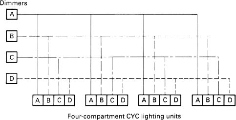
Figure 12.1 Cyclorama lighting distribution
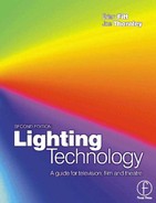
One area where special sockets are required is for the lighting of cyclorama cloths (Figure 12.1). Groundrow cyclorama units invariably are supplied with 625 W lamps per compartment. If we use 4-compartment groundrow units for 4-colour mixing, we can feed a string of eight of the same colour compartments from one dimmer, i.e. 8 x 625 W = 5kW (Figure 12.2(a)).
Special cables are supplied by manufacturers to allow the linking of several groundrow units. These may be integral to the unit itself or supplied as separate pre-formed cables in eight, four and single connector configurations. The cyc end of these cables are usually fitted with 9-pin connectors to mate with the cyc units; the other end is split into four standard studio plugs for circuits A, B, C and D (Figure 12.2(b) and (c)).
Cyclorama lighting units when employed at the top of cycs invariably use 1250 W lamps and we could therefore light four of the same compartments from one dimmer, i.e. 4 x 1250 W = 5kW (Figure 12.3). Top cyc units can be supplied by manufacturers with input cables to suit the installation power sockets. They can vary from a single cable and plug attached to each compartment to a 9-pin male connector, used for the four circuits, going to special sockets provided in the grid system.

Figure 12.2 Cyclorama electrical distribution
Figure 12.3 Permanently installed cyclorama distribution
As an example, let's take the case of overhead cyc lighting with four units used, each with four compartments fed from four 5 kW dimmers.
Dimmer A feeding the first colour, Dimmer B the second colour, Dimmer C the third colour and finally Dimmer D the fourth colour. In the case of groundrow units, obviously the four dimmers are still required but we now can feed eight sets of four compartment units rather than the four used at high level. For convenience, we can install sockets in groups of four representing A, B, C, D, for use by either cyclorama system. It may be that the barrel system at high level also has a permanent cyclorama lighting installation which would utilise groups of 9-pin ‘A, B, C, D,’ sockets where the sockets would be paralleled in groups of four, where each group, i.e. 4 x A, is fed from one dimmer output; 4 x B from another dimmer, etc. As an alternative, the 9-pin cyc sockets can be fed by four flexible cables, the ends of which are fitted with standard plugs, allowing them to be patched to any standard studio socket.
In addition to this type of socket used in the studio, there will be a need for distribution, in some studios, of 10 kW sockets when higher powered luminaires may be required. When the 10 kW socket is not being used, it is preferential to supply two 5kW sockets in parallel, switched from and adjoining the 10 kW socket and all fed from the same 10 kW dimmer, thus upon selection, one 10 kW socket could be used or two parallel 5 kW sockets. These 5 kW sockets would have to be subfused on the adjacent panel next to the selection switch.
12.6 Fuses and circuit breakers
There are two functions required from the protective devices we use, one of which will protect for normal overload conditions, such as lamps failing or incorrectly plugged luminaires creating too much current on a circuit. In addition, the devices have to be adequately rated so that they safely stand fault currents caused by short circuits.
The wiring going from the switchgear to the dimmer racks has to be protected by either fuses or some form of circuit breaker. Before we go any further it would perhaps be wise to look at the magnitude of currents that flow from the main switchgear to the dimmer racks. In a fairly straightforward simple installation using packs of 6 × 2.5 kW dimmers each pack, which would probably be connected to 240V single phase, would consume 62.5A on full load. At the other end of the scale, using a high density dimmer rack containing 192 5kW dimmers, spread over three phases, we would have 1333 A per phase on full load. With smaller systems it is probably just as easy to protect the input to the dimmer racks by fuses. However, with higher current systems, it is more than likely that the electrical installation engineer will install circuit breakers of sufficient rating to meet the demands of the dimmer racks. As far as the output of the individual dimmers themselves goes these can be protected by either mcbs or fuses.
At this point it would be worthwhile looking at fault currents. What do we mean by fault current?
If we are stupid enough to place a piece of wire across a 240 V supply and switch on, the wire disappears rather quickly. By using a simple bit of Ohm's law it will soon be realised that the current is governed by the resistance of the piece of wire and if the piece of wire does not have much resistance the current can become quite large. For example, if a piece of wire with a resistance of 0.01 f is placed across a 240 V supply, the current flowing through the piece of wire would be 24000 A. In practice we wouldn't just be concerned with a piece of wire across the 240 V supply, because in addition to the resistance of the wire will be the resistance of all the cables feeding to the initial point where the wire is inserted in the circuit. Thus, the nearer we are to the point of supply the greater will be the fault current. On the input to the main switchgear from the sub-station and its transformer we can get very high fault currents indeed. If, however, the fault occurs at the end of a 100 m of cable run the fault current will be relatively low. Although in practice it would be rare to have a short circuit at the output of a dimmer for example, the rules and regulations regarding protection state that we have to protect for a short circuit at this point. Thus the prospective fault current has to be verified for this point. Why should we be worried about a short circuit in the wiring system? We are concerned with avoiding short circuits in our lighting feeders because of the danger due to the magnetic and thermal effects it can produce in the conductors and on busbar systems. We must therefore place protective devices in the conductors which must operate sufficiently quickly and in absolute safety to prevent this kind of danger. If we are going to use a fuse, we can meet the fault current requirement by selecting fuses with a high rupturing capacity, for example BS 88 in the United Kingdom allows for a rupturing capacity of 80 kA. Another method of protecting circuits is by using an air circuit breaker (acb) or a moulded case circuit breaker (mccb). These will also have to be rated to meet the prospective fault current.
Thus the switchgear feeding the dimmer racks will be provided with, say, fuses to handle 400 A running current and if a normal overload occurs will rupture relatively quickly. In addition, they will have to fuse immediately with a fault current of around 20 000 A. Acbs and mccbs are often specified for high current applications of about 400 A and greater on switchgear. Fuses are generally used below this point.
Many mcbs that are used for circuits with much lower current capacity have fault current ratings of somewhere between 6000 A and 9000 A particularly in the type that we would select for dimmers. It is more than likely that the potential fault current of the circuits involved will exceed these values. It would seem at this point that an mcb could not be used to protect our outgoing circuits, however, in practice this is not the case, because we are allowed to use a device which is not quite adequate if we back it up with a fuse which adequately protects the complete circuit. Thus, if the prospective fault current was 8000 A and the breaking capacity of the mcb we had selected was 6000 A, we would have to back up the mcb with a fuse with a breaking capacity in excess of 8000 A so that the circuit was fully protected.
Most of the devices to protect the installation will have to be carefully selected. We have to bear in mind that there will be more than one device protecting the circuits so the protection devices have to be carefully integrated with each other so that discrimination is achieved. For example, it's no good having the mccb feeding the dimmer rack failing when only one outgoing dimmer circuit has a fault.
12.7 Meters
It's fairly obvious that the fault conditions can be calculated and appropriate measures be incorporated in the switchgear, dimmer racks and any ancillary equipment feeding a stage or studio area. Overload conditions are catered for by the selection of devices that disconnect the supply when a certain current level is reached.
From an operational point of view it is important that we monitor the parameters of the supply so that we do not create overloads on the main power intake. It may be that if you are on a special tariff, going ‘over the top’ costs real money. By putting voltmeters across the phases it will be possible to see the state of the voltage within the premises, although in general these are somewhat of a luxury because even if the volts are wrong you can do little or nothing about it. One of the problems with supplying voltmeters is: ‘where do you actually take the reading?’ If it's taken at the switchgear, it's quite possible that the voltage will be reasonable, if we took it at a studio socket it's more than likely it would be several volts lower and due to the varying lengths of run in a studio, it would be highly impractical to adopt a policy of looking at socket voltage outputs. Therefore the best voltage guide is probably the one provided by the switch-gear but, due to the various volt drops within the studio, this can be rather misleading in practice.
What can be done however, is to ensure that the capacity of the system is not exceeded by trying to draw too much current. If ammeters are supplied which monitor the current of the total system, and individually monitor supply to various parts of the system, then we can ensure an overload does not take place. On any lighting system it is preferable that an ammeter is placed in the incoming supply to the dimmer rack installation so that the total current can be monitored. This can then be displayed on remote metering systems in control rooms and in the dimmer room and at stage or studio floor level. The ammeters are also necessary for the operators to see the current in each phase so that the lighting load can be balanced across all three phases to avoid heavy neutral currents and the financial penalties imposed by supply companies for ‘out of balance’ loads. Modern metering systems use low volt signals to convey the information from special transducers built into the equipment. The metering systems should be placed for the operators’ benefit as it is essential that the operators can read clearly what is indicated. It is very frustrating to have a meter with a red segment indicating the overload area, when you actually can't see the needle and where it's pointing. Generally, if meters are supplied they will require little lights to illuminate the panels. Of course, self illuminating meters could be used and in recent years some use of gas discharge bar graphs have been used where rising columns of bars indicate the voltage and current levels reached. On the whole, analogue meters are preferable, although there's much to be said for a digital display where the current level is clearly displayed in figures and not open to the operators’ interpretation.
It's not a good idea to have a trip system which, on sensing an overload, would shut down that phase to avoid any further problems, because from an operational point of view this would be highly undesirable. Warning systems have been incorporated into metering systems in the past which, for instance, give some indication of either approaching the danger point or the actual overload condition per phase, but unfortunately the buzzers themselves can become a nuisance in practice and they have never been brought into general use.
It is essential to ensure there is no leakage of any currents down to earth, they should always come back up the correct paths. To ensure this, it is preferable that the earth leakage currents are monitored at the input to each dimmer rack and this can be achieved by having a current transformer mounted at the input of any rack where the input cables are taken through and then terminated. This ensures that the current flowing into the rack should equal the current flowing back up the return conductors and thus cancel out. Any imbalance would indicate a current flowing elsewhere and hence a fault condition. Earth leakage can be monitored in each rack and then, if a fault occurs a local indicator is activated. All the individual rack EL warning systems can be fed to a central unit which in turn sends a master warning signal to all interested parties. Isolating the problem is simply achieved by going to the dimmer room and seeing which individual rack has the fault.
12.8 Distribution on the ‘set’
In addition to the suspended production lighting, there will be a need for luminaires mounted on floor stands around the sets, together with small luminaires on special clamps attached to the top of scenery flats for local lighting in the sets. There will also be a requirement to have ‘practical’ lights. These will be similar to those found in any normal house or business premises and consist of table lamps, fluorescent fittings, wall mounted units and pendant fittings hanging from a ceiling. The use of these fittings is to give a realistic effect to the scene. However, the general lighting effect will not be provided by the practical lamps but by the main lighting being used cleverly by the LD to supplement the effect of say, a 100 W bulb.
We have to be careful with this 100W practical lamp, because it will no doubt be fed by relatively small electrical flex so that it looks right as far as the viewer is concerned, but unfortunately in practice the circuit may not have the correct back-up protection if anything goes wrong. It has already been noted in the section on dimming that it is very important to select the correct fuse for the circuit involved. If we take the standard studio or stage set-up, the 240V dimmers will be fused at about 10A or 20A, or possibly even more on some occasions. The problem that occurs when the practical is plugged into a lighting power outlet is that the cable size has reduced considerably with the use of flex for the practical and we must insert a subsidiary fuse at this point where the cable sizes change. If the practical is supplied from a wall outlet and the flex has to progress several metres across the acting area this also constitutes a source of danger. Our best bet is to ensure that we get as near to the practical as possible with well rated cable and then introduce an additional fuse at this point so that only a short piece of flex is used. The best method is to use special extension leads, but whereas the normal lead will just have a socket at the end of it, the special leads for practicals will have fuses fitted adjacent to the final socket.
Obviously for convenience when two practicals have to be used together in a room, the extension cables should be supplied with parallel sockets, each one of these fitted with a small local fuse. Thus, the 20 A fuse used with a 240 V 5 kW dimmer, will protect the cable all the way down to the sub distribution outlet. This can then be sub-fused at 5 A to supply the final piece of flex and the subsequent 100 W lamp.
Other than practical lamps, it is quite possible that some of the lights used on the scenery flats are also low wattage sources. These luminaires may be supplied from within the premises or are hired pieces of equipment, but in most cases they will be supplied with small mains leads fitted. Once again, we have to ensure that they are only plugged into a circuit that is correctly protected by a subsidiary fuse rather than directly plugged into the main lighting circuits.
With set dressing lights, which are often supplied from overhead sockets, it may be more convenient to have an adaptor unit with a plug that goes into a bar outlet, is sub-fused at that point and provides a smaller connector on its output. As an example; a 32 A BS 4343 plug may be used to go into the 32 A socket on the bar but the outlet from the adaptor unit would be a 16 A BS 4343 socket supplied via a fuse fitted in the adaptor.
Having said that we need to protect the circuits by the choice of the correct fuses, we must also ensure any cables feeding either set or practical lights are routed in such a manner that they are protected from mechanical damage at all times. This will require special covers over cables at floor level together with a careful choice of route through the scenery labyrinth.
On occasions, there may be a need to use an isolating transformer to give a higher degree of protection to some of the circuits appearing at floor level. Generally these will be those circuits used for musical instruments and of course, these will not be dimmed circuits. However, it is important to ensure that at any time any load such as a transformer, or motor, when plugged into the system is going to work correctly with the dimmers installed in that system. Some hired-in equipment may not be the same voltage as the supply system in the premises and it would be somewhat disastrous to put a 120 V hired-in device across the output of a 240 V dimmer.
The main lessons to be learnt are that:
(a) Check every point of detail at any time with regard to the disposition of small pieces of lighting equipment within sets.
(b) Check particularly on their ability to handle current and that they are suitable for the system voltage.
Finally, it's no good having protected a 100 W lamp with a small fuse to have the cable draped across a corner of the set in such a way that the first person going that way trips over and breaks a leg!