3
Theory of light
3.1 Electromagnetic spectrum
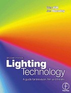
The narrow band of electromagnetic radiation which lies between UV and infrared with wavelengths from 0.0004 mm (400 nm) to 0.0007 mm (700 nm) is detectable by the human eye and is known as light (see Figure 3.1).
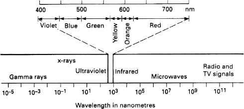
Figure 3.1 Electromagnetic spectrum
When an object is heated it radiates energy in the form of electromagnetic waves. These waves go from the radio wave end of the electromagnetic spectrum through the infrared, the visible, the UV, X-ray and gamma ray. Ultraviolet is invisible to human beings, but unfortunately, in significant amounts is extremely harmful. Infrared is also invisible and produces a sensation of heat, but fortunately with no adverse side effects. For most of the hot objects that we encounter on the planet earth the energy lies mainly in the infrared region. A cooker hot plate may show no visible signs of heat, but when a hand is held over it, it feels warm; we are experiencing infrared at about 500 K. When the hot plate is turned up and reaches 1000 K we see a slight glow coming from the element which is the onset of visible radiation. The plate also becomes noticeably hotter, showing that there is an increase in the amount of radiated energy. A good example of infrared radiation is that from the black luminaires that are used in the entertainment industry. There is no visible sign of heat from the body of the luminaire, although we get a nasty burn if we touch it.
The tungsten filament lamps radiate a white light around 3000 K. To produce UV radiation in significant amounts, temperatures of 3500 K and higher are required and most solid objects on earth melt by the time they reach this temperature. We generally produce temperatures around the 6000 K mark by mercury vapour lamps, such as fluorescents, xenons and HMI lamps and they all emit large amounts of UV radiation. When using discharge light sources, we have to be very much aware of the dangers connected with this type of illumination.
UV radiation
Description |
Wavelength |
UV – A |
315–380 nm |
UV – B |
280–315nm |
UV – C |
100–280 nm |
Ultraviolet radiation covers the range 4–400 nm and it begins at the short wavelength limit of visibility (violet) and extends to X-rays. It is divided into near (400–300 nm), far (300–200nm) and extreme (below 200 nm). The near UV energy is known generally as blacklight and often is used to excite fluorescent pigments used in dyes, paints and materials to produce effects for advertising and more importantly to us, in the theatre and sometimes on TV. The UV radiation in sunlight on the surface of the earth extends from about 320 nm to 390 nm and is generally our source of getting a suntan, with very long exposures causing cancer of the skin. Radiation between 300nm and 390nm is little absorbed by our bodies and therefore is not so active on human cells. Below 300 nm, UV becomes exceedingly dangerous to the human being. The radiation between 300 nm and 200 nm is well absorbed by the body, produces damage to cells and the effect is nearly always permanent. This is the reason we have to be so careful with discharge sources such as HMI and MSR.
For the purposes of this book, we are mainly concerned with the visible part of the spectrum and to a large extent the infrared. The visible gives us the light by which we can illuminate for the purposes of entertainment, the infrared gives us problems with heating and subsequently ventilation, which will be discussed later in the book.
3.2 F-number (f-stop)
The ‘f-number’ is the measurement of the theoretical amount of light that can pass through a lens. It is also colloquially known as the ‘stop’. To obtain the f-number of a lens, the focal length is divided by the diameter of the aperture. Thus, a 50-mm lens which has an aperture 25 mm wide, will be an f2 lens. The following are typical f-stops found on lenses: f1, f1.4, f2, f2.8, f4, f5.6, f8, f11, f16, f22, f32.
Each of the above divisions is ‘one stop’. The reciprocal of the square of the f-number, it gives the amount of light passing through the lens i.e. 1/stop2.
Note: The transmissions given are for perfect lenses and do not include optical loss.
3.3 The eye
A major problem with the human eye is that it can be fooled; it is not an absolute measuring instrument such as a colour meter, but relies mainly on comparative measurements to assess information (see Figure 3.2). If we show a human being, in a darkened room, a succession of similarly coloured lights with intervals of darkness between, the subject is totally unaware of a change over quite a wide range, e.g. from pale blue to a mid blue. However, two colours when shown side by side have only to vary by a small amount and the difference is noticeable. As we can process much visual information using our superior intelligence, the human eye does not have to be as good as that of many birds and animals.

Figure 3.2 The figure has many possible triangles although no triangles have been drawn. The V shaped figures can be ‘closed’ by your brain to form one large triangle, or ‘closed’ opposite the apex to form three. The eye can use the portion of the V triangle ‘undermeath’ the large white one to close off three smaller white triangles with an apex in each circle. You can also see a six pointed star by combining the large white triangle and the one formed by the Vs. These illusory triangles are called Kanizsa triangles after Professor Gaetano Kanizsa of the University of Trieste who first introduced them (Kanizsa, 1976)
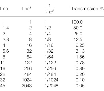
Figure 3.3 Photopic curve
When light enters the lens of the eye, it is received by the retina which consists of millions of photoreceptors, packed into an area about 1.5 cm2. Human beings have two types of receptors called ‘rods’ and ‘cones’, because we live in two distinct worlds – night and day. The cones which number approximately 7 million, are for the detailed full colour examination of objects in bright light; the rods, which number approximately 130 million, are for the examination of objects in low light conditions. Rods and cones are not dissimilar in their individual sensitivity; but to achieve a higher sensitivity several rods are coupled together, and this accounts for the eyes’ loss of sharpness at night. Due to the cones’ lower sensitivity, we all feel better doing fine work in high light levels when the cones are working efficiently.
The most important aspect of the eye is photopic vision which is used at normal levels of illumination. Not every individual has the same sensitivity, therefore the Commission International de l'Eclairage (CIE) adopted an internationally agreed response, which is called the CIE standard observer. This gives the standard sensitivity for the eye for wavelengths from 380 nm to 760 nm. The peak sensitivity is at 555 nm, whereas the sensitivity at 400 nm is about 1/1000th of the highest level (see Figure 3.3). In practice, this means that a Watt of radiation in the green part of the spectrum has an effect 1000 times greater than one Watt of radiation at the blue end of the spectrum.
A point worth making here, as it is relevant, is that the photo receptors can only respond by changing their voltage which gives no absolute information as to the colour of the stimulus that caused the change. For the eye to assess accurately the colour and pass the information to the brain, nerve cells from differing colour receptors must be stimulated so that the relative amounts of colour energy in the viewed scene can be assessed.
Thus a stimulation of a red receptor and a green receptor will give a result between pale yellow and deep orange, depending upon the balance of the two receptors.
As we go about our daily lives, the world is viewed under many different sources of illumination. The colour of noon daylight is much bluer than the incandescent light used in our homes. Fluorescent lighting, as well as street lighting does not always provide good colour rendering. However, an apple held in our hand when we stand in any of these light sources appears to be the same colour irrespective of the light source. It is as though our brain is programmed to recognise the object, allowing for the colour differences, therefore our colour vision may not be totally dependent upon the visual input to the brain (see Figure 3.4).
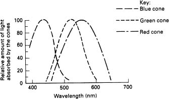
Figure 3.4 Sensitivity of eye receptors
Finally, our two eyes give us depth and the three-dimensional image of objects. We can however, be tricked by perspective so we need additional information. Generally this is produced by shading, for example, old silent movies illuminated largely in flat lighting, do not have the depth that the later monochrome studio films had in the 1940s and 1950s. The use of stronger keylights and backlights, copied from the film industry, enabled black and white TV to have some illusion of depth. Although the use of colour gives areas of contrast there is still a need for punchy lighting.
Adaptation and glare
The light sensitivity of the eye usually adapts itself to the illumination we are observing. A good example of this is coming from a fairly dark room into very bright sunlight and it doesn't take very long for us to adjust to the new conditions, although the light levels are incredibly different.
Adaptation requires a period of time to work and in fact requires a long time to get used to dark after light, more than 30 minutes, but on the other hand it does not take long to be accustomed to light after dark. There are limits to adaptation and this can be when luminance is so great that glare can occur. We have all had the problem of reading from white paper in a full summer sun, where the luminance value may be as high as 25 000 candela/m2, and although it may be possible to read under these circumstances it is very uncomfortable. Why do we suffer from this problem? It is caused because the eye is not a perfect optical instrument and can be affected by the scattering of the light rays which causes a high intensity source to be seen as if it were surrounded by haze. Where part of the retina is suddenly illuminated, the whole retina drops very rapidly in sensitivity (within 0.1 of a second). A good example of this is looking at a window which occupies part of the viewed scene which causes the eye to decrease in sensitivity and although the window may be reasonably clear, the remainder of the environment has become rather dark. Both of the above effects are very well known to the average motorist, either driving during the day when the road surface may reflect very bright areas, or indeed at night, the headlights of the oncoming vehicles. Unfortunately, as we all know, it takes some time for our eyes to readjust to normal after we have received sources which give us glare problems. There are two forms of glare; the first which impairs the visual performance is called ‘disability glare’ and the second, which can cause visual discomfort, is called ‘discomfort glare’.
Disability glare is caused by a bright source in the field of view, whereas discomfort glare is caused by excessively bright areas in the field of view and is usually caused by too high a difference between the dark areas and the bright areas being viewed. Generally, the luminance differences in the field of vision should not exceed 10 to 1.
We have tried to show in this section that although the eye is a marvellous instrument, it is not perfect. There is much that we do not know about its operation although the evidence so far shows that there is much in common between the eye, TV cameras and film cameras. In fact, it has been suggested that the coding system for passing colour information in the human brain is very similar to that used in the vision chain of any TV station.
3.4 Colour perception
The early philosophers, such as Pythagoras and Euclid, debated the nature of light and how the eye responded to a viewed scene. Theories went from a projected image from the viewed object which entered the eye, to the possibility that sensing rays went from the eye to the subject, rather like radar and that these rays would pass information back to the eye. We now know that most objects do not radiate any light waves whatsoever, and only convert the incident light on them into the shape, colour and appearance that we see. The two sensations we are most concerned with are the brightness and colour of an object. It was probably very fortunate for most scholars of today that Isaac Newton left Trinity College Cambridge when the university closed because of the plague and spent the next two years at the family farm. It was during this period of time that he focused his attention on the nature of light and subsequently produced his classic book ‘Opticks’.
Newton's experiments with colour were conducted by allowing sunlight to pass through a small hole in a darkened window. This beam of white light was passed through a glass prism and the emerging light spread out in a ‘spectrum’ of colours. The colours were red, orange, yellow, green, blue, indigo and violet. History tends to give Newton the credit for discovering the prism for this effect but this was not the case; it had been observed by scholars for many years. What Newton did was to take the original idea of splitting light via a prism and then use this to examine the colours coming through. By selecting one colour from the first prism and passing that colour through a second prism, he discovered that the second prism had no effect at all on the colour of the original light. He therefore concluded that colours were not the result of the prism changing the light but the fact that all normal white light contained the observed colours and the prism only acted to separate the colours. Having separated the colours out, Newton thought he should be able to return them back to the original white light source and by using an inverted prism after the first prism, he was able to re-create a white beam of light. Newton had experimented with coloured objects under the various sources of illumination and from these experiments discovered most of the concepts that enabled modern colour theory to evolve. For instance, he found that a red object would efficiently reflect red light but would appear very dark and nearly black when illuminated by lights of other colours. It was apparent to Newton that objects have colour because they reflect certain colours while absorbing the remainder of the spectrum. If we view the spectrum as split by a prism, as Newton did, we will notice that it does not contain all of the colours that we encounter in our everyday lives such as magenta or black and white.
Newton's theories caused a great stir in the world at large and one of the reasons for this was the fact the most human beings first learn about colour by painting. The lessons learnt from mixing the colours of paint are somewhat different to those for mixing the colours of light. It has to be realised that light is the source of all colour but pigments in paint are simply reflectors or absorbers of parts of the light that illuminates them. If a beam of red light and a beam of green light are superimposed the result is yellow. On the other hand, if we mix red and green paint we get rather a nasty looking ‘brown black’ colour. When using light, all spectral colours can be created by adding various component parts of the red, green and blue light and the system used is called ‘addition’, ultimately creating white. Pigments derive their colours by subtracting parts of the spectrum, therefore the system with pigments is called ‘subtraction’ and ultimately creates black (see Figure 3.5a and b).
The light from the sun and incandescent sources is generally white by nature and contains all the colours of the spectrum, however, as we will discover in other sections of the book various sources produce light by exciting portions of the visible spectrum to gain a response from the eye; but because they do not contain all the colours of the spectrum some distortion of colour can take place.
If we ring a colleague in Australia from England and we describe a red dress, they will have some idea of what we're talking about, a problem arises when we require our colleague to reproduce exactly the colour of the dress. How can we specify colour and its brightness accurately. One of the first attempts to define colour precisely was by an American called Albert Munsell in 1915, and his three-dimensional colour system is still in use today. The Munsell system enables three qualities to be quantified and these are:
1 |
hue |
Describes the basic colour such as red or blue; |
2 |
value (or brightness) |
Refers to how light or dark the colour appears (it is a measure of the amount of reflected light); |
3 |
chroma (or saturation) |
Refers to the intensity of colour; as a colour moves away from white it becomes more and more saturated. |
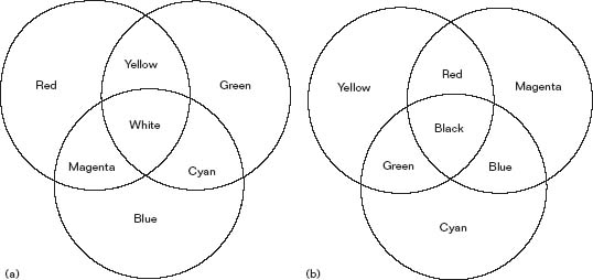
Figure 3.5 (a) Additive colour mixing; (b) Subtractive colour mixing
However the Munsell system is only as good as the illumination it is viewed in. We have all come across the problem of the piece of material that we're buying in the shop or the suit that we have selected which looks much better when we go to the doorway of the shop and examine it under daylight. We are also aware of how bad our skin looks under sodium street lighting. Coloured objects reflect light, the problem is that they don't reflect the entire spectrum of the light that falls on them or the light that falls on them is deficient in some way. The effect that the source of light has on any object is known as the colour rendering. In general, under normal illumination such as daylight, incandescent light, etc., there will be no problems, however discharge lighting (which may be fluorescent, street lighting or the type that we would use in studios or on location) will cause colour distortion by not having continuous spectral outputs. For instance, a green sample of cloth will only look green if there is green energy in the incident light. When we look in the manufacturers’ data on lamps, we will invariably find in the sections on fluorescent, discharge etc., reference to the colour rendering index.
Two approaches have been used to describe colour, the first uses standard colour samples such as the Munsell system against which materials can be compared. A second system is to analyse the light reflected from a surface and then assign a set of values which specify the colour. As we are now looking at reflected light we can use the primary colours of red, blue and green, giving a ‘tri-stimulus’ to the eye. The first system to try to define the colour by its spectral components was that of Newton, but Newton used seven basic primaries derived from his prism observations where from any mix of the seven it was possible to produce a range of colours towards white. One of the problems with the Newtonian system was that it didn't contain the entire range of colours, for instance lacking any reference to purple.
To be able to compile a very accurate system of colour specification, it was necessary to have a deeper knowledge of colour mixing, which unfortunately Newton did not have. He was also incapable of measuring light with the great accuracies that are required for modern colour measurement.

Figure 3.6 Spectral distribution
In 1931 it was decided by the CIE to develop a more accurate colorimetric system. To comprehend the system that the CIE adopted, we have to understand how metamerism works. The spectral difference between sources can be quite considerable as shown in Figure 3.6 where a stimulus consisting of continuous power throughout the visible spectrum is matched by three narrow bands of energy in the red, green and blue only. If we choose three primary sources of light which are derived from standard white light filtered by a red, a green and a blue filter, we can use these as standard sources for colour mixing. The CIE system is based upon using a standard observer who is seated in front of a white screen. On one half of the screen is projected some arbitrary light source, on the other half of the screen is projected a combination of our three primaries. The observer has to adjust the intensity of the three primaries until both sides of the screen match exactly in colour and brightness. Although the two halves of the screen now look the same, they do not necessarily have the same spectral composition. The amounts of the red, blue and green sources specify the colour that we are viewing but not the light itself. Those three numbers are unique to the colour observed.
The theory of colour matching is quite complex and the CIE set out to create a system that was relatively easy to use and understand. Figure 3.7 shows the three primaries chosen by the CIE and these are called ![]() ,
, ![]() and
and ![]() where
where ![]() corresponds to the red primary,
corresponds to the red primary, ![]() to the green primary and
to the green primary and ![]() to the blue primary. The green primary curve (
to the blue primary. The green primary curve (![]() ) shows the sensitivity of the human eye to light of different wavelengths and, as can be seen, the eyes’ sensitivity is at a maximum of around 550 nm but very poor towards the blue and red ends of the spectrum. By using the ‘photopic curve’, as it is known, as a ‘multiplier’ for any spectrum which is being analysed, we can calculate the apparent brightness. In other words, the source has much more energy than we are able to absorb.
) shows the sensitivity of the human eye to light of different wavelengths and, as can be seen, the eyes’ sensitivity is at a maximum of around 550 nm but very poor towards the blue and red ends of the spectrum. By using the ‘photopic curve’, as it is known, as a ‘multiplier’ for any spectrum which is being analysed, we can calculate the apparent brightness. In other words, the source has much more energy than we are able to absorb.
The X, Y and Z values are called the tri-stimulus values of the spectrum and the relative amounts of each give the colour and brightness of the viewed scene. To find X, we have to multiply the spectrum as measured, by the curve and the result gives the energy required for the stimulus. We would also have to do the same for the Y and Z values. The values of X, Y and Z are able to specify the colour accurately. The trouble is, it's very difficult when given these values to imagine what the colour actually looks like. We need a method by which we have an instant reference to the colour itself. The easiest way of looking anything up is to have a visual presentation, and in this case it is the CIE chromaticity diagram (see Figure 3.8). The diagram is another version of Newton's colour wheel system, thus as we did with the Newton system we can use the chromaticity diagram to analyse colours. Newton's original colour circle didn't include purple which is of course a combination of red and blue, but as can be seen we do have a purple line (see Figure 3.9). What has happened is we have plotted the spectrum locus on a graph which has an x axis and a y axis. The colour co-ordinates are derived from the following formula:

Figure 3.7 CIE primary functions

Figure 3.8 CIE diagram
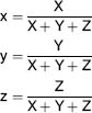
As the sum of x + y + Z will always equal 1, we only need two variables as the third can be determined from the other two. By convention, we use the co-ordinates x and y to describe the colour. It must be noted however, that those co-ordinates only specify the hue and the saturation of the colour but not its brightness. To ascertain the brightness, we have to use the value of Y, the green tri-stimulus value (photopic curve). As we move from the periphery of the colour locus towards the centre of our diagram, saturation of colours diminishes until we reach white. The centre of the colour locus which is positioned at the co-ordinates x = 0.33, y = 0.33, where the saturation has become zero. This point is known as equal energy white or reference white (colour temperature 9600 K).
In the laboratory we can do a spectral analysis of a source and then by using the CIE values compute the amount of X, Y, Z to give the tri-stimulus values. However, this method is not possible in practice, and conveniently for us hand held tri-stimulus meters have been developed which measure the values of the three primaries, do the computations for us and present the figures for the co-ordinates and brightness very neatly on a digital display.

Figure 3.9 (a) Newton wheel; (b) Modified by Harris
The CIE method enables us to do two things:
- 1 to analyse the colour of a surface, and
- 2 to analyse the spectrum of a light source coming to a surface.
Most of our use of a colour meter is to measure the colour of the light source, be it normal or modified by filters, etc. If we are examining the colour of a surface, then we need to know the colour of the reference source to reduce the variables to manageable proportions. The CIE adopted three standard light sources and these are:
1 |
Source A: |
This is a source typical of an incandescent lamp operated at a colour temperature of 2856 K. |
2 |
Source B: |
This source is typical of noon sunlight and has a colour temperature of about 4870 K. |
3 |
Source C: |
This represents an overcast sky or average daylight and has a colour temperature of about 6700 K. |
In 1965, the CIE introduced a system to regulate the colour rendering index (Ra). The system measures eight colour samples taken from the Munsell system, illuminated with a test source and this is compared with a reference illumination. The reference source has a value of 100, and due to the deficiencies in spectral output, the test source can at best equal or generally be less than the reference source and thus the Ra can never be greater than 100, and in most cases will be 90 or less (see Table 3.1).
Blackbody radiation
The scientists studying blackbody radiation discovered the following facts:
- The spectrum is continuous, just like the sun's and includes all the visible colours together with the infrared and UV spectra.
- When a graph is plotted of intensity versus wavelength, there is always a maximum intensity at only one wavelength.
- As the object becomes hotter, the wavelengths of maximum radiation become shorter.
- The hotter the object becomes the greater the total amount of radiation from a given area.
CIE general colour rendering index (Ra) |
Typical application |
Greater than 90 |
Where accurate colour matching is required, e.g. colour print inspection. |
80 to 90 |
Where accurate colour judgements are necessary and/or good colour rendering is required for reasons of appearance, e.g. shops and other commercial premises. |
60 to 80 |
Where moderate colour rendering is required. |
40 to 60 |
Where colour rendering is of little significance but marked distortion of colour is unacceptable. |
20 to 40 |
Where colour rendering is of no importance and marked distortion of colour is acceptable. |
Note: For film or TV use we would need an Ra index of at least 80.
Lacking the knowledge of today's scientists, their predecessors postulated the theory of a body absorbing all the radiation falling on it and to do that effectively, it would have to be black and hence the world was introduced to the term ‘blackbody’. What the scientists didn't know was that the blackbody was capable of radiation and although not commonly realised, every object radiates some light. The chair we sit on appears quite cool but in a room at 20°C, it is still 293° above zero Kelvin and according to the known laws of physics will radiate energy. Many modern surveillance systems actually look for radiated energy of low intensity. One good thing about blackbody radiation is that it starts in the very deep reds and goes to the very deep blues, passing through white in the process which, as human beings we happily accept. When we depart from the blackbody curve and approach green or magenta we are psychologically disturbed.
Figure 3.10 shows blackbodies at 2000 K, 3200 K, 5600 K and 6500 K. In addition to the visible spectrum, many other wavelengths are also radiated; the more the temperature is raised, the more energy and subsequently light is radiated. The curves also show a shift towards the blue end of the spectrum as the energy becomes greater. Modern incandescent lamps are very close to the blackbody radiation curve and in general are given a colour temperature to signify the colour of their light output. Incandescent lamps that we deal with have a colour temperature around the 3000 K mark. The sun is around 5000 K and light from the blue sky is generally from about 6000 K upwards.
If we wish to measure purely colour temperature, we measure the relative amounts of red and blue of the blackbody curve of the source in question. When the source deviates from the blackbody curve we would have to use a tri-stimulus meter so we can measure the green component.
Why is it that the discharge source is so different from that of the incandescent? Probably at some time in our lives, we have thrown an object into a fire and then been amazed at the magnificent colours produced when it burns. The colours are unique to the substance. In 1752 a Scotsman, Thomas Melvill, studied the light from a flame through a prism and discovered that the spectrum was not continuous. Some parts of the observed spectrum were bright and other parts were dark. When Melvill experimented with different chemicals burning in the flame, he found the locations of the bright and dark areas changed. From the early nineteenth century onwards the spectroscope was developed to enable researchers to examine the various colours generated within light sources. Each chemical element has a unique set of wavelengths and thus bright lines within its spectrum, and these can be used just like ‘fingerprints’. With the advent of electricity research was carried out on the effect of voltage when applied to gasses. During the latter part of the nineteenth century many different gasses were studied and their element lines were plotted, and it was discovered that some gases have thousands of lines and some have very few. Sodium in particular has only two lines in the yellow part of the spectrum, so close together they appear as one and this is the characteristic of many street lights that are in use today. Neon on the other hand, has very strong lines in the red and orange.
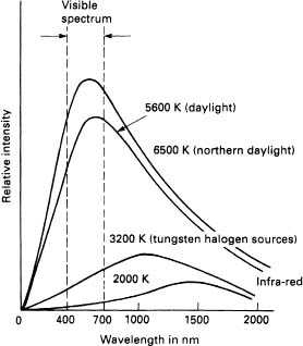
Figure 3.10 Continuous spectrum emitted by four typical blackbodies
Observing these bright line spectra was one thing, but to actually understand their generation was another. Ernest Rutherford, of atomic energy fame, was the first to postulate the theory of the planetary atomic structure. This theory suggests that the atom is mostly empty space, rather like our solar system and that the individual parts of an atom orbit a nucleus. The scientific theory of the time however, did not explain the existence of bright line spectra. In 1913, Niels Bohr a Danish physicist, set out to explain how the bright line spectra evolved. His theory was that the electrons occupied defined orbits around the nucleus; these orbits were governed by the amount of energy an electron had as it orbited the nucleus. If the electron was given additional energy by some means, the electron could be made to move to one of the higher levels within the atom. As well as moving, the excited electron had also become unstable. To regain stability, the excited electron would have to fall back to the lower level from whence it came and in the process lose the energy again, in the form of light.
Each element has a unique atomic structure and also has its own bright-line spectrum. When we view sources made up of several lines of energy we do not see the individual lines because our eyes integrate all the energy and tend to mix the colours together. However, it may be that the energy is not in the visible spectrum at all and is produced in the UV region. This energy while not directly visible is able to produce visible light by exciting certain chemicals and a good example of this is the fluorescent light.
Fluorescence occurs when a fluorescent molecule absorbs energy and emits light. Fluorescent lamps are a glass tube coated internally with a phosphor, which is a chemical substance with an energy structure that produces bands of colours rather than individual line spectrum. An electric current flows through the vaporised mercury in the fluorescent tube and in so doing excites the electrons. When the electrons fall back to the lower levels they release energy. Some of the energy generated is in the visible region of the spectrum but mostly it is in the UV and it is this UV energy that causes the phosphors to glow. It should be noted that higher energy sources can excite phosphors but lower energy sources are incapable, thus UV will cause the production of light but infrared energy cannot. Fluorescent tubes tend to have much energy at the blue end of the spectrum as well as nasty spikes in the green, and to balance their colour, combinations of phosphors are used so that the integrated light output approaches that of normal incandescent lamps. Thus we hear terms like ‘daylight’, ‘warm white’ etc. which are descriptions of their inherent colour, but not always of their colour rendering properties.
Tri-phosphor fluorescent tubes have coatings which produce narrow band energy in the red, green and blue regions and work by stimulating the red, green and blue receptors. By concentrating the energy into narrow bands it is possible to have tubes with a high light output. By adjusting the red, green and blue balance of the phosphors, various correlated colour temperatures can be produced. These tubes have been adopted for specialist use in TV and film luminaires as they have good quality colour coupled with low heat dissipation and a good lumens per Watt output.
The modern discharge sources such as the HMI and MSR, operate from the principles discussed, usually with an electric arc exciting mercury vapour and rare earth gases in various forms to give blends of colour. If we observe from its cold state a discharge lamp slowly warming up to its final operating temperature, we will see the discreet bands of energy joining in at various levels to form the colours that make up the composite output.
3.5 Spectral output of sources
Although the graphs in Figure 3.11 are apparently very different to each other, the various light sources all produce a sensation of white in the human eye. When a light source produces light at every wavelength in the visible spectrum it is considered a continuous source. Although these sources appear white as far as we are concerned, when objects are viewed under the various types of illumination, we get different responses. As a yardstick, it would be nice to have a source that gave a perfect white, and such a source wouldn't show any imbalance towards the red, the blue or the green of the spectrum, and would contain equal amounts of each. This source is called an ‘equal energy source’ and has been discussed in reference to the CIE system.
All blackbody sources are continuous radiation sources and although biased heavily either to the red or the blue according to the temperature of the radiator, the colour distortion is at a minimum. The interesting thing about continuous sources is the fact that nature has provided sources of this type from time immemorial and all the light derived from hot objects, such as candles, oil lamp, wood and coal fires, obeys the laws of the blackbody radiator. It is only in recent times that sources of a different type have been developed for use by mankind; the reason being more light for the power consumed and is usually a consumer led development by lamp manufacturers. Probably the most well known of these is the fluorescent tube. One advantage of using mercury discharge sources was that they provided high efficiencies of light output. In the earlier days of discharge lamps however, quantity was put very much before quality. In the basic mercury discharge lamp, radiation is mainly found in the blue, green and yellow sections in very narrow band spikes and obviously does not give a good colour response. Typical examples of basic discharge lamps are those used in street lighting and some forms of crude floodlighting, which tend to be either rather blue or predominantly yellow. To improve the colour of the light source, it is necessary to introduce elements such as tin, indium, sodium, lithium and scandium. One of the problems with using some of these elements is the fact that they could react with the silica envelope and rapidly destroy the lamp. In practice, by using metals in the form of their halide salts (hence the name metal halide lamps) most of the problem is overcome. The table below gives examples of the radiation that can be produced with the various elements:

Figure 3.11 Spectral distribution curves of four common sources
Tin |
orange/red radiation |
Scandium |
blue and green radiation |
Sodium |
yellow radiation |
Thallium |
green radiation |
Lithium |
red radiation |
By selecting the various metals and metal halides that can be used, we can introduce more spectral spikes into the characteristic and eventually end up with colour rendering of a very high order, such as those in HMI and MSR lamps.
3.6 Filters
We will discuss in other sections the need for the almost apparent perfection of the white light that we use either for daylight matching or for incandescent source matching. In this section we shall talk mainly about distorting the colour of light.
The choice of colour to create the required effect or mood in theatre was established from very early days by placing a coloured glass or silk in front of the light source. In 1858 Covent Garden introduced overhead gas battens running the width of the stage, and providing colour change by stitching together two foot wide lengths of gauze coloured red, green and blue which could be pulled around the gas batten to produce the required colour. Alternative materials were silk, calico or tammy. A high price was paid for early experiments with lighting and the attempts to provide colour. Theatres caught fire and many people died, it is therefore no wonder that the Fire Officers of today insist that all materials used as colour filter must pass the appropriate safety tests.
Early colour filter material was made of gelatine dyed to the required colour. This offered an enormous range, but suffered the problem of handling. As it dried out, it would become very brittle and virtually shatter and fall to pieces and of course, presented a fire hazard. However, the use of gelatine filter persisted into the 1960s. The advent of electric lamps in the late 1890s provided another possibility for colouring the light by dipping the lamps into coloured lacquer. This provided an excellent choice of colours but, of course, it could not be changed once the lamp had been coated. With the introduction of the incandescent tungsten filament lamp in the early 1900s, the heat was to prove too much for the lacquer coating for anything other than low wattage sources. This led in the early 1930s, to the introduction of a new colour material made from cellulose acetate by a complicated method of shaving thin sheets from a large block of the dyed material and polishing the sheet until it became a transparent colour filter. This type of filter persisted for many years but has been replaced by plastic materials that can be coated with the appropriate colours on a continuous production method of manufacture.
The two main colour filters in use today are polyester and polycarbonate. Both are suitable for tungsten halogen luminaires and both have their attractions. Polyester is normally cheaper but does not last so long, and the polycarbonate tends to justify its price by the reduction in replacement costs and the time involved. Both materials are available in over 100 colours and hues and can even be used by adding colours in the same luminaire to create your own special shade for the LD who can't find the one he wants in the swatch book.
Glass filters have always been used and are still in use today. However, after the initial euphoria over the fact that the glass filter does not fade or burn out, one soon finds that they are so restrictive that they are not a very practical solution. The colour restriction is caused by the glass manufacturer requiring the lighting filter stockist to order what is known in the glass industry as a ‘melt’ which could be about one tonne, but of course, it is all one colour which will supply his customers for years. Unfortunately, any one particular melt cannot be guaranteed to match the next melt, therefore some permanent applications such as cyclorama backings that were thought to be ideal for glass filters, were faced with changing all of the filters when replacements were required, because the new colours stood out from the rest. An additional problem with the glass filter is that they can shatter if they are unevenly heated, causing a safety problem when used in overhead luminaires.
In general, the filters used for TV, film and stage are essentially types of plastic with dyes in them. Other specialist filters can be produced and these are dichroic layers on sheets of glass. Dichroic filters work by having a very thin layer of a chemical deposited on a piece of glass. The thickness of the surface coating will be one quarter of the wavelength of the light concerned and is obviously extremely thin. The filter works by reflecting selected wavelengths within the spectrum and if a blue dichroic filter, such as the type used with small luminaires, is examined, it will be found that one surface reflects yellow in large amounts. Dichroic filters rely upon the light being perpendicular to the surface of the glass due to the need to keep a precise quarter wavelength for the selection of the colour to be reflected. Light incident from other angles will be affected in different ways, thus it is possible in practice to see a slight variation in colour over the width of a light beam when using dichroic filters. This problem could be solved by curving the filter surface so that all rays are normal to it.
Manufacturers of dichroic filters are able to tailor the surface coatings very precisely to select portions of the electromagnetic spectrum, particularly with infrared and UV where the division between the visible light and the harmful rays is very narrow. A good example of dichroics are the infrared reflectors used on cold lamp sources in projector systems and in many of the low voltage sources used in shop displays and architectural lighting (see Figure 3.12).
In the past, specialist dichroic filters were produced mainly for luminaires such as the Redhead and Blonde for ‘tungsten to daylight’ conversion. The heat resisting glass on which the dichroic coating was deposited, had to be carefully selected, to take account of the heat differential from the edge of the glass to the centre of the glass. This means that the co-efficient of expansion of the glass chosen has to be very small. The glass substrate is approximately 3 mm (0.125″) thick. One problem with manufacturing dichroic filters, is that the evaporation chambers can limit the physical size of the area of the filter, and the Blonde dichroic was probably one of the largest made. The dichroic coating has to be absolutely uniform to prevent colour changes over its surface. One advantage of dichroic filters is that their colour lasts much longer in use; therefore they are ideal for low maintenance installations. The colour range at the present time is limited to around 20 colours, but in the future, this will no doubt be expanded. It is, of course, possible to use a combination of filters to produce a fairly wide range of colours but for each filter there will be an insertion loss in the optical chain so the overall result might be quite inefficient. Dichroic filters can be used for ellipsoidal spotlights, PAR units and smaller spots such as the MR16s. They come in a range of standard frame sizes to suit various applications and are as follows:

Figure 3.12 Cool light reflector
Filter size |
|
Millimetres |
Inches |
254 × 254 |
10 × 10 |
190 × 190 |
7½ × 7½ |
86×86 |
3 |
50 round |
2 round |
One of the problems for manufacturers of dichroic filters is to match the very wide range of polyester filter materials available on the market. Whereas in the past 1 and 2 kW sources were often used for profile spots, with the more efficient lamps and luminaires in use today, the heat from the lamp has been considerably reduced and is approximately 25–33% of the old type. This means that plastic filters will last much longer in use. The cost of dichroic filters is also generally higher than the equivalent plastic ones which means that unless there are strong reasons for using the dichroic type, plastic filters will predominate for a long time to come. Dichroic filters are used in vast numbers in the moving light industry to produce a wide range of colour effects. In this case they are chosen mainly for their long life.
Many books have been written on the subject of the use of colour to create the right mood and setting from joy to sadness, from shock to restful security. However tempting it is to pursue this course, we must confine our studies to producing the colours for the LD to use and the simple physics involved to achieve the desired effect. The LD has two variables to consider:
1 the colour of the light, and
2 the colour of the subject.
He has total control of the first variable but the second is completely beyond his control and must be determined at an early stage of planning if he is to achieve the desired artistic effect. The correct colour of costumes and scenery must be used during the rehearsals when the colour filters are being chosen or disaster will result.
As human beings we tend to associate reds and yellows with bright and breezy situations and blue with much more sombre occasions, red is also associated with daylight and blue with night.
Originally very few filters were produced for effects purposes, but over the years manufacturers have come to produce vast ranges of subtle colour filters. Most of these, we suggest, are required by the individual foibles of the lighting practitioners and not necessarily by the requirements of the viewer. It is our experience that most practitioners of the art of lighting tend to do things on a trial and error basis when selecting filters.
Other types of filter required in the lighting industry are the kind that either change the colour of the light source itself, or change the colour of the viewed image as seen by TV, film or photographic cameras. It must be said at this time that any filter which changes the nature of the light cannot necessarily be designated as a particular colour filter, a colour temperature changing filter or any other type. A filter essentially changes the colour of a light source and therefore could be used for any purpose where the resultant colour may be required. What is extremely important, for the purposes of this book, is how do we achieve good filtering, and at the same time keep a high transmission level so we do not waste large amounts of light. It also has to be remembered that a filter called ‘Bright Rose’ looks decidedly not ‘Bright Rose’ when put in front of a predominantly blue source.
A good filter should only be interested in the visual energy, i.e. that from 400 to 700nm. A perfect filter would only remove that portion of energy in which we are interested in a very precise way. However filters cannot be made to this sort of tolerance and generally have some form of overlap and thus remove other bits of energy from the light beam. When light falls on any material, three things occur, some light will be reflected, if the material is translucent enough some light will pass through the material and some of the light will be absorbed within the material. The absorbed light will be converted to heat energy. When the majority of the light is either reflected or transmitted or a combination of the two effects, the smaller quantity will be the heating effect. To illustrate this effect, white and other pale coloured materials usually reflect most of the incident light. For example most people will wear lightly coloured clothing in the summer which reflects most of the energy in the sunlight but we generally wear dark coloured clothing in the winter to keep us warm. The black telephone sitting in the sunlight on our desks has an extremely low reflectance and it also transmits little or no light. Consequently the telephone gets rather hot, which may be good news for the telephone company's replacement programme, but is not so good for the user.
When we wish to change the colour of a light source for effect or colour correction, we will invariably put some form of coloured filter in the light path. We cannot introduce a colour that is not present in the source. The colour of the emerging light from the filter depends upon the spectrum of the incident light striking the filter and on the characteristics of transmission of the filter itself. As well as the colour of the emergent light from a filter we will also be very much concerned with the quantity of light the filter lets through, otherwise known as the transmission. A filter works by subtracting selected portions of the spectrum away from the light source. If we start with the same amounts of red, green and blue light in the light source, and our filter takes away the green component, we are left with the red and blue, which when mixed together gives magenta. Thus our magenta filter can also be called a minus green filter. A yellow filter would allow the red and green portions of the spectrum through, taking away the blue, thus it can be called a yellow filter or a minus blue. A cyan filter allows the blue and green light through and stops the red portion of the spectrum, therefore a cyan filter is also a minus red.
So far, we have looked at removing one colour, if we remove two colours we can then produce our three primary additive mixing colours used for lighting, i.e. if we remove the red and blue components we are left with green. The removal of red and green gives blue] finally if we take away the blue and green we are left with red.
As will be realised, the filters we have just given as examples have the ability to subtract light away from a portion of the visible spectrum, it will also be obvious that we are looking at a subtractive light process. The amount of light transmitted by any of these filters will be determined by the density of colour of the filters which is determined by the thickness of the colour layer. By using combinations of the basic magenta, yellow and cyan filters, which are often used in photographic processes, in various thicknesses, almost any colour can be produced (see Figure 3.13).
The alternatives given in Table 3.2 for red, green and blue show the two methods of achieving the same result.

Figure 3.13 Subtractive filters: (a) Yellow; (b) Cyan
A fine example of the two principles of additive and subtractive colour was demonstrated by Adrian Samoiloff in the 1920s when he had a stage act of illusions created with coloured light and selectively coloured subjects; one of which was to make the actor up in red cosmetics and wearing a coat of black and blue/green stripes. The actor would first be illuminated using a red filter when he would appear to be a white man in a black coat, and then illuminated with a blue/green filter, he appeared to be a black man in a striped coat. This effect can be very interesting by design but quite a disaster if created by accident.
Desired effect |
Filters required |
White |
None |
Black |
*Yellow, cyan, magenta |
Red |
Yellow, magenta or (-blue, -green) |
Green |
Yellow, cyan or (-blue, -red) |
Blue |
Cyan, magenta or (-red, -green) |
Note: *In other words removing all the light from the source.
When we use two filters to produce a result, what has happened is that the original incident light has been modified by the characteristics of the first filter and consequently the emergent light from the filter is modified by the characteristics of the second filter. The transmission has also been affected and working this out is relatively simple, because if half the light was removed by the first filter and half of this light passed through the second filter, we would have ended up with a quarter of the original light. By this simple example it can be seen that the transmission can be down to quite low percentages on some colours; particularly when we are using primary transmission colours. Colour filters for light sources are usually produced with specified colours in various densities to meet the needs of the LDs. Some luminaires used for colour effects, which have a single light source, have to use combinations of yellow, magenta and cyan filters to achieve their results. A close examination of some manufacturers’ filters particularly in the yellow range, will reveal that a medium yellow filter could be made up from two or more sheets of less dense yellow filters. Other than the need to remove portions of the visible spectrum for effects purposes, there is on occasions need to remove the UV and infrared energy from the spectrum. For example, when filming in museums, special precautions have to be taken to remove much of the infrared and UV portions of the spectrum from the light sources to avoid contaminating the colours on valuable paintings and objets d'art.
Colour temperature correction filters are those that change the balance between the red and blue portions of the spectrum only. To change a source from 3200 K to 5600 K means that the red end of the spectrum has to be diminished; therefore there is a higher balance of blue to red in the filter. To change a 5600 K source to 3200 K, an orange correction filter removes part of the blue from the light beam to achieve a correct red/blue balance.
We need to use coloured filters to correct the output of light sources in one of two ways. It may be that we have a 3200 K source that requires to be raised to 5600 K to be used with daylight sources. It could be that we are using a source of 5600 K and this requires correction down to 3200 K. A problem that exists with filters is the fact that they cause a definite change and are dependent upon the light source for the resultant colour output. A blue filter placed in front of a 3200 K lamp would create much less change than if it were used to filter a discharge source. As this is the case, we can hardly label a filter as a 2000 K correction filter. Luckily for us, there is a way around the problem and we do this by using ‘micro reciprocal degrees’. Suffice to say that a filter will cause a constant shift in the reciprocal value of the colour temperature of the source. To make the maths easier, the reciprocal value is multiplied by 1 million, and thus mired stands for ‘Micro REciprocal Degrees’. Thus a colour temperature of 2000 K is equivalent to 500 mireds and 4000 K equates to 250 mireds. A filter which changed the light from the source from 2000 K to 4000 K would thus produce a change of –250 mireds. This filter can be designed so that it always produces the change of –250 mireds, irrespective of the original source. Note that filters which decrease the colour temperature of sources have positive values, but filters which increase the colour temperature have minus mired shifts.
If we look at some examples, they give a good idea how this system can be used in practice.

Note that although the same filter has been used in examples (2) and (3), the Colour Temperature change in (2) is 967 K and in (3) 1600 K.
One type of filter that we require which would fail in its task if it changed the colour of the light in any way, is the neutral density filter. Its very name indicates its purpose, it has to be absolutely neutral and diminishes only the quantity of light and not the colour of light. It generally has two purposes, one of which is to diminish the amount of light entering the camera lens or it can be used to filter the light coming through windows and other apertures to allow a balance between a mixture of natural light and artificial light on any scene.
All the foregoing comments have been made with regard to light that was basically white in content on entering the filter. If the light entering a filter was essentially magenta in colour and filtered by a green filter, the result would be no light, as the green light has already been removed and the green filter would just remove the red and blue components of the magenta. This is obviously an extreme case but can serve to illustrate the need to be careful when filtering light sources.
3.7 Conversion of light in film and TV cameras
One only has to go to various TV viewers’ homes and see the adjustments made to individual receivers to realise that opinions on what constitutes good colour vary quite considerably, therefore before we progress any further, perhaps it would be wise to declare the main objective in the reproduction of colour in any system of image transference. This objective must be that if we were able to look at the reproduced scene, side by side with the original, there would be very little difference between the two.
Whether light is a wave or a particle, there is no escaping the fact that light is a form of energy, similar to heat, electrical, mechanical and nuclear. In nature energy changes from one form to another. The energy conversion we are most interested in is the conversion of light, either into chemical energy, such as in the eye or in the process of filming, or by the photons that are guided by a lens to the electronic receptors in our TV cameras.
Modern 35 mm film emulsion can withstand enormous exposure latitudes and to some extent colour distortion. We as professionals in the entertainment field, must have standards to adhere to and as boring as it may seem, these usually involve a scientific measurement or some form of discipline in operational procedures. Whether we are going to produce negative film or reversal film the basic system is the exposure of three layers of emulsion to red, green and blue light. Those layers are inherently superimposed within the emulsion itself. It is of course possible to individually process the red, green and blue light arriving at the film by using three separate film stocks, and this was the basis of the old Technicolor system used from 1932 to 1955. One of the problems with using three different stocks for the red, green and blue components is that although it is easy to separate the constituent colours, the superimposition of the three images to reproduce the final image is somewhat difficult and requires a high degree of precision. Even with the Technicolor process, the final copy of film sent to the cinemas for projection was multilayer film stock. Although cameras have an iris exactly the same as the eye, we can only reduce the amount of light hitting the film, we cannot increase the light level above the largest opening in the iris of the lens. If we wish to have greater sensitivity, we have to change to a different type of film. As a general rule, the more sensitive film becomes, the greater is the granular structure. The reason for using larger grains in the film is that they stand a higher chance of being struck by the photons. This use of a larger grain structure is similar to the grouping of the rods in the human eye. In the case of the eye, and in the film, the sharpness of the image reduces with the need for greater sensitivity.
The exposure of film to light causes the photons to strike the silver halide crystals in the film emulsion and these will change according to the intensity of the light. Photographic emulsion is naturally sensitive to the blue part of the spectrum; to increase the sensitivity to the green and red layers sensitising dyes have to be added to the emulsion. If we use the basic emulsion as the top layer in our system, it will be sensitive to the blue part of the spectrum and because of this fact we need no filter for the blue input from the lens. Because of the sensitivity of the other two layers to the blue, we reduce the blue going through the film by having a yellow filter immediately beneath the top layer. If the bottom layer is made sensitive only to red light we will not need a red filter. Between the yellow filter and the red emulsion is the green emulsion. As the blue light has been prevented from reaching this emulsion, which is sensitive only to the green part of the spectrum, we do not need a green filter. By constructing the film this way, we have effectively had three single exposures for the red, green and blue but all taken at the same time and in perfect register. Also by allowing the longest wavelengths to travel the furthest through the layers, we reduce the tendency to scatter, which causes lack of resolution.
The film is now processed so that cyan, magenta and yellow images are formed in the three layers. This is typical of negative film stock. To produce the positive from this stock, it is basically only necessary to photograph it with a similar type of negative, although in practice very sophisticated films can be used for the reversal process. Films can be balanced for artificial light or daylight and this is accomplished by the balance between the red and blue emulsion sensitivity. Figure 3.14 shows the difference between negative film for daylight and negative film for artificial light.
As can be seen, this film is composed of three emulsion layers being sensitive to red, green and blue light along with a protective layer, a yellow filter layer, an anti-halation layer and other layers, all coated on a clear safety base. The other side of the base is coated with a black resin backing to provide such properties as anti-scratch and anti-static. It also provides for lubrication so that its passage through the mechanical system is made easier. Different couplers are incorporated in the various emulsion layers and through post exposure processing, colour dyes and mask images are formed in the emulsion (see Figure 3.15). The film contains an orange coloured mask which allows for correct colour rendition when prints are made through this negative material on a positive film.
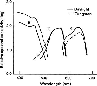
Figure 3.14 Film comparison (courtesy of Fuji Film Co. Ltd)

Figure 3.15 Negative film layers (courtesy of Fuji Film Co. Ltd)
Television cameras have to analyse the light from a scene and the method is somewhat different to that used with film. The charge coupled devices (CCD) used in cameras have the same colour sensitivity, and are therefore not adjusted for the individual red, green and blue components of the light. Secondly, there are no commercially available sensors capable of producing the red, green and blue signals in a single device as required for the process of high quality broadcast colour TV. A fundamental requirement for broadcast TV standards is that three individual sensors have to be used together with colour filtering systems. Thus, the use of the three colour sensors and the consequent splitting of light that has to occur makes the colour camera optically very complex. Light falling on the three sensors must have a common entrance, i.e. each sensor must see exactly the same scene in order to avoid optical distortion. When processing the light through the optical system this has to be done with minimum loss, avoiding either excessive lighting levels in the studio, or producing noisy pictures by not having sufficient light to satisfy the sensitivity of the camera sensors. Most of the optical requirements with the systems for colour cameras can be met by using zoom lenses to create a single path from the viewed scene to the camera electronics. The diagram shows a typical beam splitting system to derive the red, green and blue components (see Figure 3.16).

Figure 3.16 CCD splitter block
What is a CCD? A charge coupled device is a solid state chip covered in several hundred thousand photosensitive cells, all of this built onto a device roughly a centimetre square. Each photosensitive cell represents one piece of picture information (pixel). Like camera tubes, CCDs have the same colour sensitivity, therefore three devices and filters for the red, green and blue components have to be used. As the CCDs are built to an absolute, almost perfect matrix, there is a lack of geometric distortion in pictures. The three chips have to be positioned extremely accurately so that the individual elements are aligned to an error of about half a pixel. If a registration accuracy of 0.05% is required, this means the alignment must be accurate to two thousandths of a millimetre which can only be accomplished by the camera manufacturer. If we are aligning the chips on the prism block to this degree, it is not difficult to imagine that heat can pose a problem. Temperature differences within the optical block will obviously cause misregistration, due to different coefficients of thermal expansion. One advantage of this system is that having been aligned in the factory, the system will not drift out of tolerance. A further tremendous advantage of CCDs is that they have a superb colour response although a problem is that the peak sensitivity is in the infrared region. This has to be corrected, otherwise we would have problems with the reds in the system, and an infrared ‘cut off filter’ is fitted to the optical path to do just this. A major advantage of CCD systems is that they are more sensitive (around 250 ASA) than tube systems (about 64 ASA) and this has allowed the incident light level in studios to be reduced from 1600 lux to between 300 and 800 lux, dependent upon the type of production.