
5
Aesthetics and Environmental Integration
5.1 Introduction
The roles of aesthetics and environmental integration in bridge design are recognized nowadays as key parameters in any design or design and build tender. Cost and execution methods are no longer adopted as unique parameters for comparing different bridge solutions. Aesthetics is taken into consideration like other criteria related to structural, execution and durability aspects.
Design options must reflect equilibrium between functional requirements, structural safety and durability, cost, planning for execution, aesthetics and environmental integration. If most of these aspects may be compared on basis of objective criteria, aesthetics, and environmental integration may be quite subjective. Apart from this, an even more difficult aspect to define is the ‘weight’ of an aesthetic parameter to compare bridge solutions.
The ‘cost of aesthetics’ in a bridge project is not easy to define even if some attempts have been made. Minimum values in the order of 10% have been mentioned [1] as very often accepted in design‐built competitions. However, this aspect can not be accepted without taking in to consideration the bridge site and the way the bridge is seen. An urban bridge requires more aesthetics requirements than, for example, a highway viaduct integrated in a site where bridge views are rare. Bridge design should therefore be the outcome of scientific and technological progress respecting integration in the environment and aesthetic perception of structural forms. Engineering sensitivity discussing and taking into consideration environmental issues has very much increased in last few decades.
A series of basic concepts on architectural aspects of bridge design may be formulated from design practice. Even if considered as common sense rules of aesthetics and landscape integration, they may be useful as design guidelines. Design cases to illustrate aesthetical design rules are taken only from authors design experience. This avoids any aesthetic appraisal on bridge designs from other authors, since aesthetics is a subjective aspect. The reader is adressed to the excellent references [2–4] on the subject, for many other design examples.
As a basic rule, designing a bridge should not be a simple structural exercise; bridges should reflect the art of structural engineering [1, 5] and environmental integration. The reader is referred to more general aspects on architecture [6] and texts on specific projects [7–11] and some outstanding works on the “art of structural design” [12].
5.2 Integration and Formal Aspects
The development of the design concept requires understanding environment integration aspects from formal aspects. The former includes the scale of the bridge in the landscape and the way span arrangement, location of the piers and geometry of structural elements are integrated with the landscape and the environment.
The last, formal aspects are concepts of slenderness of the deck, ‘transparency’ of the substructure, namely the impact on the landscape of forms and proximity of the piers, or even more detailed aspects such as fascia beam forms, handrails and lighting posts.
5.3 Bridge Environment
Understanding the bridge environment requires understanding how the space/landscape is occupied by the bridge. A main issue is: what is the relationship between the ‘scale’ of the bridge and the ‘scale’ of the bridge site?
The horizontal and vertical alignments, after the bridge location decision is taken, are the most important aspects for site bridge integration. The level of the bridge deck is a key parameter when the bridge is located near a small village. A deck at a high level will require large spans and the general layout of the bridge results in a ‘scale’ unbalanced with the ‘scale’ of the village. On the contrary, when the bridge is located in a deep valley (Figure 5.1) a high level deck requires a reduce number of piers and a good balance with the landscape.

Figure 5.1 A bridge located in a deep valley. The João Gomes Bridge in Funchal, Madeira Island (main span of 125 m, deck at 140 m height from the river bed).
(Source: Courtesy GRID, SA)
Urban bridges are often more difficult for environment integration. The location of the piers is usually constrained by existing roads, railways or any other type of existing construction. The vertical alignment may induce reduced vertical clearances and a deck of ‘high slenderness’ defined as the ratio l/h, where l is the span length and h the depth of the bridge deck. The situation is even more difficult when the in plan alignment is curved due to local constraints, as already discussed in Chapter 2 (Figure 2.14).
Simple sketches on photographs of the bridge site may be useful tools to approach the main issue about the landscape integration of the bridge. In Figure 5.2, the scale of a suspension pedestrian bridge, with triangular towers and a single main cable suspending a thin precasted concrete deck, designed to be built on a sensitive environment, is approached in this way. By adopting a self‐anchored suspension bridge the impact of the abutments and cable anchorages were avoided. The deck is suspended from the main cable through inclined hangers with a triangular geometric arrangement such as a Warren truss. From Figure 5.2 it is possible to assess the scale ratio and affinity between towers and trees and from span deck length and scale of the river. New computer technologies may be adopted to develop renderings of the bridge inserted on topography and landscape. Some examples have been shown in previous chapters (Figure 2.1). These 3D models allow study of the ‘bridge scale’, its volumetric occupancy in the landscape and the integration of the super and substructures on the site.

Figure 5.2 Bridge scale and integration with the environment. A sketch and a rendering for a pedestrian bridge proposed for a design competition in Serbia Republic.
(Source: Courtesy GRID, SA)
A basic issue is, what is the impact of the structure on the landscape/environment? There is no simple answer for this question since, in some cases, it may be justified to design a bridge ‘aesthetically detached from the contest’ to be built as a landmark; in other cases there is no need for it – the structure holds by itself [5].
5.4 Shape and Function
A basic concept for bridge aesthetics [2, 3] is ‘shape follows function’. In bridge engineering, the bridge geometry is quite often the result of structural requirements and the execution method. Some examples are:
- The parabolic depth variation of continuous bridge decks (Figure 5.3a), consistent with its function to large bending moments at support sections and at mid‐spans;
- In a frame bridge with inclined piers (Figure 2.1), articulated at the foundations and monolithic with the deck, the piers cross section should be reduced from the top to bottom;
- Bridge structures may be adopted with constant height decks (Figure 5.3c), even with large span lengths, if the height (h) of the deck above the ground is large enough to avoid a negative appearance.

Figure 5.3 Shape and function. Geometry of continuous bridge decks consistent with the shape of the permanent bending moment diagram: (a) Parabolic, (b) linear and (c) constant deck height solutions.
Shape and function may result, as stated, from the execution method. For example, when the deck of a segmental prestressed concrete bridge is built by a balanced cantilever scheme, large bending are developed at support sections during erection; the mid‐span sections have much lower permanent bending moments and may have a height less than half of the depth at support sections. However, when a concrete bridge deck is executed by an incremental launching scheme or by a formwork launching girder, a constant depth girder deck is the most convenient one. Of course, the adoption of one of the previously mentioned execution schemes is dependent of the span lengths adopted. For the balanced cantilever scheme, the spans are usually in the order of 60–200 m, while for incremental launching or for formwork launching girders, spans lengths are cost‐effective for 30 and 60 m spans.
The longitudinal layout of the bridge is a key aspect for aesthetics quality. Taking the three span bridge in Figure 5.3, a variable parabolic depth is quite often the most convenient solution. A bridge with a linear variable deck near support sections may also be adopted. Comparing the three solutions in the figure, solution (c) is the most easy to execute and solution (a) the most complex one; option (b) represents a compromise. For the case of constant bending stiffness decks (EI = const) and l1 = 0.7 l one has M1 = 0.4 M0 and M2 = 0.6 M0. For option (a) it is quite convenient to adopt a depth d0 of order 1.3 d1–2.5 d1 and the parabolic transition at the end span should be made at a distance c = l/2. If the deck is built by a ‘balanced cantilever scheme’, the rule c = l/2 is relevant for the equilibrium of the cantilevers during execution. All these examples show how the execution scheme may affect the layout in elevation of the bridge influencing its appearance.
For a bridge over a river (Figure 5.4) with a deck not too high from the water the appearance improves for large ratios d0/d1, say between 2 and 2.5, yielding an ‘arch’ shape to the superstructure.

Figure 5.4 Bridges with continuous decks and approach viaducts.
For the case of low longitudinal alignments with decks with large depths at the support sections (Figure 5.4), the width b of the piers should be much larger than the width strictly necessary from structural requirements.
A large pier width yields a stable appearance for the bridge and a quite good aesthetic equilibrium with the deck at support sections. If the bridge deck is not continuous with an approach viaduct (Figure 5.4), the apparent ‘continuity’ of the depth of the deck, at the transition piers, is quite important for aesthetics. A discontinuous variable depth at transition piers (Figure 5.5) should be avoided.
Figure 5.5 Discontinuities at the transition piers.
The concept of ‘form follows function’ is not restricted to bridge decks, as already exemplified for the piers of the portal frame in Figure 2.1. The shape of the piers influences the bridge appearance [1]. Vertical, inclined or V‐type piers may be adopted as required by the span length or for aesthetics. In Figure 5.6 the V‐shaped pier at the roundabout has been adopted to reduce maximum free span lengths to 41 m to improve the visual slenderness of the deck. This has also been made to reduce the weight of the precasted girders. The deck is transversely made of three precasted concrete bridge girders with a U shape cross section. The central V shaped pier turns out to be the landmark for the roundabout.


Figure 5.6 The use of V shaped piers in a viaduct in a roundabout (approach to Lisbon airport) to reduce the span lengths of concrete precasted U girders.
(Source: Courtesy GRID, SA)
In Chapter 2 (Figure 2.2) another example was shown where V shaped piers have been adopted to allow a slender box girder deck, reusing the formwork of another bridge of the same roadway project, with 42 m span lengths. The V shape piers at a 60 m distance (at the foundation levels) allowed the free span lengths to be reduced to 42 m.
5.5 Order and Continuity
The concepts of ‘order and continuity’ plays a relevant role in bridge aesthetics, namely for the layout and span arrangement. The case of Figure 5.4, where two different sequences of span lengths are adopted, shows the importance of ‘visual continuity’ of the bridge deck, that is, a bridge deck for the approach spans with the same depth d1 of the main bridge at the end span. Of course, d and d1 depend on the execution methods adopted for the approach bridge (or viaduct) and the main bridge. An expansion joint is adopted between the two bridge decks but a smooth transition, like in Figure 5.4, is always the best option.
The span arrangement should be selected as a function of the execution method, but also as a function of the longitudinal alignment. In a deep valley, span lengths should decrease (Figure 5.7) from the centre to the end spans. The span length/pier height ratio (li/hi) should remain approximately constant at all spans. This condition should be applied for the views of the bridge under its normal service conditions. That is the case of the long bridge (1230 m) in a dam shown in Figure 5.8, where (li/hi) ratios at the bridge sites before the dam was built, were very much different from the ‘service’ conditions. The water table yields an approximately constant (li/hic), where hic is the vertical clearance at usual water table levels.
Figure 5.7 Span arrangement for multiple span bridges in deep valleys, from the centre to the end spans keeping the ratios li/hi approximately equal.


Figure 5.8 Bridge over the Guadiana River at the Alqueva Dam, Portugal: renderings before and after the dam has been built.
(Source: Courtesy GRID, SA)
5.6 Slenderness and Transparency
The concept of slenderness may be tied in to the deck or to the piers. Slenderness may be defined as the (span length/depth of the deck) ratio or the (height/cross section dimension) ratio of a pier. Hence, one refers in bridge aesthetics to the slenderness of the superstructure (deck) or of the substructure (piers and abutments).
For roadway superstructures, l/h ratios at mid spans of continuous box girder decks may be as large as 40 or even 50 at mid span sections, provided at support sections, over the piers, lower values are adopted like 17–22. Constant height decks have l/h ratios in the order of 15–27, values depending on the method of execution. For example, for incremental launching of a concrete box girder of constant depth, low values (14–16) may be needed while for the same bridge deck type when executed with a moving scaffolding, a value l/h between 17 and 20 may be adopted.
However, if the incremental launching method is adopted for a composite bridge deck, the slenderness of the deck steelwork may reach 22–27. One relevant aspect when defining the deck slenderness is the height of the deck above the ground.
If the height of the bridge deck to the ground is too low, as is usually the case for urban bridges, the deck slenderness should be increased, as much as possible, for aesthetics. When the height is quite large, for example, a bridge in a deep valley, the slenderness of the deck is not so relevant. The concept of ‘apparent slenderness’, that is, the slenderness as detected by the viewer, is related to the apparent depth of the bridge deck. The apparent slenderness increases with the inclination with respect to the vertical of the webs of a box girder; larger inclination, say slopes (v/h) from 3 to 1 may be reached for the purpose of reducing the apparent height of the deck. The inclination of the webs of a box girder may be adopted in variable depth girders, by keeping the slope as constant and varying the width of the lower flange, or by varying the web slopes and keeping the width of the lower flange. This last concept yields a more complex formwork but may be interesting when dealing with large spans, say above 120 m. For this option (variable web inclination) one has more vertical webs near the support section where the shear force is higher, and more inclined webs at span sections where the shear force is lower. The gradient of the inclination, that is, the variation (per unit length) of the inclination of the web along the span length, is larger near the support sections and has a very small variation at the central part of the span. Box girders with webs with varying inclinations were designed for the bridge cases shown in Figures 5.1 and 5.9, with 125 and 150 m main span lengths, respectively. The variation of the inclination of the webs is represented in Figure 5.10 for the mentioned box girder bridges.

Figure 5.9 Freixo Bridge over Douro River in Oporto. Main span of 150 m, width of the deck 36 m, integrating two independent box girders with varying slope webs.
(Source: Courtesy GRID, SA; Photograph by José Moutinho/https://commons.wikimedia.org)

Figure 5.10 Box girder decks with webs of variable inclination. Value of s varies with the distance x of the cross section to the pier for the bridges of Figures 5.1 and 5.9.
The transparency of the substructure is associated with the number and dimensions of the pier shafts. The best solution is of course to adopt a single pier at each bridge support. The transverse dimension of the pier section should be no more than one‐eighth of the span length (Figure 5.11) and no more than one third of the deck width to increase the transparency when the bridge is observed from skew angles.
Figure 5.11 Width of single pier shafts and distance between the pier shafts in decks with two piers in the transverse direction.
However, situations exist where at least two pier shafts are required at each cross section, as is the case for bridge decks integrated in highways where two independent decks are adopted. In the case shown in Figure 5.9, a bridge deck of 36 m width is made of two independent box girders (18 m width). The ratio between widths of cross sections of the elliptical pier shafts and span lengths was studied to improve the transparency of the bridge substructure.
As a basic rule, for bridge with single wide decks (25–30 m width) where two piers shafts are adopted, the distance, a, in the transverse direction between the inner faces of the pier shafts (Figure 5.11), should always be less than one half of the span length, l. The adoption of cross beams between pier shafts underneath the lower level of the bridge deck should be avoided because it has a negative impact on the transparency of the substructure for bridge skew views. That is the case of bridges with ‘pile‐piers’ solutions, with a cross girder underneath the deck between piers shafts (Figure 5.12). This creates, for skew views, an apparent depth in the order of twice the height of the deck.

Figure 5.12 A cross girder underneath the deck between the piers shafts always has a negative impact on the transparency of the substructure.
In urban viaducts with ribbed slab decks or made from two precasted small box girders, a single pier shaft with a reduced width may be adopted by inserting a transverse cross girder (Figure 5.13) underneath the slab deck. The transverse bending of this cross girder requires usually transverse prestressing of the beam supported on pier bridge bearings. It is more complex for bridge execution but it is much better for aesthetics compared to a solution with a wide pier shaft to accommodate the bridge bearings.

Figure 5.13 A single shaft to support a two‐ribbed prestressed concrete bridge deck.
5.7 Symmetries, Asymmetries and Proximity with Other Bridges
Symmetric structural solutions, for example as three span bridges with a main span and two equal end spans, are simple and aesthetically pleasant in deep valleys with an approximately symmetric topography (Figure 5.1). For these bridge sites, arch or arch type solutions like a frame bridge with inclined legs (Figure 2.1) are also good bridge options, more difficult to execute but with increased aesthetical value for integration at the bridge site. These two last solutions are quite dependent on geological and geotechnical conditions at the foundations of the arch or of the frame pile legs.
However, if the geometry of the valley is not approximately symmetric, a symmetric bridge option may not be the most adequate solution for bridge site integration. The concept of an asymmetric solution may result for aesthetics and integration. Typical examples are two unequal span bridges, as shown in Figure 4.107, where the roadway with four traffic lanes is inserted in two separated box girder decks – North and Southern alignments. In longitudinal cross section, due to topographical and geotechnical conditions, the most convenient solutions are two span frame bridges with a single pier located for each bridge at east and west slopes. One of the cantilevers was built from the tunnel end section and the other one in a symmetric balanced cantilever scheme from the pier. This option explores the asymmetric conditions of the valley for each of the bridge structures, but a symmetric appearance may be observed for the general layout of the valley due to visual composition of both structures.
A final issue is raised for the design of a bridge located nearby an old bridge. As referred to in Ref. [11] ‘anything complicated or dramatic would compete with the existing bridge’. An example is given in Figure 5.14 – the Alcácer do Sal Bridge, over river Sado. This road bridge was designed close to an old arch rail bridge of the beginning of last century. Similarity of bridge typologies should be avoided because the new structure should not compete with the old one. They are quite separated in ‘time distance’, in technological availability of execution methods, but not in physical distance. It is better to idealize a very different structure, reflecting advances in technology and different structural materials. The example in Figure 5.14 shows how two bridge structures well separated in time, with different typologies, can be integrated in the same environment. The new bridge has a very slender box girder deck (L/h = 22 at support sections and L/39 at span sections) with a main span L = 85 m built by a balanced cantilever scheme.

Figure 5.14 Alcaçer do Sal Bridge, over the Sado River, designed close to an old arch rail bridge.
(Source: Courtesy GRID, SA)
5.8 Piers Aesthetics
Piers play an important role in bridge aesthetics. Its shape and dimensions should be considered from aesthetic and structural points of views. Increasing slenderness does not always improve aesthetics. Bridges with decks at low levels from the ground or from the river, slender piers will induce a feeling of instability and an apparent lack of equilibrium with the superstructure. That is why the main piers are not very slender in the main bridge of Figure 5.14.
As a basic criterion, the cross section dimension of the piers at support sections in the longitudinal direction should be, for aesthetics, no more than 0.6–0.8 of the depth of the deck sections.
For beam and slab decks, the transverse dimension of the piers should be enough to accommodate the bearings at the support sections; otherwise a pier cap (Figure 5.15) is needed or the dimension of the pier shaft needs to increase (Figure 5.16) towards the top. Pier caps have a relevant visual impact on bridge aesthetics and a detailed architectural study should be developed.

Figure 5.15 Piers caps for slab‐girder decks. Integrated in a highway with four traffic lanes, the viaduct in A2 Lisbon‐Algarve has two independent superstructures made of prestressed concrete slab and girder decks.
(Source: Courtesy GRID, SA)

Figure 5.16 Piers shaft increasing the width towards the support deck section for the approach spans of the Sorraia River Bridge in Portugal.
(Source: Courtesy GRID, SA; Photograph by J. Pedro)
Tall piers should have, for aesthetics, a tubular variable section at least in the transverse direction, as shown in Figure 5.17.

Figure 5.17 Tall piers with varying cross sectional dimensions in the transverse direction only.
For asymmetric valleys, it is better to adopt piers with a constant cross sectional dimension in the longitudinal direction only. For three span bridges in asymmetric deep valleys, it is better to adopt two piers with the same cross section dimension in the longitudinal direction adopting a variable section in the transverse direction if necessary for stability. An example of this option was adopted for the bridge in Figure 5.1.
For very tall piers, say with more than 80–100 m height, piers with variable cross section in both directions (longitudinal and transverse) may be adopted for the benefit of aesthetics. The variation of the piers shafts cross sections should be done, taking into account the need to avoid warping of the surfaces of the formwork.
5.9 Colours, Shadows, and Detailing
Colour may be the result of assuming structural materials in their natural colour (the grey colour of concrete depending of the type of aggregates used, the dark‐grey colour of steel) or artificial colours to identify different materials as in a composite bridge deck where the steel is painted in a different colour from the grey colour of the concrete of the deck slab.
The aim of the colour to be adopted in a bridge, or parts of it, is usually determined by one or more of the following objectives:
- To integrate the bridge with natural colours of the environment, not necessarily avoiding a bridge colour contrasting with colours of the bridge site.
- To increase the impact of the bridge on the site, such as for urban bridges.
- To express the function of some structural elements, for example, some colours adopted for the ducts of stay cables in cable‐stayed bridges.
To select bridge colours, design engineers should be aware of some basic concepts about colours [2], namely:
- Reflexion and absorption of light in a colour spectrum ranging from white to black; the grey scale in which the white absorbs 0% and reflects 100%; A light grey colour concrete may absorb 20% reflecting 80% while a dark‐grey concrete may absorb 30% reflecting 70%.
- The basic natural colours (red, yellow and blue) and natural secondary colours (orange, green, violet) obtained by mixing the basic natural colours, for example, ‘green = yellow + blue’ and ‘orange = red + yellow’.
- The complementary colours, such as, red/green, yellow/violet and blue/orange, usually identified at 180° positions from each other in a colour wheel; when located one adjacent to the other, these complementary colours induce the most contrasting effects.
Other concepts include colour intensity, adjusted by mixing the basic colour with black, and colour temperature, allowing a differentiation on the psychological sensation of the colour, for example, the difference between warm colours, such as red and yellow, and cool colours like green and blue. Natural colours at the bridge site are of course the colours on which the bridge is observed. The orientation of the bridge alignment, north–south to east–west, make quite a difference concerning colour reflection; southern oriented bridge parts have a much lighter appearance under sunshine. The bridges in Figures 5.1, 5.9 and 5.18 are concrete bridges that have been painted in white‐blue for protection of the concrete, but also for better integration with the basic colours of the landscape and lighter appearance of the bridges. Painting of concrete has been supported for durability in some environments and as a means to improve the appearance of the bridge. A lighter appearance results from white or light grey colours.
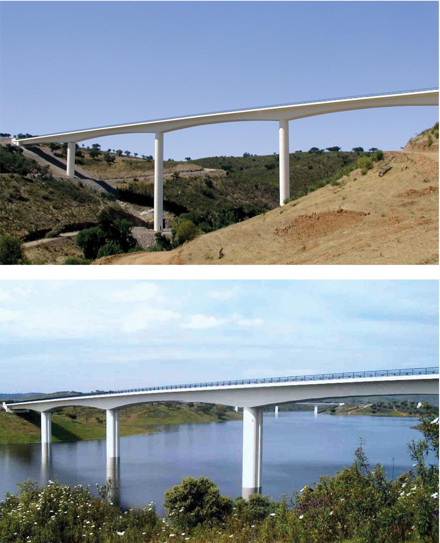
Figure 5.18 The Amieira Bridge over the Alqueva Dam before and after the filling of the dam.
(Source: Courtesy GRID, SA)
If the aim is to place the bridge to be aesthetically detached from the context, complementary colours to the natural ones should be adopted for the bridge; on the other hand, when the idea is to insert (‘hide’) the bridge in the landscape, the dominant natural colour of the landscape, such as the green of the trees or the blue of the sea, should be adopted.
Details play also a relevant role in bridge appearance. Starting from fascia beams, they may be executed with standard colour grey concrete or white concrete when a lighter bridge appearance is sought. In some cases, a steel fascia beam painted in the same colour as the steel bridge deck may contribute to a uniform appearance of the bridge elements. The depth d of the fascia beam should be at least 0.4 m (Figure 5.19) increasing with the height h of the bridge deck. The apparent surface of the fascia beam may be a single plane or made of two planes; different options may also be adopted as shown in Figure 5.19.

Figure 5.19 Details to improve the appearance of the fascia beams.
The dominant direction of the elements in handrails should be horizontal like the dominant direction of the bridge superstructure. The colour of hand railings is quite relevant for bridge appearance. Concrete handrails are rare and should be avoided due to their weight, heavier appearance and difficulty to repair.
Shadow effects induced by slab overhangs in box girder bridge decks may be explored to the benefit of an apparent reduced depth of the bridge deck. The apparent slenderness in box girder bridge decks increases with the shadow effect of the overhangs (Figure 5.20), reducing the apparent depth and by adopting inclined webs as previously discussed. Large overhangs should be adopted in vertical web box girders.

Figure 5.20 Shadow effects induced by slab overhangs in box girder decks.
Details in piers surfaces are quite relevant for the appearance of the bridge. Large dimension concrete pier surfaces should be avoided since a uniform finish of concrete is difficult to achieve.
Details for the concrete pier surfaces, as shown in Figure 5.21 may be adopted as already presented for the bridge design cases in Figures 5.15 and 5.16. The width c and the depth tc, of the transition detail should be sufficient to induce a shadow effect. The inclination 1/i of the detail should be as small possible, but not zero due to the difficulty of taking off the formwork without damaging the concrete finish. Construction joints in pier shafts should include details as shown in Figure 5.21 under the same principle of avoiding large apparent concrete surfaces. The depth of the detail should be sufficient for aesthetics, but small enough to avoid complex detailing of the horizontal steel reinforcement bars. The finish of concrete surfaces in abutments is also relevant for bridge aesthetics, as discussed in Chapter 7.
Figure 5.21 Details in pier shafts to improve the appearance of concrete surfaces.
5.10 Urban Bridges
The design of bridges in urban spaces requires particular attention to aesthetics and environmental issues [9, 10]. The first difficulty is the impact of the bridge in the urban environment, not only concerning aesthetics, but also the impact of the bridge on human life. An urban architect should work with the bridge design team.
Apart from aesthetics, some specific problems concerning the design of urban bridges are as follows:
- The environmental noise impact, very often requiring noise impact barriers, a main issue for bridge aesthetics;
- The execution method to be adopted, very often depending on traffic maintenance requirements during bridge construction or urban occupancy underneath the deck;
- The need to adopt long spans, in some cases due to crossing over roads or railways.
Some bridge design cases are presented next to illustrate these aspects. Figure 5.22 presents the Tagus Suspension Bridge in Lisbon (25th of April Bridge). Approximately 30 years after the bridge and the approach viaduct were built, the railway deck was installed underneath the upper road deck. For the approach viaduct, this required special consideration of:
- noise impact associated with trains rolling on the lower bridge deck;
- an incremental launching scheme to install the steel structure due to the occupancy of the urban space.

Figure 5.22 The Tagus River suspension Bridge in Lisbon after the second phase of construction for the addition of railroad deck at the lower level of the existing truss deck and the northern approach viaduct.
(Source: Courtesy GRID, SA; Photographs by J. Pedro)
For noise impact, it is important to distinguish between structural noise, due to vibration of the superstructure under traffic loads, from aerial noise, due to the propagation of sound waves induced by the trains rolling on the tracks, which could be controlled by noise barriers. For the case under discussion, a ballasted track option on a noise isolation membrane on the top of the deck concrete slab of the superstructure was preferred to a direct fixation track on concrete stringers integrating the deck slab. The preferred option resulted in much higher permanent loads (the ballast represents approximately 30% of the total permanent loads of the deck), but the noise impact was much lower. The only way to reduce structural noise impact in a direct fixation solution was to build a separated concrete slab (30 cm thick) isolated by a noise isolation membrane from the structural slab. The top slab, being independent of the structural slab, could not participate in composite action with the steel structure. This represents an additional permanent load similar to ballast with additional inconvenient for maintenance. An option with an embedded rail (Figure 2.34) was possible to avoid direct fixation and ballast, but due to the length of the viaduct (approximately 1 km long) and special maintenance requirements, the embedded track solution was discarded. The ballasted option was finally retained.
Concerning the execution method, due to urban occupancy underneath the bridge deck, an incremental launched composite steel‐concrete superstructure was the preferred option (Figure 4.112a). The steel superstructure of the viaduct was transported to the site in segments 12–16 m long and erected to two platforms – one located at the north abutment and the other one adjacent to the transition pier with the suspension bridge.
Hence, the superstructure of the viaduct was incrementally launched 600 m from the north abutment in an in‐plan straight alignment and 400 m from the opposite side (the platform at the transition pier) in a constant curved (1000 m radius). The launched operations took about 2 hours each (10 m h−1), after which a new segment was welded at the end sections of the steel structure at the platforms, welding control was made and a new launching operation performed.
Traffic maintenance requirements during construction very often require deck solutions built from precasted concrete girders or steel‐concrete bridge decks. The classical solution with concrete I shape concrete girders is the most commonly adopted, with usually poor results for bridge appearance. The slenderness of the girders is usually low due to the construction phase were the beams have to support the slab deck dead weight cast on the top of the girders and the beams are quite often supported at the piers by cross girders. A much better solution for aesthetics, but more difficult to execute, is to adopt small box girders supported by an embedded cross girder at the piers (Figure 5.23). The concrete slab may be executed on precasted slabs supported by the U prestressed concrete girders. Another option is to adopt small steel box girders, made from U shaped welded sections supported directly on piers that could be installed during the night (Figure 5.24); the deck slab is then cast, as for the previous solution, with concrete precasted U girders. In all these solutions, the end results a multiple box girder, very often far more slender than equivalent solutions made from I girders. The complexity of the construction may be slightly higher, but that is the price to pay for aesthetics.

Figure 5.23 Concrete decks made from precasted U girders. The cross beam is inserted at the pier cross section for aesthetics.
(Source: Courtesy GRID, SA.)

Figure 5.24 Steel concrete composite box girder deck for an urban viaduct over an highway made from U steel girders erected directly over the piers during the night.
Finally, the case of very long spans requiring traffic maintenance in urban viaducts is discussed. Two main issues may be mentioned:
- The erection/execution method
- The slenderness of the superstructure
If main spans in the order of 100 m are under discussion, a prestressed concrete box girder or a steel box girder are usually the preferred options.
For slenderness reasons, aesthetics associated with inclined webs, reduced pier widths and adequacy of execution methods, box girder options are preferred. The main issue with box girders is the need for a sufficient depth at support sections, and minimum free depth (order of 2 m) at span sections. The deck built by a cantilever scheme would require a support cross section depth of at least 5 m, yielding in most cases a negative aesthetic impact at the urban environment. It should be pointed out that, quite often, the deck stands at a low level from the roads below, with a minimum vertical clearance of 5.5 m.
Cable‐stayed solutions or bowstring arches, even for moderate span lengths as usually required in urban environments, may help in improving aesthetics. The first case is illustrated by a cable‐stayed viaduct in Oporto (Figure 5.25a) where a 120 m main span was the required length to overcome several traffic maintenance requirements in the underneath roads and rail tracks. The solution, retained in a bridge design competition, was a cable‐stayed bridge with a single mast and a 120 m main span built by a cantilever scheme from the mast support sections. The deck was a prestressed concrete box girder with steel diagonals (Figure 5.25b), since the staying scheme in the main deck was made with a single plane of stays located along the central pedestrian walkway, 5 m width. A 3D arrangement for the staying scheme was adopted, with two arrangements for the backstays. The mast was designed as an iconic element for the site with the pedestrian walkway passing thought it. The reader is referred to [10] for further details on this urban bridge design.

Figure 5.25 A cable stayed viaduct in Oporto with a main span of 120 m: (a) viaduct as built and (b) deck cross section.
(Source: Courtesy GRID, SA)
References
- 1 Menn, C. (1998). Functional shaping of piers and pylons. Structural Engineering International 8 (4): 249–251.
- 2 Leonhardt, F. (1982). Bridges – Aesthetics and Design, 308 pp. London: The Architectural Press Ltd.
- 3 Strasky, J. (1994). Architecture of Bridges as Developed from the Structural Solution. Proceedings, XII FIP Congress/40th PCI Annual Convention, Washington, D.C.
- 4 Gottemoeller, F. (1988). Bridgescape: The Art of Designing Bridges, 288 pp. Wiley.
- 5 Reis, A. (2010). Two large bridge projects in environmentally constrained areas. In IABSE Symposium Report, 97(17), 61–68. International Association for Bridge and Structural Engineering.
- 6 Melvin, J. (2006). Découvrir l'architecture, 160 pp. Eyrolles.
- 7 Calzón, J.M. (2006). Puentes, estructuras, actitudes, 373 pp. Turner.
- 8 Tzonis, A. and Donadei, R. (2005). Calatrava Bridges, 272 pp. Thames & Hudson.
- 9 Reis, A. (2001). Urban bridges: design, environmental and construction issues. Structural Engineering International 11 (3): 196–201.
- 10 Reis, A., Pereira, A., Pedro, J. and Sousa, D. (1999). Cable‐stayed bridges for urban spaces. In Proceedings of the IABSE Conference on Cable‐Stayed Bridges: Past, Present and Future. International Association for Bridge and Structural Engineering.
- 11 Bennett, D. (1997). The Architecture of Bridge Design, 200 pp. Thomas Telford.
- 12 Billington, D. (2330). The Art of Structural Design: A Swiss Legacy, 211 pp. Yale University Press.