
4
Conceptual Design and Execution Methods
4.1 Concept Design: Introduction
Concept bridge design is an iterative process requiring a comparative analysis of a variety of possible options satisfying a set of data (constraints), namely those related to topographic, geometrical (road or rail alignments), hydraulics, geotechnical, environmental or any other constraints as referred to in Chapter 2. This comparative analysis is usually done at the preliminary design phase. Concept design should take into consideration the objectives of Functionality, Safety and Durability, Economy, Aesthetics and Environmental Integration.
In this chapter, a synthesis of multiple aspects of bridge concept design is presented. Options for the longitudinal and transverse structural systems for the bridge structure are discussed, as well as the choice of structural materials and options for superstructure and substructure. Finally, execution methods and their influence on the concept design is discussed.
The aspect of bridge location, longitudinal and transverse alignments and the elements that should be integrated in the bridge deck were already discussed in Chapter 2. The next step in the design process should be the definition of the main concepts to be taken into consideration in the study of bridge options.
Concepts – This aspect is discussed based taking the bridge case of Figure 4.1. The bridge is located in a deep valley. Piers should be avoided in the central part of the valley due to increased difficulties in execution, height of the piers and aesthetic and environmental integration of the bridge in the landscape. The last aspect is discussed in Chapter 5.
Figure 4.1 Concept design for bridge located in a deep valley: three different options.
The relationship between the height of the piers and the span lengths is a key parameter for bridge options. Taking into consideration the symmetry of the valley, it is preferable to adopt span lengths decreasing from the centre of the valley towards to the abutments. This is a basic concept for integration in the landscape. If one adopts a main span length in the order of 115 m, the adjacent spans could be approximately 77.5 m and the end spans 40 m, as shown in Figure 4.1). With respect to this solution, designated Option A, the following issues may be defined:
- What should be the execution method for the deck considering its height to the ground and the structural material selected?
- What should be the cross section for the bridge deck – an open section (slab‐girder deck) or a closed one (box girder deck)?
- What type of connection should be adopted between the deck and the piers – monolithic or articulated through bridge bearings?
As an alternative to Option A, a bridge deck with continuous multiple spans in the order of 60 m and end spans in the order of 40 m, may be considered (Figure 4.1). This option, Option B, with possible advantages of a reduced cost for the deck should be executed through a method different from option A. Of course, option B has some disadvantages with respect to option A concerning aesthetics and landscape integration. With respect to option B, the following issues may be stated:
- Based on the span lengths should a bridge deck with prefabricated girders in steel or in prestressed concrete, that could be launched from the abutments, or a cast in place prestressed concrete (PC) deck, that could be executed by a moving scaffolding supported by the piers,
- For the case of launched steel girders, what should be the number of steel girders at the cross sections?
- For the case of precasted PC girders, what should be the number of girders at the cross sections in order to be compatible with the launching capacity of the equipment? Should the span length be reduced for this case in order to reduce the dead weight of the girders?
- In both options – steel and concrete, should the slab deck be in RC or in PC, casted using the girders as scaffolding?
In principle, for this option B if a concrete deck is adopted it would be preferable to reduce the span length to a value between 40 and 45 m for the benefit of the cost of the launching or moving scaffolding equipment that are very much conditioned by the deck self‐weight.
As an alternative to options A and B, a different Option C consisting of an arch bridge (Figure 4.1), or a frame bridge with inclined legs (Figure 1.8) may be considered. Of course, from a landscape integration point of view, these types of solutions would be preferable. However, these bridge typologies may raise the following issues:
- Are the geotechnical conditions at the slopes sufficiently good enough to absorb high horizontal component reactions (impulse H in Figure 4.1) from the arch?
- How can the arch be executed from the slopes assuming scaffolding supported from the ground is not feasible due to its high cost?
These issues show the interaction between selection of a bridge option and execution methods. No concept design should be made without going through the method to be adopted for the execution.
4.2 Span Distribution and Deck Continuity
4.2.1 Span Layout
As previously discussed, the most current longitudinal structural systems are a continuous girder bridge or a multiple span frame bridge. Span distribution is a basic issue that cannot be defined independently of the execution method.
Starting from the approximate location of the abutments that should be made in order to reduce its height, the total length of the superstructure is defined. Consideration must be made for a minimum clearance in the order of 2 m should retained between the underneath of the deck and the ground in order to protect the bearings at the abutments from any vandalism acts, particularly on urban bridges, and accumulation of litter as well. In bridges located in flat areas without any particular requirement for a main span, such as crossing a river, a navigation channel or a motorway, approximately equal inner spans should be the most adequate solution for a continuous girder bridge. The end spans should be in the order of 0.6–0.8 of the typical span lengths (Figure 4.1). This span arrangement contributes to a better distribution of permanent bending moments at the end spans and to avoid any uplift at the bearings located at the abutments. Of course, increasing span lengths would increase the cost of the superstructure and reduce the cost of the substructure. However, the former may represent 60–80% of the total bridge cost. The cost of piers and foundations may represent 20–40% of the total bridge cost, depending on the geotechnical conditions. The piers themselves usually do not represent more than approximately 10% of the total cost. The cost of deep foundations, by piles, may significantly increase the cost of the substructure. The same happens when piers are located in water or alluvium zones were the cost of execution of the pile caps is quite significant. Cofferdams are usually required for piers located in rivers and this condition may justify increasing the span length of the superstructure. The balance between the cost of superstructure and substructure should be a main issue for the conceptual design of the bridge.
If the bridge is located in a deep valley, a span modelling decreasing from the centre towards the abutments is the best solution as referred to in Section 4.1. However, assuming, for example, a cast in place girder deck, the variation of spans introduces an increased difficulty in construction. The depth of the superstructure should vary as shown in Figure 4.1 for Option A. The prestressing layout and the formwork should be different at each span. In Option B of Figure 4.1 the typical prestressing layout may be the same for most of the internal spans.
4.2.2 Deck Continuity and Expansion Joints
Decks should be continuous as far as possible to avoid internal expansion joints that are costly to maintain and very often need to be replaced more than once during the life of a structure. If possible, one should adopt only one expansion joint at each end span at the abutment‐deck connections. The limits for continuity of the decks are of course the displacements to be accommodated at the expansion joints. For example, for a PC bridge with a total continuous deck in the order of 700 m, as in the bridge case of Figure 4.2 (Freixo Bridge, in Oporto), the deck is monolithic with the adjacent piers to the main span (150 m long) and supported by bearings at all the other piers. However, pier P4 has fixed bearings, while all the others have sliding unidirectional bearings. At the abutments, unidirectional bearings are introduced, as well as seismic dampers (a subject discussed in Section 7.4) to allow slow movements due to temperature, shrinkage and creep effects; high frequency movements due to earthquakes are restricted by the seismic dampers. The centre of stiffness of the piers (Section 7.2.2) is approximately located at the centre of the main span. The maximum distance from the centre of stiffness to the south abutment (Gaia) is approximately 400 m. Shrinkage, creep and thermal variations, induce amplitudes of movements at the south expansion joint equivalent to a thermal variation in the order of +15°/−60°C resulting in a movement in the order of 300 mm. With a safety coefficient of at least 1.2–1.3, this means the expansion joint should be designed for approximately 400 mm of amplitude. A large part of this movement is due to shrinkage and creep effects inducing a shortening of the deck. When the expansion joint is installed, a preset should be specified taking into consideration the structure temperature at time of joint installation.

Figure 4.2 The Freixo Bridge in Oporto (150 m main span).
(Source: Courtesy GRID, SA)
When the continuity of the deck is too large, the expansion joints need to accommodate very large amplitude displacements and are too costly. As an order of magnitude, continuous bridge lengths of 600–700 m nowadays (although in some cases the continuity may reach 1000 m or even more, as in Millau road Viaduct in France: see Figure 4.33 later) have a multi‐cable‐stayed steel deck of 2460 m, or in the HSR (High Speed Railway) Viaduct de las Piedras in Spain, having a steel‐concrete composite deck of 1209 m or in the Bridge over Guadiana in Alqueva (Figure 5.8), a PC box girder deck with a span of 1230 m. That depends, as well, where the centre of stiffness of the top of the piers is located. It should also be noted that when an internal expansion joint is adopted at specific section on a pier, one has movements coming from both parts of the deck adjacent to the expansion joint. This may double the movement to be accommodated at the expansion joint. In this case, the continuity of the deck may need to be reduced. The referred value for continuity of 600–700 m may be reduced to 300–350 m unless the expansion joint is designed for larger movements. Another aspect of deck continuity is the displacements that should be accommodated at the sliding bearings on the piers. The top sliding plates at the bearings (see Section 7.3) should be large enough to accommodate the movements of the superstructure.
One may designate the distance from the centre of stiffness to the expansion joint location as the dilatation length. In railway bridges, an additional problem exists related to the rail‐structure interaction. The continuity of continuous welded rails on ballast integrated on the slab deck requires long dilatation lengths, the adoption of rail expansion joints. Otherwise, the stresses induced in the rail due to differential movements of the superstructure with respect to the rail may be too large. The reader is referred to specific literature [1] on this subject.
4.3 The Influence of the Execution Method
To illustrate the influence of the construction method on the design of a bridge structure, two examples are considered:
- A concrete bridge built by the balanced cantilever method;
- A composite bridge with the slab deck cast in place on the previously erected steel girders.
4.3.1 A Prestressed Concrete Box Girder Deck
For the first example, a three span bridge, the evolution of the static system is shown in Figure 4.3. In Figure 4.4 a design case illustrates this construction scheme. The bridge deck is executed in symmetrical segments from the two piers with segment lengths between 2.5 and 5.0 m in length. For that there is a pair of moving scaffoldings from each pier in a balanced cantilever scheme. Reaching nearby the mid‐span, the end sections of two cantilevers are connected through a closure segment with a length in the order of 2–3 m generally. At the end spans, the deck length to connect the end section of the cantilever with the support section at the abutments is cast on scaffolding supported from the ground. The internal forces at the execution phases are determined based on a simple cantilever. The negative bending moments during the execution phases of the deck increase towards the support section at the pier where the deck is built in.

Figure 4.3 Evolution of the static system in a bridge built by balanced cantilever.

Figure 4.4 The bridge over the Ribeira Funda, Madeira Island, built by balanced cantilever (135 m main span) – Approaching the execution of the closure segment at mid‐span.
(Source: Courtesy GRID, SA)
The shape of the bending moment diagram requires an increased depth, with a parabolic variation, towards the support section. These negative bending moments control the required depth of the section at the supports, and the overall geometry of the deck cross section. Thus, a thick lower flange is required to accommodate high compressive stresses that are developed during the execution phases. The ideal cross section is a box with increased thickness of the lower flange towards the support section. In a second phase, after completing the balanced cantilever scheme, the deck lengths at the end spans are cast on formwork supported from the ground as shown in Figure 4.3. In a phase 3, the closure segment at mid‐span is cast. If behaviour was elastic, the bending moments at the closure mid‐span section would remain zero. However, due to creep effects of the concrete, the bending moments in the deck tend to approach the bending moment diagram of a continuous girder deck with three spans as if it was cast in a single phase on formwork supported from the ground and the formwork was also removed in a single phase. Therefore, at the mid‐span, a positive bending moment exists after the closure segment is cast. The bending moment diagram is time dependent but it also tends in the long term towards the bending moment diagram of a continuous deck.
4.3.2 A Steel‐Concrete Composite Steel Deck
In the second example, a steel‐concrete composite deck is shown in Figure 4.5. After the erection of the steel girders, erected, for example, by cranes from the ground, the slab deck is cast using the girders as scaffolding. The stresses on the steel girders due to the dead weight of the concrete are evaluated as if the structure was a steel‐only structure. However, after hardening of the concrete, the composite steel‐concrete action is developed and for all the remaining loads, like superimposed dead loads and live loads (traffic loads), the stresses are evaluated for a steel‐concrete composite section. The cross section dimensions of the steel girders should be established taking due account of the execution phases.


Figure 4.5 A composite steel‐concrete deck for an Oporto Metro viaduct (total length 498.2 m with a main span of 48.5 m).
(Source: Courtesy GRID, SA)
4.3.3 Concept Design and Execution: Preliminary Conclusions
From these examples, some conclusions can be drawn:
- The evolution of the static system during construction should be taken into account for the design of the bridge structure;
- The geometry of the final structure and the longitudinal and transverse models can only be established taking into consideration the execution method.
In next sections, the most common typologies for the superstructure of concrete, steel and composite bridges are discussed and typical pre‐design rules are referred to.
4.4 Superstructure: Concrete Bridges
4.4.1 Options for the Bridge Deck
For the conceptual design of the superstructure, options should be taken with respect to: (i) the structural materials, (ii) the longitudinal structural system, (iii) the transverse cross section of the deck, (iv) the connection between the deck and the piers and abutments and (v) the execution method. Several of these options were considered in previous sections and chapters. In this section, a detailed discussion is presented for the design of deck cross sections, considering concrete as the structural material for the deck. The option for the transverse deck cross section depends on:
- The width of the deck (b);
- The span length (l);
- The slenderness (l/h) envisaged for the bridge deck with a depth (h);
- The execution method and construction equipment to be adopted.
The following options may usually be considered for a concrete deck, in RC or PC:
- Slab and voided slab decks
- Ribbed slab and slab‐girder decks
- Box girder decks
These options (Figure 4.6) may be adopted for the cross section of bridges with different longitudinal structural systems, namely simply supported or continuous beam bridges, frame bridges, arches or even for cable‐stayed bridges.

Figure 4.6 Equivalent depth of the deck (heq).
One way of comparing different cross sections options, as shown in Figure 4.6, is to compare the so called equivalent depth of the deck, given by:
where A is the area of the deck cross section of width b. Hence, heq is the depth of a rectangular solid slab with the same weight. The upper and lower stresses at the extreme fibres of the cross section deck (at distances vi and vs to the centroid) under bending, depend on the section module I/vi and I/vs where I is the relevant moment of inertia. The ideal most efficient cross section of area A, to resist to a bending moment is made of two separate thin layers (flanges) each of area A/2, at a distance h. The moment of inertia of this ideal section is approximately I = A i2 where i = h/2 is the radius of gyration with respect to the neutral axis. The efficiency of a cross section depends how much vi and vs differ from the i value of the actual cross section. Taking the ratios i/vi and i/vs an efficiency parameter, ρ, may be adopted for comparing different cross section options:

The ideal cross section has ρ = 1; for a real deck cross section ρ < 1. Different deck cross sections are discussed and compared in the next sections, with respect to efficiency. Of course, the efficiency of a deck cross section cannot be measured only by its heq and ρ values. Labour costs come into play, namely concreting rate, formwork and placing of the ordinary and active (prestressing) reinforcement. First, the concrete material should be considered.
4.4.2 The Concrete Material – Main Proprieties
4.4.2.1 Concrete
The compressive strength of concrete is denoted by concrete strength classes that relate to the characteristic (5%) cylinder strength fck at 28 days (or the cube strength fck,cube) in accordance with EN 206‐1 [2]. The strength classes for concretes frequently used in bridges are presented in Table 4.1.
Table 4.1 Main proprieties for concrete frequently used in bridges.
| Strength class for concrete | C25/30 | C30/37 | C35/45 | C40/50 | C45/55 | C50/60 |
| Characteristic compressive strength fck (MPa) | 25 | 30 | 35 | 40 | 45 | 50 |
| Mean compressive strength fcm = fck + 8 (MPa) | 33 | 38 | 43 | 48 | 53 | 58 |
| Mean tensile strength fctm (MPa) | 2.6 | 2.9 | 3.2 | 3.5 | 3.8 | 4.1 |
| Secant modulus of elasticity Ecm (GPa) | 31 | 33 | 34 | 35 | 36 | 37 |
| Strain at peak stress εc1 (‰) | 2.1 | 2.2 | 2.25 | 2.3 | 2.4 | 2.45 |
The mean tensile strength fctm refers to the highest stress reached under concentric tensile loading. The flexural tensile strength can be increased for members with depths h up to 0.6 m, by using the relationship: fctm,fl = max {(1.6 – h) fctm; fctm}.
The elastic deformations of concrete largely depend on its composition (especially the aggregates). Therefore, values for the secant modulus of elasticity Ecm, between σc = 0 and 0.4 fcm, given in Table 4.1 for concretes with quartzite aggregates, should be regarded as indicative and specifically assessed if the structure is likely to be sensitive to deformations. For limestone and sandstone aggregates, the values should be reduced by 10 and 30%, respectively. For basalt aggregates, the values should be increased by 20%. Poisson's ratio may be taken equal to 0.2 for uncracked concrete and 0 for cracked concrete. The linear coefficient of thermal expansion is usually taken equal to 10−5 C−1. The value of the design compressive is defined from these values as fcd = fck/γc, where γc is the partial safety factor for concrete, usually 1.50.
Finally, for executing the structural analysing and computing the resistance of concrete cross sections under compression the stress–strain diagrams of Figure 4.7a and b may be respectively adopted, using the properties from Table 4.1.


Figure 4.7 Stress–strain diagrams for concrete, reinforcing and prestressing steel.
4.4.2.2 Reinforcing Steel
Reinforcing steel can take the form of bars, de‐coiled rods or welded fabric. Figure 4.7c presents the typical stress–strain diagram for reinforcing hot rolled steel (dashed) with the characteristic yield strength fyk and tensile strength ftk, and the correspondent strain, εsu. The same figure also includes the stress–strain diagram usually used for design (for tension and compression), with a yield strength fyd = fyk/γs and γs = 1.15, the partial safety factor for reinforcing steel at ULS (Ultimate Limit State).
The design value of the modulus of elasticity Es is assumed to be 200 GPa. Typical values of strains εs1 and εud are, respectively, 2.174‰ and 10‰ for reinforcing steel B500 (in accordance with the EN 10080), the most frequently used in bridges.
4.4.2.3 Prestressing Steel
Prestressing steel usually appears in concrete decks as wires, bars or strands, with low level of relaxation (class 2) and susceptibility to corrosion. Additionally, prestressing steel should be adequately and permanently protected against corrosion in sheaths or ducts. These ducts are grouted with cement grout (both bonded and external tendons), with petroleum wax or mineral‐oil‐based grease (for external unbounded tendons only).
Figure 4.7d presents the typical stress–strain diagram for prestressing steel (dashed) with the characteristic 0.1% proof stress fp0.1k and tensile strength fpk and the correspondent strain, εuk. The properties of prestressing steels are given for example in EN 10138. The same figure includes also the stress–strain diagram usually used for design, with a strength fpd = fp0.1k/γs, with γs = 1.15 at ULS.
The most commonly prestressing steel used in concrete bridges consists of a bundle of seven‐wire strands, 15.3 or 15.7 mm nominal diameter (designated T15 normal or T15 super), with nominal tensile strengths of 1770 or 1860 MPa, respectively.
The design value for the modulus of elasticity Ep may be assumed equal to 195 GPa for strands, although the actual value can range from 185 to 205 GPa, depending on the manufacturing process. Typical values of strains εs1 = 0.75‰, εud = 10‰ and proof stress fp0.1k = 0.9 fpk = 1680 MPa for the prestressing steel Y1860 (in accordance with the EN 10138‐3 [3]).
The maximum forces in each strand should be obtained with the stressing limit at tension stage fpo = min {0.8 fpk; 0.9 fp0.1k}. Bars have usually lower stress limits due to higher susceptibility to fatigue and brittle failure.
4.4.3 Slab and Voided Slab Decks
Slab bridge decks (Figure 4.8a) with rectangular shapes or with overhangs may be adopted for spans up to 30 m. For small isostatic spans, say up to 20 m, RC‐reinforced concrete may be adopted. Increasing spans generally require the use of PC‐prestressed concrete. If the plan geometry is complex, namely in skew slab or curved bridge decks, the solid rectangular slabs have the advantage of simplicity of execution – formwork, reinforcement, concreting and installation of prestressing cables. The main disadvantages are the large dead weight and small eccentricities for prestressing cables, generally requiring large quantities of concrete, steel reinforcement and prestressing. Typical values for pre‐design areas are as follows:
- Slab depth h – 0.25–0.80 m;
- Spans l – up to 15–20 m in RC and 20–30 m in PC;
- Slenderness – l/h = 15–25 in RC and 15–35 in PC.


Figure 4.8 Different options for concrete bridge decks.
Some of the disadvantages pointed out for slab decks may be overcomed by the adoption of a voided slab deck as shown in Figure 4.8a. The voids are usually circular or rectangular tubes in polyvinyl chloride (PVC), expanded polystyrene, thin spiral steel tubes or even in wood formwork. Some minimum distances, as indicated in Figure 4.9, should be respected in locating the tubes. Rectangular tubes may yield a reduced dead weight for the cross section, but have the disadvantage of difficulty for concreting underneath the tubes. In this case, the maximum width of the tubes should not exceed 1.0 m. When prestressing cables are adopted, the minimum distance of voids should be at least three times the diameter of the ducts. Special care should be taken to avoid tubes floating during concreting due to upward forces induced by concrete before hardening. For a void with a diameter Ф the upward force is (Фγc) where γc is the unit weight of concrete. For example, a void of 0.7 m diameter has an upward force of approximately 10 kN m−1. Because of that it is convenient to fix the tubes by specific reinforcement bars to the underneath layer of the main reinforcement. Care should also be taken to prevent water entering the voids during concreting. The voids may be interrupted at some transverse cross sections, in particular when large voids are adopted with respect to the total cross section. These cross beams (Figure 4.9) avoid any distortional effects at the cross sections. Over the piers, the voids are necessarily interrupted in order to transfer the bearing reaction, as in Figure 4.10.

Figure 4.9 Voided slab decks: minimum distances for location and void dimensions.

Figure 4.10 A design example of a continuous voided slab deck with single piers: overpass at the Funchal – Airport Highway, Madeira Island, Portugal.
(Source: Courtesy GRID, SA)
The main advantages of the voided slab decks, with respect to a solid slab, are the reduced self‐weight (reduced heq) and the increased depth h, allowing an increased eccentricity for prestressing cables and even for the ordinary reinforcement. The ρ factor of a voided slab is larger than in a solid slab of the same self‐weight, that is, with the same heq. The main disadvantages of a voided slab with respect to a solid slab deck are an increased difficulty for the execution in particular for curved plane geometries.
In Figure 4.11 a comparison is made of the efficiency parameter ρ (Eq. 4.2) for different deck cross sections. Solid and voided slabs have a ρ in the order of 0.3–0.4 that may be compared to a box girder deck where ρ values are usually between 0.5 and 0.7.

Figure 4.11 Efficiency parameter for different concrete deck cross sections.
4.4.4 Ribbed Slab and Slab‐Girder Decks
To increase the efficiency of a slab deck under increasing spans, say above 30 m, it is necessary to reduce the self‐weight of the cross section (A γc, kN m−2) and to increase the eccentricity of the prestressing cables. This can be achieved by transforming solid slab or voided slab sections in a ribbed slab section or in a slab girder deck (Figure 4.8b). The difference between these two options is the width of ribs. When the ribs are narrow, depth may be increased keeping the same heq, resulting in a slab girder deck. In a ribbed slab deck, the number of ribs depends on the width, b, of the deck. To keep the slab deck in RC in the transverse direction, this requires limiting the transverse free span between ribs to about 5–6 m. With two ribs of 2–3 m width (at the slab deck level) and overhangs (transverse cantilevers of the slab deck) in the order of 2 m, a total deck width of 14–15 m may be reached. The number of ribs may be increased to three or even four in the limit if the deck width is very large. This type of deck option, in PC, may reach span lengths up to 35 m with constant deck height. Spans up to 40 m may be reached with a variable height depth, for example, in a three‐span continuous deck. The ribbed slab option in PC is a more efficient solution than a voided slab deck for the same span length. The ρ values may reach 0.35–0.40.
Typical values for pre‐design of a ribbed slab deck are as follows:
- Spans l – up to 35 m in PC
- Slab deck thickness (between ribs) – 0.22–0.30 m
- Width of the ribs at the slab deck level – 1.5–3.0 m
- Slenderness – l/h = 20–35 in PC.
The lower slenderness values are usually adopted for simply supported spans. Ribbed slab decks are a quite convenient option for overpasses on highways where continuous three‐span decks may require a central span up to 35 m, avoiding any pier in the central strip of the highway.
A combination of two schemes, rib and voided slabs, is an option in particular for increasing span lengths and width of the deck, as shown in the example of Figure 4.12.

Figure 4.12 A two rib voided slab deck for a continuous prestressed concrete curved viaduct in a highway in Funchal, with typical spans of 30 m.
For medium spans, say 40–70 m, constant depth or variable depth slab girder bridges in PC are needed, unless box girder sections are adopted (Figure 4.8c). The slab girder deck may be adopted with two girders only and a RC slab deck (Figure 4.13). That is, in general, the more economic option. The main girders are located at 4–8 m in general if the slab deck is in RC. Multiple girder bridge decks, with three or four main girders, are only justified for large deck widths or very limited vertical clearances. If the depth h of the deck should be limited due to clearances or aesthetical reasons, yielding a slenderness l/h above 17 (constant depth cross sections) box girder options are usually preferred.

Figure 4.13 Slab‐girder deck cross sections – with two or four girders.
In slab‐girder decks, the slab deck may be prestressed in the transverse direction to keep the deck with two girders only. The free transverse span length between girders, may reach values as high as 15 m, or even more, for very wide highway decks up to 30 m (Figure 4.14). Large span overhangs and a variable thick slab deck are required, in these cases, to reduce transverse prestressing. The slenderness of the main girders (l/h) may also be reduced to values as low as 12–15 in constant depth decks, with only two girders and very wide decks.

Figure 4.14 Deck cross section with only two girders for a very wide deck (Vorland Bridge, Germany, 1968; main span 39 m, deck slenderness of 13).
(Source: Adapted from Ref. [4])
Cross beams between the main girders (Figure 4.15) have been a solution very much adopted in the past. Nowadays, to simplify execution, namely when formwork launching girders are adopted (see Section 4.6). It is possible to achieve the transverse load distribution (Chapters 3 and 6) between main girders by the slab only. Even in very wide decks, like the one in Figure 4.14, the transverse load distribution may be made by the slab only for easiness of the execution scheme. If span cross beams are adopted, for example, when the deck is concreted on a formwork supported from the ground, its number should be limited to one at each mid‐span or two cross beams at one‐ and two‐thirds of the intermediate spans and one cross beam at 0.4 of the side spans (Figure 4.15). The cross and main girders work as a grid structural system. It should be noted that at the end sections of the side spans (i.e. at the abutment sections) a cross beam is usually adopted to support the slab deck. Otherwise, the slab deck has a free edge and the transverse bending moments due to local traffic loads are very high. These end cross girders are the support for the expansion joints as well. At intermediate support sections, it is also convenient to adopt cross girders, transferring pier reactions to the superstructure and helping to distribute horizontal transverse loads when two pier shafts are adopted at support sections. The intermediate cross girders may also have the function of accommodating bridge bearings in the case of a single pier shaft with a reduced width and no pier cap. The main girders work as T beams in positive bending moment regions – sagging moments. In negative (hogging) bending moment regions, the slab deck is considered to be cracked at least at ULS and the section works as a rectangular cross section.

Figure 4.15 Longitudinal and transverse cross sections of a slab‐girder deck with cross beams.
In most cases, at intermediate piers of slab‐girder decks, the deck is supported by bearings. The cross girders may also work in frame action with two pier shafts, that are monolithically connected to each girder. However, this is not so common due to greater execution difficulties and induced longitudinal bending moments in the piers.
When the span increases, the negative bending moments at pier sections are not easy to accommodate because the negative bending compressive stresses in concrete tend to be too high. These negative bending moments of permanent loads are reduced by the prestressing effects (positive primary bending moments) but negative hyperstatic (secondary) bending moments are developed in continuous girder decks reducing the beneficial effect of the prestressing. Traffic loads and negative thermal gradients also induce compressive stresses at the bottom of the main girders. To reduce the compressive stresses at the bottom of the main girders, there are the following options:
- To increase the depth of the main girders
- To increase the width of the main girders
- To adopt a compressive flange at support sections
- To adopt a compressive reinforcement at the bottom of the girder (Figure 4.16a)
- To introduce a wide cross beam between main girders at support sections (Figure 4.16b)

Figure 4.16 Different options for reducing compressive stresses at the bottom fibres of a slab‐girder deck.
The first option is the most efficient, although a compressive flange is a structurally very good solution, but difficult to execute with risks of not reaching at the bottom flange a well compacted concrete. If this option is adopted it is recommended to leave some openings at the formwork of the bottom flange to have an easy access for vibration of concrete.
The slab deck may be prestressed transversally, at least for decks with two girders only and widths above 10–12 m (Figure 4.17). This allows adopting slender slab decks, threby reducing self‐weight. The transverse prestressing should be made by cables with a reduced number of strands (usually three or four strands per cable) and close spacing (0.5–1.0 m). It improves the behaviour at serviceability limit states (SLS), namely cracking effects that may be avoided under frequent or even characteristic load combinations in the case of severely aggressive environments.
Figure 4.17 Transverse prestressing in the slab‐girder decks of Figure 4.20.
A main aspect for the concept design of slab‐girder decks is the location of the main girders at the cross section. The main rule is to avoid torsion effects in the main girders under permanent actions (dead loads – self‐weight, walkway, fascia beam, handrail and transverse prestressing). The transverse bending moment coming from the slab cantilever should be balanced by the transverse bending moment from the slab between girders (Figure 4.18). In a slab‐girder deck, the cantilever span length should be between 0.3 and 0.5 of the distance between main girders. If the deck has two girders only, the resultant force from the dead loads (transverse prestressing included) of the half deck (Figure 4.17), should pass through the centre of gravity of each girder. The condition of zero torsion moment at each girder under permanent action is of course a target and very often one needs to accept some moderate permanent torsion in the main girders. When the transverse bending moments, to the ‘left and right’ of the main girders, are fully balanced, the slab does not rotate at the slab‐girder connection, which means the slab between girders may be considered for dead loads, as built in along both longitudinal edges.
Figure 4.18 Location of the main girders in slab‐girder decks to avoid permanent torsion in the girders.
The transverse cantilevers should be designed with variable thickness with a minimum of 0.15–0.20 m at the free edge. It is quite important to take into account the plate anchorage dimensions for transverse prestressing if it exists. A design example is shown in Figure 4.19 for the deck of a cable‐stayed bridge where the transverse cantilevers of the slab deck (overhangs) reach 5.5 m.

Figure 4.19 A voided slab deck in the approach spans of a cable stayed bridge (over river Lis, in Leiria, Portugal) with an axial scheme for the stay cables. Transverse prestressing of the slab deck with long (5.50 m length) overhangs.
(Source: Courtesy GRID, SA).
The slenderness of the girders, defined for continuous spans as l/h, should be reduced for simply supported spans li/h to values in the order of 70%, that is, li/h = 0.7 l/h. In the following, some indicative values for pre‐design are given for RC and PC decks.
Due to execution constraints, to be discussed in Section 4.6, most slab‐girder decks have a constant depth, particularly if they are built adopting a formwork launching girder. However, if they are cast on fixed scaffolding supported from the ground (classical scaffolding or stationary falsework) a variable depth girder may be a good option from both the aesthetics and structural points of view. Table 4.2 present indicative values of slenderness l/h, the lowest values may be adopted for support sections while the highest values are usually adopted for mid‐span sections. A parabolic variation of the girder depth or a linearly variable depth from the support section to one‐fifth or a quarter of the span may be also adopted, keeping a constant depth in the central parts of the spans. These variations in girder depth have a positive impact in reducing the quantity of longitudinal prestressing.
Table 4.2 Slenderness for reinforced and prestressed concrete continuous girder decks.
| Deck cross section | Slenderness | RC deck | PC deck |

|
|||
| l/h | 12–17 | 14–25 | |

|
|||
| l/h | 14–20 | 17–34 |
Another relevant aspect is the required width of the girders to accommodate the prestressing cables, particularly at sections where continuity anchorages are located. This may be concluded from minimum free clearances for the anchor plates if they are located side by side. Even for small 12‐strand cables, a minimum width of 0.7 m width should be considered. If the continuity anchorages are not side by side, the width of the girder may be reduced to a minimum of 0.4–0.5 m. A minimum value of 0.6 m is recommended for installation of prestressing cables and to increase the concreting rate and good vibration conditions of the concrete. It is also convenient, for easiness of removing the formwork, to design the girders cross section slightly tapered to the bottom as shown for the design case in Figure 4.20.

Figure 4.20 Design example of a slab‐girder deck. Approach spans of the bridge over Sorraia River in the highway A13 in Portugal (typical spans of 43.7 m).
(Source: Courtesy GRID, SA).
Typical values for pre‐design of a slab‐girder deck are as follows:
- Spans l – up to 70 m in PC
- Slab deck thickness (between girders) – 0.22–0.30 m to 0.40–0.50 m at the connection with the girders
- Width of the girders at the slab deck level – 0.5–0.9 m
- Slenderness – l/h = 15–20 in PC.
4.4.5 Precasted Slab‐Girder Decks
Main girders of a slab‐girder deck may be precasted as shown in Figure 4.21. The number of girders to be adopted at cross sections should be studied with respect to the function of the self‐weight of each girder and capacity of erection equipment, namely cranes or launching girders, as discussed in Section 4.6. The distance between axes of precasted girders usually varies between 2.5 and 5.0 m. The slenderness of the girders may vary between 1/15 and 1/20 of the span lengths. The slab deck, usually made in RC, is cast on top of a classical formwork, suspended from the girders or on top of a precasted panel. These panels may be fibre reinforced cement for small distance between girders or precasted RC panels in composite action (participating precasted panels) with the concrete cast in situ of the slab deck for large spacing of the precasted girders. The precasted girders may be pre‐ or post‐tensioned. The geometry of precasted girders is currently an I shape with a wide top flange and a narrow lower flange, as shown in Figure 4.22. The lower flange accommodates the pretension wires or the post‐tensioned prestressing cables. The web should have sufficient width for shear forces but particularly to allow for the prestressing cables to “go up” in the webs of continuous decks. If a prestressing cable needs to ‘go up’ in the web, the minimum web width is three times the diameter of the duct. For example, for a 12‐strand 15 mm prestressing cable, this would require a minimum width of about 0.27 m for the web. The next solution to obtain lighter prestressed girders is to increase the width of the web when approaching the end sections. In this case, the prestressing cable should go up only at the wider web sections. In any case, minimum widths of 0.2 m are recommended for easiness of installing the ordinary reinforcement and keeping minimum covers for durability. Compacting the concrete is very often made by adopting vibrators attached to the formwork. The lower flange of precasted girders is subjected to high compressive stresses, and its geometry and class of concrete should be studied in conformity.

Figure 4.21 Slab‐girder deck with prestressed precasted girders.

Figure 4.22 Typical geometry of a precasted girder for a bridge deck, with the slab concreted on precasted concrete panels.
The reader is referred to specific literature on precasted girder decks [5], but a main subject should also be discussed here: the option of simply supported multiple span decks or continuous spans decks, as shown in the schemes of Figure 4.23. The former are easy to erect but have a multiplicity of disadvantages, namely requiring twice the number of bearings and expansion joints at each support section usually requiring frequent maintenance. Besides, the simply supported independent girders are usually less slender and if they are supported by cross beams or pier caps with large disadvantages for the appearance. The best solution, both aesthetically and structurally is to adopt a continuous deck. The girders and the slab are continuous at the support sections, achieved by concreting a transverse cross beam at each support section. A second phase of prestressing is required for reaching full continuity of the deck. This solution proved to yield the most aesthetically pleasant solutions, increasing the life span of the bridge and yielding improved comfort for the users. Of course, the continuous solution is more difficult to execute and more expansive. An intermediate solution is to make continuity by the slab only. The girders tend to work as simply supported and the slab needs to have sufficient ordinary reinforcement to accommodate tensile stresses and to control cracking effects, induced by the traffic, differential thermal gradients and time‐dependent effects of the concrete. Being an attractive solution from an execution point of view, the partial continuity by slab only has the same aesthetical inconvenience as the simply supported independent span option.

Figure 4.23 Different schemes for slab‐precasted girder decks at support sections: (a) independent simply supported spans; (b) partial continuity through the slab deck and (c) full continuity through the cross beams.
4.4.6 Box Girder Decks
For long spans, the compressive stresses at the lower flange of slab‐girder decks tend to reach very high values. In a box section, a complete lower flange to accommodate these stresses exists (Figure 4.8c). Besides, in curved bridges where torsion effects are usually relevant, box sections have a large torsion rigidity and high capacity to resist to shear torsion stresses. Other cases, where box girder decks are the most convenient option, are bridge cases where a reduced depth is required for vertical clearances or aesthetical reasons, such as in urban viaducts or bridges over navigation channels.
Box girder sections, single or multiple‐cell as shown on Figure 4.24, offer the following advantages with respect to a slab girder deck:
- a large compressive lower flange allowing compressive stresses at support sections under negative bending moments;
- a large torsional resistance in uniform torsion and reduced stresses due to warping torsion (Chapter 6), which is very convenient for curved bridges;
- for the same self‐weight of a slab‐girder deck (same heq) an increased slenderness (l/h) in the order of 20%;
- larger eccentricities for the prestressing cables at support sections subjected to negative bending moments;
- small creep deformations since the permanent compressive stresses are smaller than in an equivalent slab‐girder deck.

Figure 4.24 Single cell and multi‐cell box girder decks.
The most relevant disadvantage of box girder options with respect to slab‐girder decks is an increased difficulty in execution, namely for concreting, formwork and installation of prestressing cables and ordinary reinforcement.
Box girder sections are the preferred options for long span bridges, namely for spans above 70 m and up to 200 m. Above this value or even less, say 150 m, cable‐stayed bridges may be competitive and certainly more pleasant from an aesthetic point of view.
Nowadays, single cell box girders are preferred to multi‐cell box sections, even for wide bridges. The use of transverse prestressing, the adoption of transverse ribs or even inclined struts (concrete or steel tubes) (Figure 4.25) may allow the adoption of box girder sections for deck widths with more than 20 m. Only for very limited depths, due to clearance restraints, multi‐cell box girders are preferred. Even so, in these cases, it may be possible to adopt two box girder sections, independent or interconnected, through the deck slab.

Figure 4.25 Box girder decks with transverse ribs or inclined struts for wide decks.
Box sections in continuous spans have usually a variable thickness lower flange, with a minimum of 0.2 m at the mid‐span and a thickness at support sections sufficient to accommodate the compressive stresses, while also controlling creep effects. For long spans built by the cantilever method, the thickness of the lower flange at the support is in the order of l/100, where l is the span length, but clearly this depends on the width of the lower flange. This thickness is reduced towards the mid‐span in a continuous fashion along a certain length.
Typical slenderness values for box girders are indicated in the following table:
| Constant depth box girders | (l/h) = 18–25 for continuous spans (l/h) = 17–21 for simple supported spans |
| Variable depth box girders | (l/h) support = 15–20 (l/h) mid span = 30–45 |
To facilitate execution, a minimum depth of 2.0 m (better 2.2 m) is recommended at mid‐span sections; otherwise access along the span length, very much required during construction, is more difficult.
The overhangs of the slab deck (transverse cantilevers) have a length, b1, that is very much dependent on the distance, b2, between webs. Of course, b1 depends very much on the negative transverse bending moments induced by truck loading and width of the walkways. The relationship b1/b2 is in the order of 0.4–0.5, to reduce permanent transverse bending moments in the webs (Figure 4.26) and to avoid negative transverse bending moments at the mid‐span between webs. However, a large part of the transverse bending moments due to traffic loading (eccentric live loads) are taken by transverse bending of the webs.

Figure 4.26 Relationship between the length of the overhang b1 and distance between webs b2 to avoid permanent transverse bending in the webs.
The webs may be vertical or inclined (order i = 3–4). Vertical webs are easy to execute and allow a constant width lower flange in variable depth box girders. Inclining the webs induces membrane tensile stresses at the upper flange (Figure 4.27), but has several structural and aesthetical advantages; namely, it allows bottom flange width reductions and induces an apparent decrease in the depth of the box girder.

Figure 4.27 Box girders with inclined webs. Membrane forces in slab deck and webs.
In variable depth box girders, the width of the bottom flange is variable increasing from the support sections towards the mid span (Figure 4.27). It is possible to keep the width of the bottom flange by adopting webs with variable inclination along the span length. This may be only justified for spans above 120 m. Two examples where variable inclination webs were adopted, are presented in Figures 5.1 and 5.9. As discussed in Chapter 5, this concept is not so difficult to implement in the execution of segmental bridges, because the gradient of the variation in web inclination along the span length is only relevant nearby the support sections for a parabolic variation of the depth (see Figure 5.10). It requires small adjustments of segment formwork specifically designed for that purpose. This concept of webs of variable inclination allows keeping the width of the bottom flange constant along the length of a variable box girder depth. That may be an advantage when the box is continuous on several piers, because the pier width does not need to be different at each pier to accommodate the bearings.
At support sections, diaphragms are adopted (Figure 4.28) with the following functions:
- to improve the loading path of the reactions into the webs,
- to reduce deformability by distortion of the box section.

Figure 4.28 Diaphragms at support sections of box girder bridge decks.
The slab deck may be separated from the diaphragm in order to keep the slab deck with unidirectional transverse bending predominantly. If the slab is made monolithic with the diaphragm, longitudinal negative bending moments exist at the slab cross section over the diaphragm due to permanent and live loads at the slab deck, increasing and modifying the slab deck reinforcement at these zones. An exception is made, as for slab‐girder decks, at the end sections where the slab should be connected to the end cross beam (diaphragm). Intermediate diaphragms along the span length are no longer adopted, although partial diaphragms (Figure 4.29), made by two transverse ribs along the depth of the webs, may be adopted particularly for transferring localized deviation loads from external prestressing cables.

Figure 4.29 Partial diaphragms at intermediate cross sections for deviation of external prestressing cables in Sorraia Bridge and the João Gomes Bridge, Madeira Island.
With respect to the thickness of the diaphragms, they should be as small as possible with a minimum of 0.3 m. However, due to geometrical constraints, namely bearing dimensions, the thickness of the diaphragms is usually in the order of 0.6 m or even more with a maximum of 0.9 m near the bottom flange (Figure 4.30). The main inconvenience of having very thick diaphragms is due to the induced lock in stresses in the webs from differential shrinkage of the concrete. This effect tends to induce some visible cracking in the webs at the support sections.

Figure 4.30 Typical geometry for the pre‐design of a box girder deck.
For the preliminary design of box girder sections, one may adopt the following relationships from the design, according to notations of Figure 4.30 [6]:
|
|
|
|
|
|
|
|
4.5 Superstructure: Steel and Steel‐Concrete Composite Bridges
4.5.1 Options for Bridge Type: Plated Structures
Steel‐concrete composite bridges are likely to be the most competitive solutions with respect to PC bridges. For medium spans, 40–100 m, composite plate girders (Figure 4.31) or box girder bridges (Figure 4.32) offer a variety of possibilities to deal with wide decks and curved bridges. When the span exceeds 100 m, cable‐stayed (Figure 4.33) and bowstring arch bridges (Figure 4.34) may be the most suitable solutions. For two‐level double decks, usually adopted for rail and highway traffic, a steel‐concrete composite truss is usually required.

Figure 4.31 Plate girder decks: (a) A two girder bridge (Railway Sado Bridge, Portugal – viaducts, typical spans 45 m) and (b) a multiple plate girder bridge (Bridge over Cavaco River in Angola, typical spans 32 m).
(Source: Courtesy GRID, SA)

Figure 4.32 A box girder deck viaduct over the Highway IC19 in Lisbon. Main span 54 m. Cross sections over the piers and at mid‐span.
(Source: Courtesy GRID, SA)

Figure 4.33 A steel box girder deck for a cable‐stayed bridge – Millau Viaduct, France. Typical spans 342 m.
(Source: Photograph: Mike Switzerland/ https://fr.wikipedia.org)

Figure 4.34 The railway bridge over river Sado, Portugal. A bowstring arch bridge with main spans of 160 m. A continuous composite box girder deck 480 m length. Approach viaducts – plate girder deck, 45 m typical spans (Figure 4.31a).
(Source: Courtesy GRID, SA)
For large spans reaching 400–600 m, cable‐stayed bridges with a steel concrete composite deck may be adopted. Above this range of spans, cable‐stayed or suspension bridges are preferred with steel decks to reduce the self‐weight. In place of a concrete slab deck, an orthotropic steel plate is preferred.
Steel and steel‐concrete composite bridges, may offer the following advantages with respect to PC bridges:
- A reduced dead load
- More economic foundations
- Easier erection methods
- Shorter execution delay
The disadvantages may be the following ones:
- A higher cost
- Increased maintenance requirements
- A more demanding technology for execution
The longitudinal structural systems adopted for steel and composite bridges are the general ones (Chapter 1), namely simply supported or continuous girder bridges, frame and arch bridges, cable‐stayed or suspension bridges. The main typologies for cross section decks of steel and composite bridges are plate girder bridges, box girder bridges and truss bridges. What makes the difference between steel and composite bridges is the deck type. In the former, the slab deck is a steel orthotropic plate (Figure 4.33) while in the last, steel concrete composite bridges, the deck is made of a RC or partial PC slab (Figures 4.31, 4.32 and 4.34).
For span lengths between 30 and 120 m, composite steel‐concrete bridges tend to be the preferred solution for economy and low maintenance costs. For large spans, savings in deck self‐weight, reducing the permanent load of the superstructure and consequently the amount of steelwork quantity and substructure foundation costs, may justify the adoption of an orthotropic steel deck.
The conceptual design of steel or composite bridge decks should consider the following conditions:
- Deck dead load/cost of deck steelwork;
- Fabrication, transport and erection cost of the steelwork;
- Limiting conditions for transport of the steelwork;
- Conditions requiring the increase of deck slenderness (span length, l/depth, h of the superstructure) like aesthetic requirements or vertical clearances in urban bridges;
- The geometry of bridge plan alignment, namely straight, skew or curved bridges.
Particular attention in conceptual design to transport and erection conditions, at the bridge site, is required. Some important constrains are maximum segment lengths, vertical clearances of existing overpasses in the access roads and limits in navigation channels in existing bridges to access the bridge site. For ship transport, maximum container‐allowable dimensions are another issue, as well as maximum width of segments for transport by trucks.
Two main typologies may be adopted for the cross section of road or rail bridges: plate girder bridges (Figures 4.31 and 4.32) and box girder bridges (Figures 4.33 and 4.34). The last one is the preferred option for long spans, curved bridges and urban bridges with special requirements for aesthetics. Box girders allow an increased slenderness but their fabrication costs are usually higher than plate girder bridges. Besides, due to the width of the box section, transport is usually limited to 3.5 m width boxes (Figure 4.35); one possibility is to transport two half boxes, which requires a longitudinal site weld along the lower flange. For urban bridges, small boxes (Figure 4.36) may be adopted that are easy to transport and avoid longitudinal site welds. Transport of plate girder bridges is made in segments of separated girders with 16–20 m maximum lengths, assembled on site.

Figure 4.35 Special transport of a box girder deck.
(Source: Courtesy GRID, SA)

Figure 4.36 Small box girders for a composite continuous deck viaduct, two spans 43 + 45 m, in a viaduct over highway A5 in Lisbon, with ‘double composite action’.
(Source: Courtesy GRID, SA)
For most cases of road bridges with spans up to 120 m, when the deck width does not exceed 15–20 m, it is possible to adopt a composite deck with two plate girders only. Particular attention is given in the next sections to this composite bridge deck typology, quite common today in Europe. For rail bridges, decks with only two girders are also adopted for single or double track cases (Figures 4.5 and 4.52).
Plate girders and box girders for steel and composite bridges are plated structures. For pre‐design of these structures, the reader should be aware of the basic aspects of buckling and post‐buckling behaviour of plates under in‐plane loading. The fundamental aspects are dealt with in Annex A of this book. The elastic buckling stresses of plates under compressive or shear stresses are designated σcr or τcr, respectively. Plate elements may fail by plasticity or by elastic instability under compressive in‐plane loading (compressive stresses) followed by yielding. Depending on the slenderness of the plate element, collapse is mainly controlled by plasticity (stocky plates) or by plate buckling (slender plates). For intermediate plate slenderness, the collapse is always governed by the interaction of elastic buckling and plasticity as in a compressed column. The design parameter governing plate behaviour is the non‐dimensional slenderness parameter of the plate element, given by
where fy and σcr are the yielding and elastic critical stresses of the plate. For shear, one takes (in place of fy and σcr), ![]() to define the nondimensional slenderness, the yield shear stress according to the von‐Mises criterion, and τcr the elastic critical stress under pure shear. Plate elements with low
to define the nondimensional slenderness, the yield shear stress according to the von‐Mises criterion, and τcr the elastic critical stress under pure shear. Plate elements with low ![]() values (say < 0.2) are governed by plasticity, while for large slenderness values (say > 1.2) the behaviour is governed by elastic instability. Slender plates under compression or shear loading have a considerable reserve of resistance after reaching the elastic critical stresses – post‐buckling resistance, as may be seen in Annex A.
values (say < 0.2) are governed by plasticity, while for large slenderness values (say > 1.2) the behaviour is governed by elastic instability. Slender plates under compression or shear loading have a considerable reserve of resistance after reaching the elastic critical stresses – post‐buckling resistance, as may be seen in Annex A.
4.5.2 Steels for Metal Bridges and Corrosion Protection
4.5.2.1 Materials and Weldability
Steel materials for metal bridges should have sufficient resistance, ductility and good weldability characteristics. The ultimate resistance of steel materials may be reached by plasticity, brittle fracture or fatiguering.
Plasticity occurs after a steel specimen reaches the elastic limit strength associated with yielding, while brittle fracture (inducing a crack like in fatigue failure, Figure 4.37) may occur at low stress levels usually associated with low temperatures and high strain rates induced by impact loading. Lamellar tearing (Figure 4.38) is a kind of brittle fracture occurring across the thickness of a steel specimen induced by deformation in the direction perpendicular to the surface of a steel plate.

Figure 4.37 Fatigue crack in a steel girder.
(Source: Courtesy of University of Stuttgart – Ref. [7])

Figure 4.38 Lamellar tearing in a T welded joint.
The plastic resistance is characterized by yielding and ultimate failure stresses defined from tensile tests (fy and fu, respectively). Resistance to brittle fracture is defined by the Charpy test [8] where the toughness of the steel is defined as its capacity to resist to crack propagation, usually associated with high tensile stresses or multiaxial tensile stresses. Lamellar tearing occurs in the direction perpendicular to hot rolling and is characterized from specific tensile tests according to [9].
From tensile tests, one defines stress–strain diagrams (Figure 4.39) and from the Charpy test, one defines the steel toughness. This last mechanical characteristics, is defined in terms of capacity to absorb energy required to propagation of a crack. The stress intensity factor K at the vicinity of a certain crack depends on the geometry and dimensions of the crack and stress level. Under increasing stresses, a critical value Kv is reached at a certain temperature giving rise to a brittle fracture. From low to high temperatures, the steel behaviour passes from brittle to ductile. A nominal transition temperature may be defined (Figure 4.40). The toughness is measured by impact bending tests on a specimen with a V‐notch, usually by using a Charpy Pendulum machine. The impact energy is measured by a certain mass M with weight P falling from a certain height, h. The impact energy is measured as Av = P h in Joules (1 J = 1 N × 1 m). On the other hand, it is possible to define the temperature associated to a nominal brittle fracture impact energy specified as 27 J in Part 1‐10 of EN 1993 [10]. Figure 4.40 shows a diagram where the KV is defined (Charpy V‐Notch) as the value of impact energy AV (T) in Joules (J) required to fracture a Charpy V‐Notch specimen at a given test temperature, T. Toughness tends to reduce under decreasing temperatures. Sufficient toughness is particularly required for welded bridges to prevent cracks from appearing or to increase rapidly under fatigue loading. Fracture mechanics adopts the concepts of stress intensity facture K [11] for a certain nominal crack (Figure 4.41) and toughness at certain temperature. If a crack amplitude is measured by a certain geometrical parameter a (Figure 4.41) and if that crack exists at service conditions of a steel bridge, the propagation of the crack dimension a has a typical diagram as shown in Figure 4.41. The propagation ratio (gradient) of the crack dimension da/dN may be correlated with the variation of the stress intensity factor ΔK. Paris law [12, 13], represented in Figure 4.42, gives the simplest correlation. The constants D and n defining the linear correlation in the stable range of the crack are material dependent only. If the variation of the stress intensity factor does not exceed a certain value defined in Figure 4.41 by ΔKth, the crack does not tend to increase or may increase in a very slow fashion during the life of the structure. This is important to know for cracks detected during maintenance inspections of steel bridges. From this limit ΔKth on, the crack tends to progress in a stable fashion according to Paris law. However, if a certain limit is exceeded, the propagation gradient da/dN is very high and the crack increases rapidly. It is possible [11] to define the critical dimension of a fatigue crack not inducing local failure by unstable crack propagation. In this case, the stress intensity factor remains smaller than its critical value Kc. This critical value is called toughness and is approximately dependent on the material only and independent of the geometry of the detail. However, it is temperature and strain rate (impact loading) dependent. Brittle fracture and fatigue crack is in steel bridges are usually induced by weld details. The detail of the plate welded joint to the lower flange in Figure 4.37 induces a high stress intensity factor inducing a crack in the flange propagated to the web.
![Graph of σ [MPa] vs. ɛ [–] displaying four curves labeled S690, S460, S355, and S235 with fy, fu, and E indicated.](http://images-20200215.ebookreading.net/1/2/2/9780470843635/9780470843635__bridge-design__9780470843635__images__c04f039.gif)
Figure 4.39 Stress–strain diagram from a tensile steel test. Yield stress fy, ultimate stress fu and modulus of elasticity E.

Figure 4.40 Relationship between impact energy (Joules J) and temperature (T) from Charpy tests.

Figure 4.41 Crack propagation as a function of the number of fatigue cycles.
![Graph of da/dN vs. ΔK [Nmm–3/2] displaying 2 intersecting dashed lines with solid lines for da/dN = DΔKn and ΔKth and “X” markers for measurements. Slow, stable, and rapid propagation are indicated along the markers.](http://images-20200215.ebookreading.net/1/2/2/9780470843635/9780470843635__bridge-design__9780470843635__images__c04f042.gif)
Figure 4.42 Relationship between crack propagation ratio and variation of the stress intensity factor.
(Source: Adapted from Ref. [10])
Yield strength is specified in design by the steel grade while toughness is fixed by steel quality. Hence, steel for bridges may be specified in the design according to EN 1993‐2 and EN 1993‐1‐10. The following steels are usually adopted for bridges [14]:
- Non‐alloy steels, according to EN10025‐2 – Steel grades S235, S275 and S355 with qualities J0, J2 e K2 the last one is usually for S355 only.
- Fine grain weldable steels according to EN10025‐3 – Steel grades S275, S355, S420 and S460 with qualities N or NL.
- Thermomechanical steels according to EN10025‐4 – Steel grades S275, S355, S420 and S460 with qualities M or ML.
Qualities J and K are associated with 27 and 40 J. The numbers 0 and 2, associated with J and K, represent a temperature of 0 and −20°C, respectively. Hence, a steel of quality J2 has a toughness of 27 J at −20°C while a steel of quality K2 has 40 J at −20°C. In EN 10025‐2 [14], there is also a lower quality steel designated JR (27 J at +20°C) that should only be adopted for secondary elements. Steels for the main structural bridge elements, specified according to EN 10025‐2, should be at least S355 J2 or S355 K2.
Steels may be subjected to a normalizing treatment, a thermal treatment during steel fabrication improving its qualities. The normalized delivery condition should be required for steel for bridges and steel specification is written as +N, as, for example, S355 J2 + N or S355 K2 + N. However, for fine grain weldable steels specified according to EN10025‐3 [14], the normalizing delivery condition is already included and steels are denoted just as N. For ‘N steels’, the toughness is defined as 40 J at −20°C or 27 J at −50°C for NL steels (L – stand for low temperature).
Thermomechanical steels (‘steels M’) are subjected specific thermal treatments during the rolling process and for the same mechanical characteristics of other steels; they have less carbon in its chemical composition. For weldability, it is important to define the equivalent carbon, Ce, defined as:
where the several terms C, Mn, Cr and so on define the chemical composition of the steel material as a percentage of weight. Structural steels always have less than 0.25% of carbon (C), as, for example, a maximum of 0.18% for S355 steels. The remaining elements of the chemical composition defining the Ce value are manganese (Mn), chromium (Cr), molybdenum (Mo), vanadium (V), nickel (N) and copper (Cu). Other elements, such as sulfur (S), phosphorus (P) and hydrogen (H), have an adverse effect on the mechanical characteristics of steel materials.
The Ce value has an important role in the weldability of steel components. In design specifications for welded structures, this value should be specified. Steels with Ce values less than 0.4% may be welded with fewer or even no risks of cracking. Cracks appearing after are due to the appearance of martensite or cracking may be due to presence of hydrogen in the designated Heat Affected Zone (HAZ) at the welding zone.
The cooling velocity is an important factor to avoid cracking development due to welding. Thick plates are more susceptible of cracking due to hydrogen than thin plates. To reduce susceptibility to cracking, preheating before welding is usually required, at least for thick welds. One advantage of thermomechanical steels (‘M steels’) is reducing or even totally avoiding preheating for welding. These steels, developed in last decade of the last century, or fine grain weldable steels (‘N steels’), are nowadays the preferred ones for bridges. They are less susceptible to brittle fracture at least if the thickness of the plates exceeds 30 mm. Flange plates for bridge girders nowadays may reach 150 mm or even more, if necessary.
Resistance to brittle failure is considered in Part 1‐10 of EN 1993 [10]. Minimum steel quality in bridge design may be defined from Fracture Mechanics but a simplified procedure is predicted in EN 1993‐1‐10 by defining maximum allowable plate thickness to be welded at a minimum design service temperature. An accidental combination of actions is defined where the leading action is the reference temperature, TEd in EN 1993‐1‐10. The temperature TEd is obtained from the minimum air temperature at the bridge site, which is defined as Tmd associated to a certain return period (usually 50 years) defined in EN 1991‐1‐5, and from ΔTr an adjustment for radiation lost, usually −3 or −5°C. For most cases TEd = Tmd + ΔTr.
The stress level at the referred load combination, as a ratio of the service load stress σEd to the yield stress fy, is taken in EN1993‐1‐10 with its frequent load value. Table 4.3 present the maximum thicknesses as a function of steel qualities, TEd and σEd/ fy(t).
Table 4.3 Maximum allowable thicknesses tmax (mm).
Source: Adapted from EN 1993‐1‐10 [10].
| Charpy energy CVN | Reference temperature TEd [°C] | |||||||||
| 10 | 0 | −10 | −20 | −30 | −40 | −50 | ||||
| Steel grade | Sub‐grade | T [°C] | Jmin | σEd = 0.75 fy(t) / 0.50 fy(t) / 0.25 fy(t) | ||||||
| S355 | JR | 20 | 27 | 40/65/110 | 35/55/95 | 25/45/80 | 20/40/70 | 15/30/60 | 15/25/55 | 10/25/45 |
| J0 | 0 | 27 | 60/95/150 | 50/80/130 | 40/65/110 | 35/55/95 | 25/45/80 | 20/40/70 | 15/30/60 | |
| J2 | −20 | 27 | 90/135/200 | 75/110/175 | 60/95/150 | 50/80/130 | 40/65/110 | 35/55/95 | 25/45/80 | |
| K2,M,N | −20 | 40 | 110/155/200 | 90/135/200 | 75/110/175 | 60/95/150 | 50/80/130 | 40/65/110 | 35/55/95 | |
| ML,NL | −50 | 27 | 155/200/210 | 130/180/200 | 110/155/200 | 90/135/200 | 75/110/175 | 60/95/150 | 50/80/130 | |
| S420 | M,N | −20 | 40 | 95/140/200 | 80/120/185 | 65/100/160 | 55/85/140 | 45/70/120 | 35/60/100 | 30/50/85 |
| ML,NL | −50 | 27 | 135/190/200 | 115/165/200 | 95/140/200 | 80/120/185 | 65/100/160 | 55/85/140 | 45/70/120 | |
| S460 | Q | −20 | 30 | 70/110/175 | 60/95/155 | 50/75/130 | 40/65/115 | 30/55/95 | 25/45/80 | 20/35/70 |
| M,N | −20 | 40 | 90/130/200 | 70/110/175 | 60/95/155 | 50/75/130 | 40/65/115 | 30/55/95 | 25/45/80 | |
| QL | −40 | 30 | 105/155/200 | 90/130/200 | 70/110/175 | 60/95/155 | 50/75/130 | 40/65/115 | 30/55/95 | |
| ML,NL | −50 | 27 | 125/180/200 | 105/155/200 | 90/130/200 | 70/110/175 | 60/95/155 | 50/75/130 | 40/65/115 | |
| QL1 | −60 | 30 | 150/200/215 | 125/180/200 | 105/155/200 | 90/130/200 | 70/110/175 | 60/95/155 | 50/75/130 | |
Additional values are given in EN 1993‐1‐10 [10] for other steel grades. If one takes, for example, TEd = –10°C and σEd = 0.5fy, the allowable maximum thicknesses for a steel plate are, from Table 4.3: tmax = 65 mm for steel S355JO; tmax = 110 mm for steels S355 K2 or S355 N and tmax = 155 mm for steel S355NL.
Finally, concerning lamellar tearing (Figure 4.38), this is dependent on:
- susceptibility of the steel material
- deformation across the thickness of the steel plates induced by shrinkage due to welding
- welding orientation
- loading type (cycle load or impact load)
Lamellar tearing, when it occurs, is usually, but not always, in the base material and outside of the HAZ, as a result of a stress state perpendicular to the plate thickness.
For design, it is important for thick plates (say above a thickness of 30 mm) to specify properties across the thickness of the plate element. These properties are defined according to EN 10164:2004 [9]. A tensile test of a specimen according to EN 10002‐1 [12], where tensile stresses are applied perpendicular to the surface of the specimen with an initial area So. At ultimate stress, the area So is reduced to Su and the relative deformation is defined by the Z parameter
The quality classes Z15, Z25 and Z35 are defined from minimum values of Z = 15%, Z = 25% or Z = 35%, respectively, obtained from average values in three tests. The minimum Z value for the steel plates is defined in the steel specification of welded structures with thick plates. The design verification may be done according to EN 1993‐1‐10 [10] by defining a ‘design value’ for ZEd
where the several terms are taken from Table 3.2 of EN 1993‐1‐10. Lamellar tearing may be neglected if ZEd < ZRd where ZRd is defined from the quality class, that is:
The terms Za to Ze in Eq. (4.6) may have positive or negative values depending, for example, on connection detail and conditions for restrained or free shrinkage due to welding. Another aspect is the beneficial effect of pre‐heating for thick welds that is associated with Ze. For example, Ze = 0 without pre‐heating and Ze = −8 with preheating (>100°C). Hence, pre‐heating reduces the ZEd and consequently the required ZRd. An example of calculation of ZEd is given in Figure 4.43 for a cross‐girder welded connection to a bottom chord of a truss girder bridge.

Figure 4.43 Example of ZEd evaluation for a welded detail of a steel truss girder bridge: full penetration T welded joint between the top flange of a floor beam 30 mm thick and the lateral plate of the bottom chord 60 mm thick.
4.5.2.2 Corrosion Protection
With respect to maintenance requirements in steel and composite bridges, one of the main issues is usually corrosion protection. The protection schemes have been very improved in the last decades. Nowadays, it is usual to specify a corrosion protection scheme with a durability of at least 20 years for steel bridges. The improvement of modern coating systems may guarantee bridges in excess of 30 years without requiring the first major maintenance. The atmospheric corrosion categories are defined according to EN ISO 12944‐2 [15] as C1 very low, C2 low, C3 medium, C4 high, C5I very high (industrial) and C5M very high (marine).
The coating scheme may be defined according to EN ISO 12944, but the minimum total dry film thickness of paint system (primer, intermediate and finish coat) may vary from 200 up to 1000 μm. The primer is applied on steel after abrasive blasting cleaning defined by a standard grade of cleanliness from EN ISO 8501‐1 as SA1, SA2 SA2 ½ and SA3, from light blast cleaning to blast cleaning to visually clean steel. Grades Sa2 ½ and SA3 are usually specified for bridges.
For bridges in environments of high corrosivity, a ‘duplex’ scheme for coating may be adopted were paints are applied over thermal metal spraying coatings.
Weathering steels (‘Corten’), avoiding any type of coatings, is a common practice in several European countries (Figure 4.44).

Figure 4.44 Example of a bridge made with ‘corten’ steel. Bridge ‘sur la Dala entre Varone et Loèche’ Switzerland.
(Source: Photograph by Björn Sothmann/ https://commons.wikimedia.org)
The influence of design detailing on corrosion is quite meaningful. The handling of structural steelwork to bridge site may induce severe damage to the corrosion protection system. Site connections and splices are potential aspects to be taken into consideration, also because they may induce corrosion problems. The reader is referred to references [15, 16] for further information on corrosion protection systems.
4.5.3 Slab Deck: Concrete Slabs and Orthotropic Plates
The slab deck of metal bridges may be made of a concrete or partial PC slab or a steel orthotropic plate where a thin steel plate is stiffened by longitudinal and transverse stiffeners. A composite steel‐concrete slab may also make the slab deck by adopting a thin steel plate (8–10 mm thick) in composite action with the concrete (70–110 mm) cast on top of the steel plate adopted as formwork. In short, one may have the following three types of slab deck:
- A concrete slab, reinforced or PC, weighing approximately 5.0–7.5 kN m−2;
- A composite slab weighing approximately 2.5–3.5 kN m−2;
- A steel orthotropic plate weighing a maximum of 2.0 kN m−2.
4.5.3.1 Concrete Slab Decks
Concrete slab decks are adopted in general with thicknesses between 0.20 and 0.30 m, connected to deck steelwork through one of the types of shear connectors shown in Figure 4.45. The longitudinal shear flow, qs, between concrete and steel (Figure 4.46) is resisted by the shear connectors and, if so, the concrete slab works in composite action with the steelwork. An equivalent homogeneous cross section in steel is taken by considering a reduced slab width, bh, working in composite action with the steel girder, bh = b/n where n = Es/Ec is the ratio between steel and concrete elastic modulus. The shear flow, qs, is a force per unit length dF/dx, and is determined by the well‐known formula from Strength of Materials:

where Vz is the vertical shear force at the cross section, Shy is the static moment of the homogenized concrete part as shown in Figure 4.46 and Ihy is the moment of inertia with respect to the bending neutral axis (yy) of the homogenized transverse cross section.

Figure 4.45 Types of shear connectors – flexible and rigid.

Figure 4.46 Shear flow in composite bridge decks.
Shear connectors of one of the types shown in Figure 4.45 may be classified as rigid or flexible. In rigid connectors, the shear flow qs (a force per unit length) is considered to be taken at each section, even at ULS. If a is the longitudinal distance between shear connectors, the force acting at each group of connectors located at the same cross section is qsa. Flexible connectors may redistribute the longitudinal forces between them at ULS and longitudinal equilibrium is resisted by a set of connectors between two transverse cross sections of the composite girder. If the forces due to bending stresses in the concrete part are denoted as FA and FB, at cross sections A and B, the longitudinal equilibrium requires ΔF = FB − FA = n FR where FR is the resistant shear force of each connector. Flexible connectors, head stud type, are the most adopted ones and are specified in Europe by ISO 13918 [17]. The most common diameters for head studs in bridges are 16, 19, 22 and 25 mm. Steels adopted in Europe for head studs usually have:
- yield strength fy – minimum value of 350 N mm−2;
- ultimate strength fu – minimum value of 450 N mm−2;
- minimum strain of 15%, measured in a normalized specimen with a length
 , where Ao is the initial cross section area of the specimen.
The geometrical characteristics of head studs (Figure 4.47a) should satisfy the following relationships – D > 1.5d and H > 0.4d. The height of a shear stud is usually hsc = 75, 100, 150 or 175 mm and in any case should not be less than three times the nominal diameter, d.

Figure 4.47 Geometrical characteristics of head studs, edge distances and spacings to be respected by head studs in composite slab decks.
In general, head studs are welded to girder flanges by arc welding, applied at the head of the stud by inducing an electrical discharge by a ‘pistol’. By this reason, the height L of the head stud cannot be specified arbitrarily. The lower end section has a ceramic ring to protect the weld during fusion of the material. The nominal diameter d should not be greater than 2.5 times the plate thickness to which the head stud is welded.
The geometrical arrangement of head studs in flanges should satisfy minimum distances specified, for example, in [18] as shown in Figure 4.47b.
Maximum longitudinal and transverse distances eL and eT shall take into consideration local plate buckling between shear connectors and are approximately 18ts and 28ts, respectively, for eL and eT for S355 steel grade where ts is the plate thickness.
4.5.3.2 Steel Orthotropic Plate Decks
Main advantage of steel orthotropic plate decks, are reduced weight, as previously mentioned. They are the preferred option for long span bridges, say spans above 300 m, like cable‐stayed and suspension bridges. However, in cable‐stayed bridges even with long spans, say 500 m or even more, steel‐concrete composite decks are possible options taking into consideration high axial forces induced by stay action in the deck.
Increasing the span length above 600 m, steel orthotropic plate decks are generally the preferred option, even if they have a high initial cost and increased maintenance cost. However, the steel slab deck may represent a saving in self‐weight of 2.5–4 times the self‐weight of a concrete slab deck and this has a large impact on savings for main deck steel structure, either a plate girder or a box girder.
The design examples of steel orthotropic plate decks, shown in Figure 4.48, are integrated as slab deck of an open section superstructure made of two truss girders (Figure 4.48a) and in a closed section (box girder) of a modern suspension bridge (Figure 4.48b). Another example of an orthotropic plate deck is presented in Figure 4.33 for the Millau cable‐stayed Viaduct, in France.
Figure 4.48 Examples of orthotropic plate decks in open and box girder section bridges: (a) Bridge over river Tulda, Germany and (b) Humber Bridge, UK.
An orthotropic plate deck is composed by a plate with longitudinal stiffeners (stringers) and transverse cross beams supporting the stringers, as shown in Figure 4.49. The deck plate should have a minimum thickness of t 14 mm for durability and resistance to local concentrated loads due to traffic and a maximum of 20 mm. Minimum thickness is defined by bending deflections under local load effects, usually restrained to e/300, where e is the transverse distance between stringers.

Figure 4.49 Basic scheme of an orthotropic plate deck in an open section superstructure made of two main plate girders, according to EN1993‐2 [18].
(Source: Eurocode 3‐2).
Stringers may be of open or closed cross section (Figure 4.50) but its transverse distance e should not be greater than 25 t for open section stiffeners and 50 t for closed sections, for durability of surfacing. This yields 350 and 700 mm for maximum distance between stringers, respectively, for open and closed cross sections e measured between stringer axes. For pedestrian bridges, one may adopt t ≥ 10 mm and e/t ≤ 40 with e ≤ 600 mm.

Figure 4.50 Open and closed shape stiffeners. Slenderness limits for preliminary design [19].
(Source: PPUR editions).
Cross beams, spaced apart 1–2 m for open section stringers and 1.5–4.5 m for closed section stringers, transfer to longitudinal main girders or to webs of box girders, the vertical forces induced by permanent and traffic loads on the slab deck. The behaviour of the slab deck as an orthotropic plate is discussed in Chapter 6.
Open section stiffeners should be adopted with a depth bs < 10ts to avoid torsional buckling (Figure 4.50). Torsional buckling is a column‐like buckling mode involving torsional rotations of the cross sections and transverse displacements in the plane of the cross sections (see Annex A). In general, only open sections elements are susceptible of torsional buckling modes. A stiffener is attached to the plate where transverse cross sections are restricted but not torsional rotations. Open stringers may be adopted with flat section angles (L sections) or T sections.
Closed section stringers, are of a trapezoidal shape made by cold forming a plate with a thickness of 6–10 mm. Stringer dimensions (Figure 4.50) should not exceed 42ε ts, where ts is the stringer thickness. Nowadays, the trend of adopting stringers with large cross sections and slender plates may require the need to consider local buckling effects in the stringer. Minimum bending stiffness of stringers needs to be respected to avoid large deflections between the cross beams or diaphragms. The minimum stringer stiffness can be found in Ref. [19] as a function of cross beam spacing.
Finally, a main aspect in designing steel orthotropic plate decks is fatigue resistance. As a rule, the welding connection details of Figure 4.51 should be respected for open and closed shape stringers. The lower flange of the stringer is not welded to the web of the cross girder, which is done by copes holes as shown in Figure 4.51.

Figure 4.51 Details for crossing stringers in cross beams and diaphragms according to EN1993‐2, to avoid fatigue problems [18].
(Source: Eurocode 3‐2).
4.5.4 Plate Girder Bridges
4.5.4.1 Superstructure Components
A plate girder bridge superstructure (Figure 4.52) integrates the following components:
- the slab deck, usually a concrete slab in reinforced or PC;
- two or more (four at the most nowadays) steel plate girders – the main girders;
- a vertical bracing system between the main girders composed by cross girders or steel trusses with a diaphragm function;
- an horizontal bracing system nearby the lower flange level, composed by an horizontal truss between main girders and cross girders or diaphragms.

Figure 4.52 A plate girder bridge superstructure: (a) Example of the Sado railway bridge approach viaducts; (b) Deck cross section: (1) Slab deck, (2) Main girder, (3) Vertical bracing (diaphragms) and (4) Inspection walkway.
Source: Courtesy GRID, SA
The last component, the horizontal bracing system, is usually adopted only for rail bridges and curved road bridges. The overall system works as an equivalent box girder, the lower flange being an equivalent thin plate to the truss. The torsional stiffness is increased and consequently it reduces torsion deformability under eccentric loads and torsion vibration frequencies. This aspect is quite relevant in High Speed Railway bridges.
The slab deck has a variable transverse thickness, varying between a minimum of 17 cm at the tip of the overhangs and a maximum of 40 cm over the girders; at transverse mid‐span between main girders, the slab thickness is generally 20–25 cm. For rail bridges, the minimum allowable slab thickness is generally 30 cm (better 35 cm).
The plate girders may have only transverse stiffeners with different shapes (Figure 4.53), or transverse and one or two longitudinal stiffeners, as shown in Figure 4.54. At support sections, the vertical transverse stiffeners are placed symmetrically at the girder cross section (Figure 4.53). Hence, a symmetrical horizontal deck cross section, composed by the vertical stiffeners and parts of the web, is obtained to resist the vertical reaction from the bearings. At span sections, the vertical stiffeners are placed at one side only of the webs of the main girders. In case one or two longitudinal stiffeners are adopted, they may be placed at the outside of the cross section (Figure 4.54). If they are placed at the inside, they cross the vertical stiffeners and should adopt a fatigue detail of Figure 4.51.

Figure 4.53 Bridge plate girders with longitudinal and transverse stiffeners placed asymmetrically or symmetrically at the cross section.

Figure 4.54 Plate girder bridge with one longitudinal stiffener at the outside and a transverse stiffener at the inside of the girder.
The vertical bracing is made of hot rolled or welded composed sections, as is usually the case for road bridges. In the case of straight road bridges, the vertical bracing is generally reduced to a cross beam (Figure 4.55). Trusses are, also adopted for the vertical bracing system or plate diaphragms (Figure 4.56), with a manhole at the mid‐depth to allow an inspection walkway in many railway bridges (Figure 4.52).

Figure 4.55 Cross sections of a plate girder road bridge at span (a) and at pier supports (b).

Figure 4.56 Diaphragms in railway bridges made by a solid plate.
4.5.4.2 Preliminary Design of the Main Girders
Taking into consideration resistance at ULS and elastic behaviour at SLS, the following geometrical characteristics (Figure 4.57) for main plate girders are adopted.

Figure 4.57 Geometry of a plate girder.
4.5.4.2.1 Deck Slenderness
- For constant depth girders, l/h = 22–28 for continuous girders of road bridges with internal span lengths, l.
- For variable depth girders, l/h = 20–25 at support sections and 40–50 at mid‐span sections.
- The lower limits of slenderness ratios, referred to previously, may be adopted for the preliminary design of simply supported girder decks or for the case of rail bridges in general.
4.5.4.2.2 Slenderness of Flanges and Webs
Flanges are generally designed for being totally effective at ULS (see Annex A) allowing its full plastic resistance Nf,pl to be mobilized. For a preliminary design of the cross section, one assumes the bending moment is taken by flanges and the shear force is taken by the web.
A plate girder bridge section (Figure 4.57) is considered, with unequal flanges of areas Afs and Afi, respectively, for the upper and lower flanges and a section depth, h. If the depth h is assumed, for the time being, to be approximately equal to the distance between centroids of the flanges, the resistant bending moment of the cross section is reached when the stress at the most loaded flange (the upper flange in the figure) reaches the yield stress:
where fy is the flange yield stress of width bs and thickness ts. To reach Nfs,pl = Afs fy local plate buckling in the compressed flange (upper flange in the figure) should be avoided (Figure 4.58).

Figure 4.58 Plate buckling modes of long plates (a >> b) elastically built in at one longitudinal edge and free at the other as the case of a plate girder flange.

Figure 4.59 Effective width concept for a flange of a plate girder in the post‐buckling range.
As shown in Annex A, the flange is fully effective if it has a non‐dimensional slenderness ![]() . For flanges, this yields:
. For flanges, this yields:

If this limit value is exceeded the flange should be considered reduced to its effective width (Annex A), as shown in Figure 4.59.
By taking E = 210 GPa, one has a fully effective flange if approximately c/t < 14 for S235, c/t < 13 for S275 and c/t < 11 for S355. For pre‐design of a plate girder in a bridge composite deck, one may take the following plate dimensions:
- upper flanges 500 mm < bs = 2cs < 800 mm with 30 mm < ts < 80 mm
- lower flanges 600 mm < bi = 2ci < 1200 mm with 40 mm < ti < 120 mm

Figure 4.60 Web post‐buckling behaviour in a plate girder under (a) shear and (b) bending moment.
The plate thicknesses vary along the span length to accommodate the tensile or compressive stresses due to bending moment variation.
In Figure 4.60, one shows the post‐buckling behaviour of web panels under normal stresses due to bending and under shear stresses. The elastic critical stress of a plate girder web, under in‐plane bending only, is determined as a function of the stress ratio ψ = σ2/σ1 at top and bottom longitudinal edges, with compressive stresses taken as positive. For an equal flange girder (quite unusual in plate girder bridges) one has ψ = σ2/σ1 = −1. Slender webs do not allow for taking the full depth as effective under the bending moment. As shown in Figure 4.60, the compressed zone of a web under bending goes into the postbuckling range and its effective width is taken as shown in Figure 4.61. Thus, the resistance of the section under bending is taken for the effective section composed by the flanges and the effective parts of the web.

Figure 4.61 Effective section of a plate girder under bending.
Assuming the flanges are fully effective, the ultimate moment in Eq. (4.9) is always smaller than the resistant bending moment of the reduced section in Figure 4.61.
For the webs (Figure 4.60a), assuming they are going to predominantly resist shear force, they reach the elastic shear critical stress (Annex A) determined as a function of the geometry of the web panels between transverse stiffeners, a/d.
Slender webs have a considerable post‐buckling resistance under shear forces. They reach the ultimate shear force resistance at values much higher than the elastic critical value for the shear force Vcr = τcr d tw. Nowadays, steel bridge design takes advantage of the post‐buckling strength of web panels, designing webs with a slenderness d/tw such that, in general, for webs with only transverse stiffeners one has,
The usual web thicknesses in plate girder bridges are as follows:
- At span sections – tw = 14–18 mm
- At support sections tw = 16–25 mm
For pre‐design, webs may be taken with a thickness allowing a maximum shear stress for the characteristic load combination (permanent + live loads) less than 100 N mm−2 for steel grade S355.
If one restricts the bending resistance to flange action, as previously referred, the webs are assumed in the post‐buckling range under shear and a diagonal tension field is developed at ULS, as shown Figure 4.60a.
Reducing the distance a between transverse stiffeners, taking in general as 0.5d < a < 1.5d), increases τcr and consequently reduces its slenderness, ![]() , thus increasing its post‐buckling strength. The reader is referred to Chapter 6 for the detailed evaluation of ultimate strength of webs working in the post‐buckling range and to specific literature [19, 20]. Adding one or two longitudinal stiffeners to the web may be justified in deep plate girders, say d > 3.0 m. The elastic critical stress, τcr, is still obtained in the same way, but is now applied to each sub‐panel. The diagonal tension field for post‐buckling shear resistance is not significantly increased by adding longitudinal stiffeners. However, they may help, if located nearby the flanges (say approximately d/3 from the flanges) in bending resistance and for resistance under concentrate loads as it occurs during launching operations (‘patch loading’ – Figure 4.62).
, thus increasing its post‐buckling strength. The reader is referred to Chapter 6 for the detailed evaluation of ultimate strength of webs working in the post‐buckling range and to specific literature [19, 20]. Adding one or two longitudinal stiffeners to the web may be justified in deep plate girders, say d > 3.0 m. The elastic critical stress, τcr, is still obtained in the same way, but is now applied to each sub‐panel. The diagonal tension field for post‐buckling shear resistance is not significantly increased by adding longitudinal stiffeners. However, they may help, if located nearby the flanges (say approximately d/3 from the flanges) in bending resistance and for resistance under concentrate loads as it occurs during launching operations (‘patch loading’ – Figure 4.62).

Figure 4.62 Patch loading in webs of plate girder bridges under launching.
The slenderness of the web panels cannot be increased above a certain limit due to flange induced buckling. This instability problem is associated to buckling of the flanges in the plane of the web as shown in Figure 4.63. The web is subjected to compressive stresses along the longitudinal edges, coming from the deviation forces induced by flanges, due to overall bending of the cross section. Taking the web as a long plate simply supported and loaded along the longitudinal edges, its critical load should always be higher than the deviation force coming from the flanges when the ultimate resistance is reached. Flange induced buckling does not occur (see Chapter 6) if the slenderness of the web of height hw, thickness tw and area Aw = hw tw, is limited to:

where fyf is the yield stress of the flange of area Afc (first reaching yielding) and k a factor, taken as 0.55 or 0.40, respectively, for an elastic or plastic design. For different steel grades and web and flange area ratios, the expression 4.12 yields the limits for web slenderness of Table 4.4.

Figure 4.63 Flange induced buckling in a plat girder.
Table 4.4 Web slenderness limits for S235 and S355 grades to avoid flange induced buckling (elastic design).
| Aw/Afc | |||||
| Steel grade | 0.2 | 0.4 | 0.6 | 0.8 | 1.0 |
| S235 | 219 | 310 | 380 | 439 | 491 |
| S355 | 145 | 205 | 252 | 291 | 325 |
Table 4.5 Main execution methods for concrete and steel bridges – influence of the span length.
| Execution method | Concrete bridges cast in place | Concrete bridges Precasted girders or segmental construction |
Steel or composite bridges |
| Scaffolding supported from the ground | 30–60 m | – | – |
| Erection with cranes supported from the ground | – | 30–50 m | 30–80 m |
| Formwork launching girders | 30–60 m | – | – |
| Launching girders | – | 30–45 m – girders 40–80 m – segments | (rare) |
| Incremental launching | – | 30–60 m | 30–70 m1 |
| Cantilever construction | 60–250 m | 60–150 m2 | 70–300 m |
Notes
1 Spans well above 70 m, for steel and composite girders, may be erected by incremental launching if temporary piers or stays are adopted;
2 Cantilever construction of concrete bridges with precasted segments.
The nominal stresses in the section at SLS also need to be controlled when designing a plate girder bridge, and the web slenderness should be restricted by web breathing phenomena. This is a problem at SLS inducing of transverse vibrations of the web under traffic loading, which may yield cracks at the welding between the web and the flanges (Figure 4.64). The limits to avoid checking web breathing are given in [21], for road and railway bridges. Designating the depth of the web as d and its thickness as tw, one has

where l is the span length.

Figure 4.64 Web breathing in plate girder bridges.
4.5.4.2.3 Preliminary Design of Stiffeners
Preliminary design of stiffeners for plate girders considers conditions of resistance and minimum stiffness. These limits are defined in [22]. The slenderness of stiffeners shall be limited to avoid local buckling phenomena or torsion buckling in open section stiffeners. The most frequently adopted types of stiffeners are represented in Figure 4.50 with the recommended limits for the slenderness of plate elements.
4.5.4.3 Vertical Bracing System
The main function of the vertical bracing system is to limit distortion of the superstructure cross section in its plane (Figure 4.65) under eccentric loading due to traffic and lateral horizontal loads due to wind or earthquakes. It is composed of cross girders or diaphragm trusses as solid plates, as previously referred to. The vertical bracing system benefits transverse load distribution between main girders under torsion loads.

Figure 4.65 Effects of the vertical bracing system in open section decks.
An open section superstructure, composed by two main girders and a vertical bracing system, under eccentric loading due to traffic or (and) lateral transverse horizontal loads, is subjected to warping stresses σω that should be added to the normal stresses σb due to global bending of the cross section (Figure 4.66). An asymmetric vertical loading may always be decomposed into a symmetric component, inducing overall bending only, and a skew symmetric load case, inducing torsion only. The last component induces a differential bending between main girders.

Figure 4.66 Bending and warping stresses in open section decks with eccentric loading, with and without vertical bracing.
To reduce distortion and warping effects, cross girders are introduced at approximately mid‐height of the main girders, or even at the upper flange level as shown in Figure 4.67. In this last case – cross girders at upper flange level – one may benefit from them to support the slab deck. Since the distance of cross girders is always less than 5–8 m in road bridges with a maximum of 4h, h being the height of the main girders, the deck slab has bi‐directional bending reducing the transverse bending moments. In this case, it is usual to locate the cross girders at approximately 4 m maximum for main girders at 7–8 m distance apart. The cross girders are usually connected to the deck slab by shear head studs and may be extended to the transverse cantilevers of the deck slab (the overhangs) allowing wide decks with two girders only. Wide decks (Figure 4.68) with only two girders may be adopted with the mentioned cross girders, with distances reduced to 2–3 m only. Precasted slabs, supported by the cross girders, allow to cast the in situ slab deck. The precasted slabs may work just as a lost formwork or may work together with the cast in situ slab deck.

Figure 4.67 Cross girders in plate girder bridge decks: at below or at underneath of the deck slab.

Figure 4.68 Cross girders underneath a wide deck. Bridge over the River Zapotal, Ecuador.
The height of the cross girders is usually 1/15–1/10 of the height of the main girders. The cross girders and diaphragms also have a function of avoiding lateral torsional buckling of the compressed flange. This global buckling mode, discussed in Chapter 6, is particularly relevant in continuous girders nearby the support sections, where important negative moments induce a high compressive stress in the lower flange. During the erection stages, flanges may need to be braced against lateral buckling. After casting the deck slab, lateral buckling of the upper flange cannot occur due to the connection with the slab. A temporary bracing of the upper flange in composite bridge decks, where the width of the upper flange is usually smaller than the lower flange, may be necessary for stability.
Lateral buckling effects in the lower flange, may be reduced by limiting the longitudinal distance between the vertical bracing elements (lb) to values of approximately 9bf for S355 steel, where bf is the flange width. In fact, if lb < 9bf one can show [20] the non‐dimensional slenderness of the compressed flange for lateral torsional buckling [19, 20, 23] ![]() does not exceed 0.4, which allows a reduction, due to flange lateral buckling effects, of not more than 10% of fy on maximum compressive stresses. Hence, the preliminary design of the cross section of the main girders may be performed by allowing a compressive stress at ULS in the order of 0.9 fy at the compressive flange.
does not exceed 0.4, which allows a reduction, due to flange lateral buckling effects, of not more than 10% of fy on maximum compressive stresses. Hence, the preliminary design of the cross section of the main girders may be performed by allowing a compressive stress at ULS in the order of 0.9 fy at the compressive flange.
4.5.4.4 Horizontal Bracing System
As previously referred to in Section 4.5.4.1, in rail bridges and curved road bridges open section decks need certain torsion stiffness, which may be achieved by adopting a horizontal bracing system at the level of the lower flange of the main girders (Figure 4.69). The horizontal cross bracing may be made by hot rolled sections (e.g. Type 1/2 HEA 400) with a cross (X) configuration, a diamond configuration and a K configuration, as shown in Figure 4.70. The horizontal bracing may participate in the resistance to global longitudinal bending moments at the overall cross sections. However, its main function is to yield an equivalent horizontal plate, closing the section and working as a horizontal girder with a depth approximately equal to the distance between webs of the main girders. The in‐plane forces from the lower flanges are transferred to this horizontal girder and then to the bearings at support sections.

Figure 4.69 Horizontal bracing at lower flange level for railway bridges – approach viaducts to bridges over (a) the Tagus river, (b) and (c) the Sado river (Figures 5.22, 5.23 and Figure 4.52).
(Source: Courtesy GRID, SA)

Figure 4.70 Horizontal Bracing in plate girder bridges: X, diamond and K configurations.
The thickness of the equivalent plate to the horizontal cross bracing is evaluated by strain energy consideration of a segment between two diaphragms under torsion. For different horizontal bracing configurations, a different value of the equivalent thickness is obtained as presented in [19, 24].
One relevant design aspect of the horizontal bracing configuration is the effect on the thermal locking stresses induced by the bracing. These stresses in the flanges are induced because thermal deformations are not free to occur. The configuration in X induces higher lock‐in stresses, while the K configuration is the less rigid one, inducing very light lock‐in stresses. This may be easily understood by comparing the deformation of the X configuration with the K configuration (Figure 4.70) under an axial force, N, at the flanges.
4.5.5 Box Girder Bridges
4.5.5.1 General
Box girder decks, as referred to in Section 4.5.1, are adopted for long span bridges, curved bridges (Figure 4.71) and bridges with specific requirements for increased slenderness (span/depth ratio) like urban bridges (Figures 4.32 and 4.36). Box sections are also adopted for axially suspended decks [25] due to requirements of torsional stiffness for static and aerodynamic stability. Examples of these cases are presented in Figures 4.33 and 4.34.

Figure 4.71 Box girder span section of the bridge over Veveyse (Switzerland): curved bridge deck with a main span of 129 m.
Box girder cross sections may have vertical (Figures 4.32 and 4.71) or inclined webs (Figure 4.33) and may be single cell or multicell box girders (Figures 4.34 and 4.72).

Figure 4.72 The third Bosporus crossing – Yavuz Sultan SelimBridge.
(Source: Photograph by VikiPicture/ https://commons.wikimedia.org)
A steel box girder deck in the major part of the main span 1408 m long.
(Source: Courtesy T Engineering, SA)
In cable‐stayed bridges and suspension bridges, steel box girders with an aerofoil cross sectional shape (Figures 4.33, 4.48b and 4.72) are adopted for aerodynamic stability reasons. One of the first suspension bridges built with this type of aerodynamic shape and with inclined hangers was the Humber Bridge in the UK (Figure 4.48b), with a main span of 1410 m: this was the record in Europe for some years before the Storebelt Bridge in Denmark. The recently built third Crossing of Bosporus, Turkey, is a more recent example (Figure 4.72). The deck of this modern steel suspension / cable‐stayed bridge has a main span of 1408 m with 1360 m being a steel deck and the remainder a PC box girder as the side spans with the same external configuration. The total deck width is 50 m and accommodates eight road traffic lanes and two rail tracks at the axis. Some stay cables complementing the main suspension cables stiffen the deck.
In the following sections, the main design concepts for the pre‐design of box girder decks are discussed. The analysis and design of box girders are discussed in Chapter 6.
4.5.5.2 Superstructure Components
Box girder decks integrate the following structural elements:
- A deck slab made of a steel orthotropic plate (steel box girders) or by a reinforced or PC slab (composite box girders), as happens in plate girder bridges.
- A complete steel box section or a U‐shaped steel girder, respectively, in steel decks or composite decks: in both cases the webs being vertical or perpendicular to the lower flange, or inclined as in trapezoidal boxes. The flanges and webs of box girders are steel plates with longitudinal and transverse stiffeners.
- Vertical transverse cross frames or (and) diaphragms, with or without web and flange transverse stiffeners between them.
Figure 4.73 shows the basic typologies for single cell box girder decks with vertical or inclined webs. In composite bridges, if the deck is large, the slab in RC or PC may be supported by cross beams extending to the overhangs. Another option is to adopt a longitudinal central beam supported the top flange and transferring its load to the diaphragms as shown in Figure 4.74. The lower flange in box composite girder decks is usually made of a steel reinforced panel (Figures 4.32 and 4.72) transferring its load to the diaphragms or cross frames. However, to save steel, one may adopt a double composite action (as shown in Figures 4.36 and 4.74), nearby support sections where high negative bending moments induce high compressive stresses in the lower flange.

Figure 4.73 Typology of (a) steel box girder and composite box girder decks with (b) vertical or (c) inclined webs.

Figure 4.74 Model of a box girder deck with double composite action near the support sections (design study for the ring road in Antwerp). Main span 108 m, deck height 4.0 m and deck width 14.85 m.
(Source: Courtesy GRID, SA).
The deck slab may also be cast on top of a steel plate (Figure 4.71). In this case, the top steel plate should have sufficient rigidity to avoid transverse deformations of the slab. It may have shear connectors transferring the longitudinal and transverse shear flows due to transverse bending and torsion. The steel box girder may be erected as a complete steel box (Figure 4.75) and the slab is cast after closing the superstructure. In negative bending sections, nearby supports, the steel plate is in tension but at the span sections the longitudinal compressive stresses due to bending requires a stiffened plate as in the lower flange section near the supports.

Figure 4.75 Top slab casted on a steel plate included in a complete steel box section.
One of the main differences between plate girder bridges and box girder bridges is the existence of a stiffened plate at the bottom flange. The longitudinal high compressive stresses at this panel requires longitudinal stiffeners, which may be open or closed section stiffeners as shown in Figure 4.76.

Figure 4.76 Lower flange of a box girder with a stiffened plate. Open or closed stiffeners.
4.5.5.3 Pre‐Design of Composite Box Girder Sections
A composite box girder section, with vertical or inclined webs, is generally a U or trapezoidal shape. Two top flanges, welded to the webs, are adopted and the bottom flange is made a stiffened plate (Figure 4.76). Since it is an open section during erection and before casting the slab deck, a top horizontal bracing is required for stability and torsion stiffness at the construction stages.
4.5.5.3.1 Deck Slenderness
Box sections generally have an increased slenderness with respect to plate girder superstructures for the same span length. Designating l as the internal span length of a continuous girder and h the depth of the box girder, values in the order of 1/25–1/30 are typical ones in practice. Of course, the width, B, of the deck influences the slenderness to be adopted. Empirical expressions have been proposed in Ref. [4.26] for pre‐design, like
For example, for a wide deck with B = 18 m, one has h/l = 27 for a continuous span.
4.5.5.3.2 Flange and Web Slenderness
The upper flanges may be pre‐designed as follows (Figure 4.77):
- bs = 600–1000 mm
- ts = 30–120 mm

Figure 4.77 Steel ‘open box’ before casting of the slab deck for a composite box girder deck.
With cs/ts < 10, in general, (cs ≈ bs/2) for the same reasons as plate girder bridges.
The webs are pre‐designed in a similar way to the webs of plate girder bridges. One generally has 12 < tw < 16 mm at span sections and 15 < tw < 25 mm at support sections. To take into account the width of the deck, some empirical expressions, taken from practice may be adopted (at least for support sections), such as the following [26]:
For example, for B = 18 m and l = 50 m, one has tw = 20 mm at support sections; at span sections thinner webs (min. tw = 12 mm) may be adopted.
The lower flange is pre‐designed taking the three main buckling modes of the compressive steel panel into consideration (Figure 4.78)
- The local plate buckling mode between longitudinal stiffeners;
- The global plate buckling mode where the stiffened panel buckles as an orthotropic plate supported at the longitudinal edges by the webs and at end sections by the transverse cross frames or diaphragms;
- A column buckling mode, typical for a wide panel with stiffeners deflecting with the plating between transverse cross frames or diaphragms.

Figure 4.78 Buckling modes of stiffened panels under compression.
(Source: Adapted from Ref. [19])
The interaction between the plate mode and the column mode may exist, as discussed in Chapter 6. The plate thickness is generally 12 ≤ ti ≤ 60 mm. At span sections, one generally has 12 ≤ ti ≤ 30 mm and at support sections, 22 ≤ ti ≤ 50 mm.
The slenderness of the plate between longitudinal stiffeners should be pre‐designed following: b/ti < 60 in compressed regions and b/ti < 120 in tension regions.
The longitudinal and transverse stiffeners should satisfy conditions of strength and minimum rigidity. The transverse stiffeners, cross frames or diaphragms supporting the end sections of the longitudinal stiffeners, should constitute rigid supports for the longitudinal stiffeners. Its slenderness (ls/hs), measured for the free length, ls, between webs, for a transverse stiffener of height, hs (Figure 4.49), should be limited to ls/hs ≤ 15.
If the longitudinal stiffeners are very rigid, local buckling modes control the design. However this condition is difficult to fulfil in design practice and the longitudinal stiffeners, characterized by area As and inertia Is, will deflect between transverse stiffeners with the plate (Figure 4.79). Even assuming the longitudinal stiffeners are designed as flexible, slenderness should be limited to a/hs ≤ 25, where a is the distance between transverse cross beams and hs is the depth of the longitudinal stiffener.

Figure 4.79 Local buckling mode of a steel panel under compression.
(Source: Adapted from Ref. [20])
The behaviour of a stiffened panel under compressive stresses, like at the bottom flange of a box girder, is considered in Chapter 6. However, it is anticipated the simplest model is the so‐called strut approach. The ultimate load of the panel is evaluated as a series of independent columns (struts) under compression, which is always a conservative assumption for pre‐design. The ultimate load is evaluated from the buckling loads of the individual columns composed by a stiffener and its associated effective plate widths to each side of the stiffener, as shown in Figure 4.80. The struts are assumed to be simply supported at the diaphragms (Figure 4.81) because the bottom flange is considered continuous over multiple supports.

Figure 4.80 Bottom flange of a box girder deck: a stiffened plate under compression. Individual stiffeners and associated effective plating bi,eff loc.
(Source: Adapted from Ref. [20])

Figure 4.81 Strut approach to evaluate the ultimate compressive load of a stiffened plate: (a) without support at the transverse stiffeners and (b) with multiple supports at transverse stiffeners.
(Source: Adapted from Ref. [20])
4.5.5.4 Pre‐Design of Diaphragms or Cross Frames
Box girders need to have diaphragms or cross frames of two types: (i) at support sections and (ii) at intermediate sections.
The aim of diaphragms, made by solid plates with manholes for inspection and maintenance, cross frames or truss systems (Figure 4.82), is to reduce distortional effects leading to increased normal stresses. Slightly different schemes, such as the one shown in Figure 4.83, may be adopted. Distortional effects are associated with the one of the components of torsional loading as shown in Figure 4.84. Distortional effects lead to folded plate action in box sections [6, 24, 28] inducing axial normal stresses that should be added to the primary bending normal stresses. To avoid this effect, the maximum distance between intermediate diaphragms, generally between 5 and 8 m, should not exceed four times the web girder depth (ld ≤ 4d).

Figure 4.82 Intermediate diaphragms in box girders made of (a) solid plate with manholes and (b) cross frame and (c) truss system.

Figure 4.83 Intermediate cross frames: deck cross section of a composite box girder bridge. Bridge over Ante Valley, France.
(Source: Adapted from Ref. [27])

Figure 4.84 Torsion of a box section: torsion and distortional components.
Besides, the stiffness of the diaphragms shall be sufficient to reduce distortional effects. During erection of ‘open box sections’ (U shape) of composite girder decks, a horizontal top bracing is necessary to ‘close’ the section (Figure 4.36) because otherwise there is no sufficient resistance to torsion under wind loading and eccentric construction loading.
Diaphragms at support sections (piers or abutments) are generally made of solid plates (Figure 4.85) since, apart from avoiding distortional effects, they have to transfer vertical and horizontal bearing reactions to the webs of the box girder. In case of Figure 4.85a, a double bearing exists at pier sections and torsion moment reactions are taken by a couple of vertical forces in the bearings. In Figure 4.85b there is no resistance to torsion moments at support pier sections. The plate diaphragms, generally 18–22 mm thick, have vertical and horizontal transverse stiffeners; the slenderness of each sub‐panel should avoid plate‐buckling effects as a basic criterion. For maintenance requirements, these diaphragms are designed to accommodate, at the bottom flange of the box girder, concentrated forces due to hydraulic jacks required to replace bridge bearings. That requires clearances and specific stiffeners in the diaphragm.

Figure 4.85 Diaphragms at support sections (a) with double bearings and (b) with a single bearing.
4.5.6 Typical Steel Quantities
Empirical formulas to estimate at pre‐design steelwork quantities have been proposed [26, 29] based on statistical analysis of many design cases (Figure 4.86):


Figure 4.86 Typical steel quantities for composite plate girder and box girder bridges.
In these expressions, x (m) is the internal span l of a continuous deck or x = 1.4 l for simply supported decks or two‐span continuous decks. Since the steel quantity is referred to as a unit area (m2) of the bridge deck, this is defined here as the area of the whole traffic platform, including shoulders, plus 60% of the walkway surface.
4.6 Superstructure: Execution Methods
4.6.1 General Aspects
Both concrete and steel bridge decks, discussed in the last sections, may be executed by a variety of construction methods. The construction method cannot be selected independently of the concept design of the bridge deck, as already shown. The construction method is part of design and influences the geometry of the deck, namely the layout of cross sections.
Concrete bridge decks may be cast in place or precasted. The erection of precasted longitudinal elements (precasted girders) has similar issues to erection of steel bridge girders. Precasted or steel girders may be erected from the ground with cranes, both of them can also be erected with launching girders. The basic concepts of some execution methods, as well as their designations, are applicable to both concrete and steel or steel‐concrete composite bridges, such as erection by incremental launching or by the cantilever method. There are, however, significant differences in weight of elements to be erected, steel elements are lightest allowing reduction in capacities for the erection devices or increased span lengths for a certain capacity.
To select the erection method for both concrete and steel bridges, the following aspects should be taken into consideration:
- The height of the deck with respect to the ground
- The in‐plane alignment of the bridge axis
- The span lengths and the total bridge length
- The shape of deck cross sections
Although the span length is not the unique parameter, it is one of the most important ones. A synthesis of application of construction methods is presented in Table 4.5 as a function of typical span lengths for concrete and steel and composite bridges.
4.6.2 Execution Methods for Concrete Decks
4.6.2.1 General
Concrete decks are executed by one of the following methods:
- Scaffolding or stationary formwork
- Formwork launching girders
- Incremental launching
- Cantilever construction
As already mentioned in the previous section, concrete decks may be cast in place or precasted. In this latter case, one adopts precast girders (Section 4.4.6) or a precast segmental scheme, where entire cross section deck elements, 2–3 m long in general, are assembled in place as will be discussed in 4.6.2.6.
The range of span lengths for the main execution methods for concrete decks is represented in Figure 4.87, showing optimum typical spans and exceptional span lengths for each method. The reader is referred to specific literature [4, 30, 31] for a general discussion on execution methods for concrete bridges.

Figure 4.87 Execution methods for concrete bridge decks: typical and exceptional span lengths.
4.6.2.2 Scaffoldings and Falseworks
For cast in place decks, one has two options – classical scaffolding or stationary falsework. The first is a ‘continuous’ falsework (Figure 4.88) made with multiple small posts, adequately braced and supported from the ground. The stationary falsework is a ‘discrete’ scheme (Figure 4.89) where temporary piers are adopted at certain sections to support temporary girders, generally trusses. Classical scaffolding or stationary falsework are generally adopted for small or medium spans between 30 and 50 m and usually for shorter bridges. Classical scaffolding is not convenient when the height of the deck to the ground is greater than approximately 20 m. The same happens when the bridge is located in a valley or when the ground has relevant slopes making foundations of the scaffolding difficult. Standardized steel posts or towers (Figure 4.90) are adopted in both schemes, with hot rolled profiles as supporting beams to the formwork panels. The posts and towers, as well as truss girders adopted in these systems, are very often made of modular elements reutilized in a sequence of construction stages of the deck.

Figure 4.88 Classical scaffolding for the Quintanilha Bridge approach spans.
(Source: Courtesy GRID, SA)

Figure 4.89 Stationary falsework.

Figure 4.90 Columns and modular truss girders for stationary falsework made of modular elements.
(Source: Photograph by José O. Pedro)
The main aspects for safety of scaffoldings or stationary falsework are adequate bracing and adequate foundations. Settlements of foundations should be considered. The foundation of the posts on the ground is generally through wood or steel plates. Accidents during construction associated with inadequate stability of scaffoldings have generally occurred during casting stages of the deck.
For classical scaffolding, a main issue is to understand the concept for the bracing system. The posts are small diameter tubes, with approximately 50 mm, braced between them to resist buckling effects. The connections between bracing elements and posts are through standardized node devices. The scaffolding, as a global structure, should have an overall bracing system to withstand lateral loads due to wind, construction loads and instability effects of the vertical members. When the height of the deck to the ground exceeds approximately 20 m, the stationary falsework is easier to control than a “continuous” falsework, with respect to overall stability. Tall towers, composed of multiple standardized elements braced between them, support main truss girders at its top. These girders, composed by modular elements connected by special devices, support the secondary elements of the formwork. The truss girders may generally reach spans of approximately 15–20 m, exceptionally spans up to 30 m.
Classical scaffolding or stationary falsework, except for very small bridges, are not economic for adoption without a sequence of construction phases allowing the reutilization of the construction equipment. In Figure 4.91, one represents the most adopted scheme for these bridges: a span by span construction with construction joints approximately one‐fifth of the internal span lengths. At theses sections, the bending moments for the final static scheme (a continuous girder) are very small for the permanent loads. The prestressing stages are also span‐by‐span allowing the scaffolding or the falsework to be moved to the next span at each stage. A set of prestressing cables at each stage are tensioned. The remaining cables of the span may be stressed at the next construction joint. At each construction joint, it is necessary to adopt continuity anchorages (couplers) for the cables stressed at that section.

Figure 4.91 Construction phases‐ concreting and post‐tensioning for a cast in place bridge deck.
4.6.2.3 Formwork Launching Girders
Formwork launching girders are construction equipments consisting of a moving formwork supported by launching girders usually made by plate, box or truss girders. These girders may work from below (Figure 4.92) or from above (Figure 4.93) with respect to the deck level. In the latter case, they may designated by launching gantries.

Figure 4.92 (a) Formwork launching girder working from below – Elevation view and cross sections of the working stages (Ref. Strukturas Catalogue – Movable Scaffolding System) and (b) The Sorraia Viaduct, A13 Highway, Portugal.
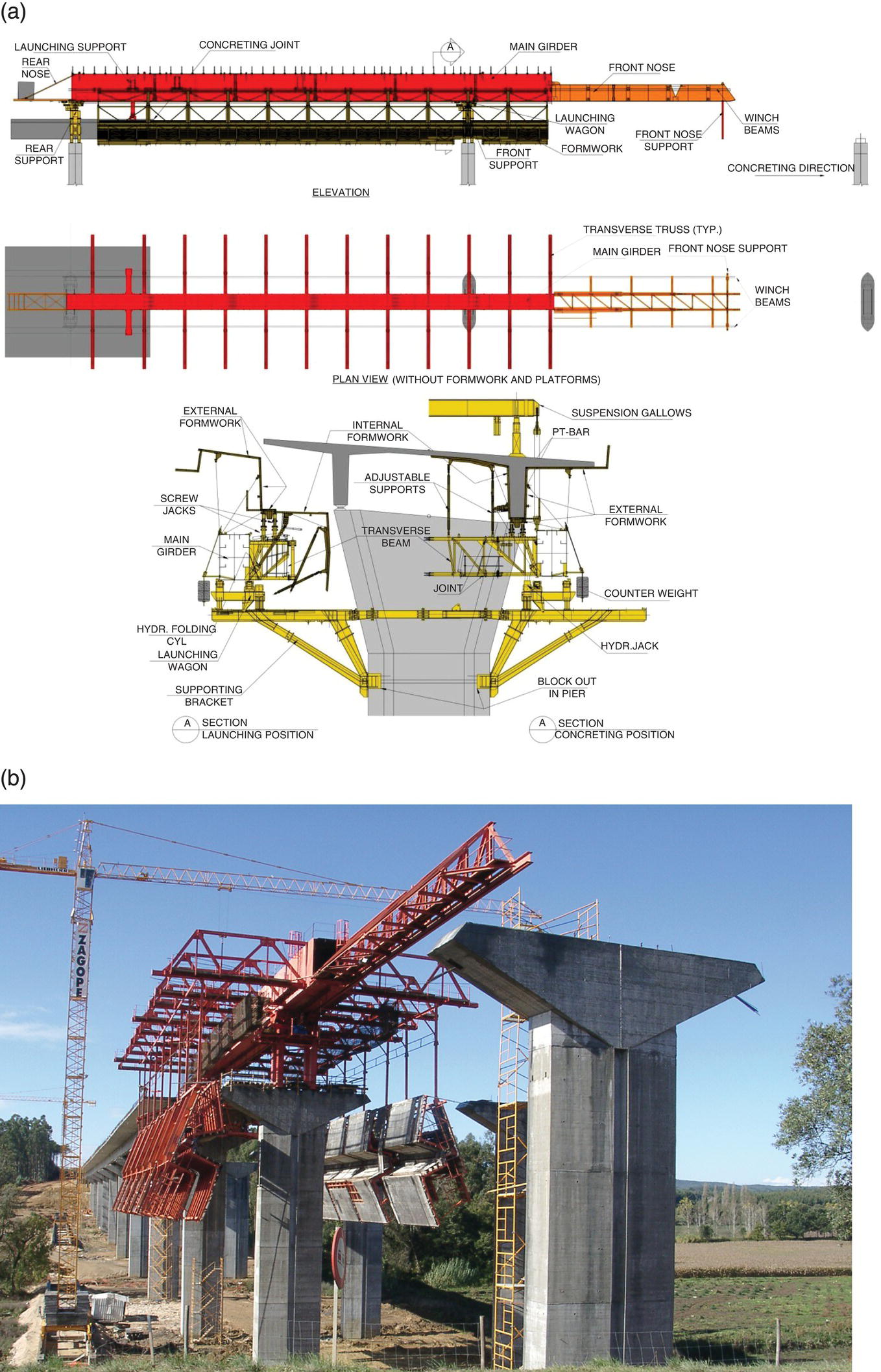
Figure 4.93 (a) Formwork launching girder working from above – Cross sections of the working stages (Ref. Strukturas Catalogue – Movable Scaffolding System); (b) The A15 Highway viaducts, Portugal.
Launching girders are adequate for long bridges (viaducts) with straight or curved in‐plane geometries and with multiple spans between 30 and 60 m. The deck cross section may be a ribbed slab, a slab girder or a box girder. The launching girders generally have a length corresponding to two spans of the deck or have a support at the part of the deck already built, as shown in Figure 4.92. They are equipped with one or two launching noses (one at the front and one at the back) to reach the next pier during launching operations (Figure 4.92). They are equipped with hydraulic devices to move the equipment forward and to install and re‐install the formwork as exemplified in Figure 4.92 and 4.93. The most convenient sections to be built with formwork launching girders are slab twin girder decks, with span lengths up to 45 m, allowing building of one span per week. For box girders, with spans between 45 and 60 m, the progress of construction is generally lower and approximately equal to one span every 10–12 days. Formwork launching girders working from below are usually more costly than formwork launching girders working from above, because the available space for the structural depth for launching girders working from above may be larger allowing a lightest girder. Truss girders may be adopted in this case. The steelwork required for launching girders is controlled by maximum deformability requirements. A maximum deflection of the launching girders in the order of 1/600 of the span length is usually required in design specifications. The main inconvenience of launching girders working from above is the constraints resulting from the hangers suspending the formwork (Figure 4.93) not allowing prefabrication of the reinforcing cages. Moving forward operations are usually more difficult than with formwork launching girders working from below. But, supporting the launching girders in the pier shafts (Figure 4.93) is usually more difficult for formwork launching girders working from below. Launching girders may also be adopted for precasted segmental construction (section 4.6.2.6) as shown in Figure 4.94.

Figure 4.94 Launching gantry working from above – Elevation and in‐plane view and cross sections of the working stages (Ref. Strukturas Catalogue – Launching Gantries for Segmental Bridges).
The cost of formwork launching girders is an investment that cannot be recovered without reutilization of this equipment. The adaptation to a new bridge cross section is usually possible but the span lengths cannot be much larger than that adopted for the original design of the launching girder.
4.6.2.4 Incremental Launching
Incremental launching is one of the most recent methods for the execution of concrete decks. It was initially developed last century in the 1960s [30, 32] and has been one of the most adopted methods in Europe in last decades.
The method consists of producing deck segments, usually between one‐third and half of the bridge span length, to the back of an abutment. After a certain bridge deck segment is completed, this is pushed or pulled forwards by hydraulic devices as shown in Figure 4.95. The reaction forces to move the deck forwards are induced at the abutment.

Figure 4.95 Incremental launching method for a concrete deck.
The method is usually applicable for long bridges with an in‐plane straight or constant curvature alignment (circular – R = const.) and with medium span lengths between 30 and 60 m. To reach one pier when pushing the deck forward at the rear section, a constant radius of the in‐plane alignment is necessary. Otherwise, a longitudinal movement induces a transverse deviation from the in‐plane alignment at the front section and the new pier support cannot be reached. However, the in‐plane alignment may be composed, for example, by straight and a circular alignments, but the deck should be pushed or pulled from both sides by executing one platform at the back of each one of the abutments. Intermediate launching platforms can be adopted to overcome the problem of in‐plane alignments made of more than two constant curvature bridge segments.
A front nose made of a plate or truss steel structure is necessary to reduce the bending moments at the front pier section as shown in Figure 4.95. The length of the nose is usually in the order of 50–60% of the span length. The same segment passes during the movement over support sections (negative bending moments) and at mid‐span locations (positive bending moments). The evolution of the static scheme during launching phases induces an envelope of bending moments as shown in Figure 4.96. The critical section for negative bending moments is of course at the last pier section before the nose landing at the pier. The nose may be equipped with a curved ‘landing device’ to facilitate support at the front piers.

Figure 4.96 (a) Evolution of the static scheme and (b) bending moments envelope during deck incremental launching.
In order to avoid tensile stresses in the concrete sections, the prestressing for the execution phase is likely to be centred and the cross section should have similar lower and upper section modulus. The ideal cross section deck is a single cell box girder. Span lengths of 30–60 m are the most adopted ones although longer spans are possible with intermediate piers or with a temporary staying scheme (Figure 4.97).

Figure 4.97 Temporary piers or staying device, reducing bending moments at front cross section during launching of the deck.
Temporary prestressing is required for the construction phases that may be done by external cables, some of them dismantled at the end before additional cables are added to support positive and negative deck bending moments at final stage.
Long bridges (more than 200 m length), or bridges with main spans crossing a river where no support from the ground is possible, may be executed by incremental launching at a construction progress of at least one segment per week. For segment lengths of half the span, one has at least one span made every two weeks.
For pre‐design, one may take the following guidelines:
- spans – 20–70 m, usual 35–55 m
- slenderness of box girder cross sections are l/h = 14–17 for road bridges and l/h = 12–15 for railway decks
- steel reinforcement quantity – 130 to 150 kg m−3
- prestressing quantities – 40–70 kg m−3
The length of the launching plant is at least one or two span lengths. The segments are cast in a formwork supported from the launching platform (Figure 4.98). Hydraulic jacks lower the formwork before the deck is moved forwards. Sliding supports under the webs are adopted as shown in Figure 4.98. The capacity of the launching equipment to move the deck is calculated on the basis of a friction coefficient (μ) of at least 5% and if the longitudinal profile has a positive slope i (%), which has to be taken into consideration when evaluating the required capacity of the hydraulic jacks, that is, μ > 5% + i. When the slope is negative, retaining cables have to be added to guarantee stability during launching operations. The most common jacking system to push the deck forwards is as shown in the scheme of Figure 4.99. Two jacks are adopted – a lifting jack reacting by friction at the deck underneath and a horizontal jack reacting against the abutment to induce the movement. The total dead load of the deck to be launched may reach some thousand tonnes (65 000 tons for the ship‐canal Bridge in Belgium [4]). Temporary sliding guided‐bearings are adopted at each pier for launching operations and made of PTFE plates with neoprene pads to accommodate rotations.

Figure 4.98 Formwork and falsework at launching platform.

Figure 4.99 Example of a hydraulic jack system for moving a concrete deck by incremental launching (Ref. Eberspächer launching system – site http://www.eberspaecher‐hydraulik.de).
4.6.2.5 Cantilever Construction
4.6.2.5.1 Basic Aspects
Historically, the cantilever construction method, developed initially for wood bridges, has taken its place in bridge engineering with cantilever construction of steel bridges. With the development of RC bridges, the method has attracted attention from bridge builders after the Herval Bridge over River Peixe in Brazil was built in 1930 by a construction technique similar to that adopted nowadays. Although Freyssinet had previously (1945–1950) adopted the cantilever method to some extent, it was only with Finsterwalder in Germany (1950–1951) that the cantilever method for PC bridges was similar to modern technology.
Cantilever construction is a segmental construction method where small segments, generally in the order of approximately 2.5–5.0 m length, are built and assembled from the end section of an already‐built deck cantilever. The segments may be cast in place or precasted. In the former case, a moving scaffolding and formwork (Figure 4.100a), attached to the last segment already built is needed. In the last case (Figure 4.100b), precasted segmental cantilever construction, the segments are positioned at the end section of the cantilever. For precasted segmental cantilever construction, the segments are positioned with a launching girder, lifted from a barge or from the ground with a derrick. The cantilever construction scheme may be executed:
- Symmetrically to each side of a pier – balanced cantilever scheme
- Asymmetrically, from a span already built
- Asymmetrically, from an abutment


Figure 4.100 (a) Bridge built by in‐situ concrete balanced cantilever system – The Zambezi River Bridge, Mozambique (137.5 m typical spans)
(Source: Courtesy GRID, SA)
or by (b) precasted segments – Oléron Bridge, in France
(Source: Photograph by Mutichou/ https://commons.wikimedia.org).
Usually, at the end span, a mixed technique is adopted as shown in Figure 4.3. The cantilever construction scheme (Figures 4.3 and 4.4) is adopted from the end pier for part of the end span and the remaining area is made with scaffolding supported from the ground.
In the cantilever construction method, cast in place or precasted segments are prestressed at each phase after casting or assembling a new segment (as shown later in Figure 4.101).

Figure 4.101 Cantilever and continuity prestressing cable layout.
The connection between the end sections of each one of the cantilevers coming from two piers of one span is made through a closing segment with a general length between 2 and 3 m. Continuity prestressing cables (Figure 4.101) are applied after casting of the closure segment to face the induced bending moments at mid‐span sections, developing in the continuous structure as explained in Section 4.3. Part of this prestressing may be made by external cables.
The dead weight of each cantilever and the weight of the moving equipment (scaffolding and formwork) is supported in bending by the already completed part of the cantilever. Figures 4.102 and 4.103 show moving scaffoldings for cantilever construction. The moving scaffoldings are usually designed for capacities between 250 and 750 kN and standard maximum segment lengths of 5.0 m.

Figure 4.102 Moving scaffolding for cantilever construction with cast in place segments working from above (Ref. Strukturas – Form traveller for cast in situ bridge decks).

Figure 4.103 Moving scaffolding for balanced cantilever construction in Quintanilha Bridge (multiple spans of 80 m), for maximum weight segments of 1700 kN with 5.0 m lengths.
(Source: Courtesy GRID, SA)
Large negative bending moments exist during the cantilever scheme. The most adequate section to resist these bending moments is, of course, a box girder section due to its large lower flange. The box girder is in most cases a single cell box girder with vertical or inclined webs. For very large width sections, a double cell box girder may be adopted, or a single box with inclined struts or with transverse ribs.
The depth of single cell box girder at pier sections for cantilever construction is between 1/20 and 1/17 of the span length. A maximum slenderness of 1/22 at the support sections may be adopted for aesthetics (Figure 5.14 – Alcacer do Sal Bridge at IP1 over the River Sado, Portugal) when the vertical alignment is at a low level.
In balanced cantilever schemes, the piers (Figure 4.104) resist the differences between the moments coming from each cantilever. These differences result from deviations in weight of the segments, and possible asymmetry in concreting the segments, construction loads and wind loading. The quantification of these loadings is addressed in Chapter 6.
Figure 4.104 Bending moments to be resisted by piers in balanced cantilever schemes.
The connection between the piers and the deck to resist these moments during construction may be monolithic in frame bridges, connected through anchorages by prestressing cables or supported by temporary piers (Figure 4.105) in the case of continuous girder decks supported on bearings.

Figure 4.105 Possible schemes to resist unbalanced moments from the cantilevers.
4.6.2.5.2 Span Arrangement for Balanced Cantilever
In continuous multiple span decks, the easiest solution for span arrangement is to make, as far as possible, multiple internal span lengths (l) and two end spans with lengths in the order of 0.6l to 0.8l. Some examples are shown in Figure 4.106a. In the Porto Novo Viaduct (1988), 80 m typical internal spans with a constant depth (4 m) and two side spans of 60 m with a reducing depth towards the abutments were adopted. For the internal spans, the balanced cantilever was executed from each pier and a sequence of closure segments from the side spans to the centre was executed. At the end piers, 38 m deck lengths to each side of the pier were executed and the remainder 20 m of the side spans (20 m) between the abutment and end cantilever were executed on a scaffolding from the ground. Then closure segments were executed in the first and last spans, followed by the closure segments at the second and fourth span and, finally, the centre closure segment. The evolution of the static scheme is similar to that already discussed in Section 4.3. In the bridge over the Zambezi River in Caia, Mozambique, with 137.5 m internal typical spans, the end spans are 80 m and a sequence of closure segments was executed from the side spans to the centre, see Figure 4.106b. Details on this long bridge (2376 km) and sequence of construction may be seen in [33]. When different internal spans are adopted as in the Rosso Bridge over the River Senegal (Figure 4.106c), with a main span of 120 m over the main channel, the balanced cantilever scheme can also be adopted but the span distribution should be established taking into consideration the sequence of closure segments. In a sequence of internal spans, l1, l2, l3,…, for a general symmetrical arrangement as shown in Figure 4.106c, a balanced cantilever scheme from piers P1, P2 and P3 requires, for example, l2 = (l1 + l3)/2.

Figure 4.106 Span arrangement for balanced cantilever construction with equal internal spans (a) Porto Novo Viaduct in Madeira Island with 80 m spans, (b) Bridge over Zambezi River in Caia Mozambique with 137.5 m spans) and with different spans internal spans and (c) Rosso Bridge over river Senegal (tender design), with a main span of 120 m for the main channel).
4.6.2.5.3 Asymmetric Cantilever Construction
Site data, like topography, geotechnical conditions or a main span over a river, may justify adopting an asymmetric (unbalanced) cantilever scheme. An example of a design case [34] of two parallel bridge decks is shown in Figure 4.107 The topography and geotechnical conditions of the valley have shown the best option to be a deck for each of the bridges built from a single pier in a balanced cantilever scheme and the remaining part of the deck from the tunnel as a single cantilever in an unbalanced scheme. The closing segment was then executed at the centre of the main span of 104 m. Site conditions showed the location of the single pier for each of the decks to be skew symmetric, as shown in Figure 4.107. The bridge is curved in‐plan and the pier is made of two thin RC walls. The deck is made monolithic with the pier, which allows the imposed deformations (thermal, shrinkage and creep) by flexibility of the two shafts of the deck, rigidly connected at the tunnel and having unidirectional bearings at the abutment. The bridge, with two spans for each of the decks, from the front view looks like a classical three‐span bridge. The reader is referred to Ref. [34] for details.

Figure 4.107 An asymmetric cantilever construction. The Bridge over Vigario Creek in Madeira Island.
(Source: Courtesy GRID, SA)
4.6.2.5.4 Frame Bridges with Inclined Piers and Arches
For frame bridges with inclined piers, usually hydraulic jacks are inserted between the deck and the temporary piers (Figure 4.108) for removing the temporary supports after closing the deck at the mid‐span section. The cantilever method may be also adopted for the construction of arch bridges. The reader is referred to [35] for developments on the cantilever construction method.

Figure 4.108 Cantilever construction scheme for a frame bridge with inclined piers.
4.6.2.6 Precasted Segmental Cantilever Construction
It has been already mentioned that precasted concrete segments can be adopted with launching girders and cantilever construction. This is a very convenient alternative for multiple span long bridges, because segments are being executed and at same time others are being assembled. The rate of construction may reach an average of 10 m of deck per day. If one compares it, for example, with a cast in situ cantilever scheme, with two pairs of movable false work where it is possible to build 20 m week−1 (2 × 2 segments of 5.0 m length), the speed of construction with precasted segments is at least twice the one achieved with a cast in‐place cantilever scheme.
The length of segments is up to 3.5 m in general, limited by transport, lifting and assembling capacities of the equipment and the amount of prestressing required at each assembling stage. They are precasted on site or in a specific facility and transported to the bridge site. The most adopted method for precasting is ‘match cast’ segmental construction, where the segments are cast one against the other in order to achieve a coupled joint (Figure 4.109). The segments are then assembled on the alignment of the bridge deck, by cranes (if the height of the bridge deck allows), via a launching girder or the cantilever method.

Figure 4.109 Precasted segmental construction with match cast joints.
An important issue in precasted segmental bridges concerns the joints between segments. The three possible options are cast in situ joints (requiring approximately 200 mm for the joint and a formwork), mortar joints allowing a reduction in the gap between segments to approximately 5 cm and, finally, coupled match cast joints with ‘epoxy’ glue. The last procedure is nowadays the most adopted one due to the quality usually achieved and the rate of construction allowed. In coupled match cast joints, the ‘epoxy’ allows lubrication of the contact surfaces of the segments facilitating the assembling and, most important, seals the joint allowing waterproofing, thus avoiding the water ingress into the ducts of the prestressing cables crossing the joint. The joints are designed to be permanently compressed even under live loads and thermal gradients. The shear resistance is achieved nowadays by a multiple ‘shear key’ detail, as shown in Figure 4.109, improved by the presence of the ‘epoxy’. The reader is referred to Refs. [4, 26, 35, 36] for details and specifications on precasted segmental construction.
4.6.2.7 Other Methods
A brief reference is here made to other possible options for execution of concrete bridge decks. Three additional methods are:
- Deck erection by transverse displacement
- Deck erection by rotation
- Deck erection by heavy lifting equipment
One is the possibility of executing the bridge deck on a site parallel and adjacent to the in‐plane bridge alignment and moving the deck laterally after completion, previously erected on sliding bearings, by hydraulic equipment. The transverse sliding method is adopted for small bridges and usually when replacing an existing deck where severe traffic disruption is a main constraint.
Rotation of the deck built on site is, perhaps, the most spectacular bridge erection method. The deck may be executed, for example, along a river bank on scaffolding supported from the ground and then rotated to the final bridge alignment. It is adopted for the same span range spans of the cantilever method since during rotation the static system is similar. Yet, this method has been already adopted for cable‐stayed bridges like Ben‐Ahin bridge, Belgium [4].
Heavy lifting erection methods have been developed in the last few decades for long bridges offshore or crossing long estuaries like the Great Belt Bridge in Denmark, Vasco da Gama Bridge in Portugal, and the Prince Edward Island Bridge in Canada. Precasted entire spans may be transported on barges to the site and lifted with special equipment: gantry cranes, reaching capacities of several thousand tonnes. In the Vasco da Gama Bridge, entire 80 m box girder spans were transported and lifted and for the Prince Edward Bridge, with multiple spans of 250 m, segments reaching 7800 tons were erected. The construction rate with heavy lifting is the largest, generally reaching 250 m per week for the Prince Edward Bridge [31].
4.6.3 Erection Methods for Steel and Composite Bridges
4.6.3.1 Erection Methods, Transport and Erection Joints
The most adopted methods for the erection of the superstructure of steel and composite bridges are:
- Erection from the ground with cranes
- Incremental launching of the steelwork
- Cantilever construction
The last method, cantilever construction, is adopted for long spans as for concrete bridges, namely for box girder bridges and cable‐stayed bridges. Specific methods, such as the ones referred to for concrete bridges in Section 4.6.2.6, like transverse displacement and rotation, are also adopted in a more limited range of applications. The fundamentals of the methods are similar to the ones already mentioned for concrete bridges. One of the specific aspects of steel and composite bridges is transport to the site of the steelwork. After fabrication, a main issue is how the steelwork should be transported to the bridge site. This aspect has been already mentioned in the introductory section on steel bridges (Section 4.5) but is also related to the erection procedures. The most common transportation is by trucks, but without special permissions a segment limit in the order of 30 m length and 3 m width by 4 m height is imposed in most countries. The weight of the segment is usually limited to approximately 50 tons. Rail and ship or barge transport is a possible option in some cases, with segment lengths limited to approximately to 12 m for railway transport and container limitation for ship transport.
Plate girder steelwork decks are generally transported in independent girders, the number of segments being limited to a maximum total weight of approximately 40 tons for the truck. Box girders are transported in two halves (Figure 4.35) requiring a longitudinal site joint as previously referred to.
The segments after transport to the site may be assembled in longer segments by execution of full penetration welding joints at flanges and web sections that are subjected to Non Destructive Testing (NDT) on site. The quality welding control on site is currently done by ultrasonic or magnetoscopic tests and less frequently by RX tests. Of course, basic geometric quality control, visual inspection of the welding and dye penetrant tests are always done.
The segments are then erected and positioned at the deck alignment and bolted or welded at erection joints. The tendency nowadays is to prefer welding erection joints for the benefit of durability of the structure but, of course, this requires the appropriate means for site execution and inspection. The number of NTDs to be carried out on‐site inspection depends on the Execution Class (EXE) of the structure according to EN 1090 [37]. For bridges, EXE 4 is required in most cases and for site welding:
- Transverse butt weld subjected to tensile stresses 100%
- Transverse fillet welds, in general 10%
- Longitudinal welds and welds to stiffeners 10%
In a span‐by‐span erection, it is possible to have erection joints at intermediate span sections, for example, at one‐fifth span sections, and to execute complete penetration site welding on webs and flanges. For most cases, bolted temporary erection joints are needed, which could be done according to the scheme of Figure 4.110. After final adjustment of the new segment position the definitive site welding is executed.

Figure 4.110 Erection of the steel work with cranes on the ground, temporary supports and erection joints.
4.6.3.2 Erection with Cranes Supported from the Ground
If the height of the deck with respect to the ground is relatively low (order of less than 15 m) and access to bridge site allows, it is possible to erect the steelwork with cranes from the ground. The crane capacity is dependent on the lever arm required and on the weight of the segments of the steelwork. A reference value of 100 tons at maximum distances of 10–20 m may be considered for standard crane erection of the steelwork. The deck may be erected by a span‐by‐span scheme with erection joints as discussed in Section 4.6.3.1.
For a main span on a river, it is possible to erect the central part of the steelwork by cranes on barges, or even with two cranes located on each river bank as in the example of Figure 4.111.

Figure 4.111 Erection by cranes of the main segment of the central span of Lanaye bridge in Belgium with a main span of 72 m (Depth of the steel box girder 2.1 m).
(Source: Courtesy BEGreisch, SA)
4.6.3.3 Incremental Launching
The incremental launching method for the erection of the steelwork is, concerning its basic aspects, constraints, advantages and disadvantages, quite similar to the incremental launching method for concrete bridge decks discussed in Section 4.6.2.4. The erection scheme is as represented in Figure 4.95 for concrete decks. The segments of the steel deck coming from the manufacturer are positioned along a launching platform, welded at the end section of the previously launched segment and moved forward, by pushing or pulling, by hydraulic devices.
Long straight alignments or curved with constant curvature steelwork decks, with spans up to 150 m, may be incrementally launched. Longer spans are possible with intermediate temporary piers or staying schemes during launching (Figure 4.96). The span length is one of the main differences with respect to the incremental launching of concrete bridge decks, where spans above 60 or 70 m are very difficult to launch due to the deck dead weight inducing too large internal forces during erection. The incremental launching method of steel and composite decks (Figure 4.112) requires:
- a launching platform with a minimum of two span lengths
- an hydraulic device system for pulling or pushing the steelwork
- temporary bearings at all piers and guiding devices
- a launching nose equipped at the front with a ‘landing device’ or with the possibility for lifting the end section from the pier

Figure 4.112 Incremental launching of the railway deck of (a) the access viaduct of Tagus Suspension Bridge in Lisbon (launching nose) and (b) Sado Viaducts (typical spans of 76 m and 45 m, respectively).
(Source: Courtesy GRID, SA)
The capacity of the hydraulic devices system is usually between 3 and 10% of the weight of the steelwork. Temporary sliding bearings at piers are shown schematically in Figure 4.113. The friction coefficient is for design purposes at least 5%. If the geometric slope of the longitudinal profile is, for example, 2% as in case of Figure 4.112a, an equivalent friction to 7% is considered. Launching stages in the order of 2 h for 20 m segments are typical, as in the case of Figure 4.112a.

Figure 4.113 Temporary bearings scheme, for incremental launching.
(Source: Adapted from Ref. [19])
When the deck approaches a new pier, the vertical deflections at the front section of the launching nose requires either a special type of device – a landing device – or the possibility of lifting the end section of the nose upwards. Introducing upward movements in the order of 200–300 mm is usual. All these deflections induce internal forces and the final precamber to adopt for the deck should be determined at design stages. Patch loading in the webs (Figure 4.63) under combined shear and bending moments should be checked at all erection stages and critical sections.
The deck is usually launched at its final level or at level of the lower flange and then moved downwards to its final position. In a twin girder deck, both girders are launched simultaneously, in general and if needed, with a temporary transverse horizontal bracing, usually at level of the upper flanges. The transverse stability of both flanges should be checked at the erection stages taking the distance between diaphragms restraining horizontal transverse buckling of the compressed flanges into consideration.
4.6.3.4 Erection by the Cantilever Method
The cantilever method, already discussed for concrete bridges, is the most adaptable method for erection of steel decks of large spans (more than 100 m) and with or without a variable curved in‐plane alignment. The segments are erected by derrick devices at the end section of the cantilever, from the ground or from a barge in a river. The length of the segments may be much longer than in concrete bridges, reaching 15–20 m in length. The method is adopted based on a balanced cantilever scheme or by an asymmetric scheme as shown in Figure 4.114a. At closure of the segment section (Figure 4.3), the bending moment due to dead loads is zero when the erection joint is done by site butt welding of flanges and webs, and it remains zero contrary to what happens to concrete bridges, as explained previously in Section 4.3.

Figure 4.114 (a) Balanced cantilever schemes for the erection of a prestress concrete decks and (b) asymmetric scheme for the erection of steel and composite cable‐stayed decks.
For very long spans, intermediate temporary piers or staying schemes are adopted. Cable‐stayed bridges with steel, concrete or steel‐concrete composite decks can also be erected by the cantilever method (Figure 4.114b).
4.6.3.5 Other Methods
Other methods, like the ones referred to for concrete bridges, are possible. In particular, transverse sliding [19] is very much adopted for replacement of an existing steel deck when, in railway bridges (in particular), traffic interruption is a main constraint. Another option is erection of a central part of a long main span (Figure 4.115) from a barge with heavy lifting equipment or of a bowstring arch in three segments, as in Figure 4.116.

Figure 4.115 Erection from a barge of a 162 m length segment, of the main span (242 m) of Cheviré Bridge over Loire River in France.
(Source: Adapted form Ref. [38])

Figure 4.116 Erection of the arches in the bowstring railway bridge over river Sado, in Portugal.
(Source: Courtesy GRID, SA)
4.7 Substructure: Conceptual Design and Execution Methods
4.7.1 Elements and Functions
A bridge substructure integrates piers, abutments and foundations. Its main function is to transfer to the ground the loads of the superstructure. The substructure should constitute, along with the superstructure, an integrated stable and resistant system complying with the imposed displacements of the superstructure due to thermal deck movements, creep and shrinkage effects of concrete decks, prestressing actions and settlements of foundations.
The abutments make the transition with the earthfill of road or railway approaches. Bridge bearings are introduced, in general, between the superstructure and the abutments, but small bridges may be made with integral abutments monolithic with the superstructure [39].
From an architectural point of view, piles and abutments should be carefully studied due to their importance on bridge aesthetics and surroundings integration, as discussed in Chapter 5.
4.7.2 Bridge Piers
4.7.2.1 Structural Materials and Pier Typology
Piers may be made in masonry, wood, concrete or steel. Masonry piers have been adopted for a long time, since bridges were first made. The lack of tension resistance is one of their main limitations. Even in the middle of last century, beautiful bridges (Figure 4.117) were made with masonry piers and engineers should be aware of masonry as structural material. Effectively, retrofitting of old bridges very often requires replacement of the deck keeping the existing piers for economy but, most importantly, for respecting historical heritage. It should be borne in mind the resistance of a hard stone may reach 50–100 MPa, while standard masonry due to the influence of the mortar may be limited to values 5–10 MPa. However, this depends very much on the case, and values for compressive stress resistance from tests of prismatic specimens of masonry for the piers of the bridge in Figure 4.117, with joints of 3–4 cm, can reach minimum values as high as 70 MPa [40].

Figure 4.117 Bridge in Caniçada dam with masonry tubular piers (0.30–0.40 m thickness) reaching 60 m height as designed by E. Cardoso in the 1950s.
(Source: Photograph by José O. Pedro).
Wood piers are adopted in wood and temporary bridges. It is also adopted as a structural material for scaffoldings in bridge construction. However, the majority of bridge piers nowadays are made in RC. Some prestressing is adopted in some cases but currently compressive stresses due to permanent loads are enough to balance any tensile stresses due to variable actions. In any case, if tensile stresses are induced due to live loads or imposed displacements, the problem is overcome, in most cases, with just ordinary reinforcement. RC is an excellent structural material for piers, since the main actions induce compressive stresses, and reinforcement steel is required to limit crack widths and for ULS resistance due to induced tensile stresses under the combination of compression and bending due to permanent and variable actions.
A pier shaft with its foundation is shown in Figure 4.118. If the pier has a double shaft, or more than two shafts, a transverse cross beam, capping beam, between pier shafts may be needed for transverse stability (Figure 4.119). Although not very aesthetically pleasant, the cross beam yields a transverse frame action to the pier.

Figure 4.118 Elements of concrete pier with a single shaft.

Figure 4.119 A pier with a double shaft.
The geometry of cross section of bridge piers may be quite diverse and it is possible to define the following typologies:
- solid section piers or tubular piers – column piers (Figure 4.120)
- wall piers – leaf piers (Figure 4.121)
In column piers, cross sectional dimensions a and b (Figure 4.120) are of the same order of magnitude, usually in the order of 0.5–1.0 m. For pre‐design of the cross section, an average medium compressive stress at SLS in the order of 4–5 MPa may be adopted. In leaf piers, the width a is much larger than the thickness b, usually at least four times. In this case, b is generally between 0.4 and 1.0 m and the width a is very often reduced towards the base section for aesthetics and sometimes to increase horizontal clearances at the ground level, namely in urban viaducts. An average compressive stress at SLS in the order of 2–3 MPa may be adopted. At the top section, cross sectional dimension a is dependent on bearing location requirements in most cases. For piers with a single shaft, and heights up to 15–20 m in general, column piers (Figure 4.120a) are usually preferred. For medium piers, say between 20 and 30 m, solid or tubular box sections may be adopted. Above 30 m and sometimes reaching 200 m height or even more (Figure 4.33 – Viaduct the Millau), tubular piers (Figure 4.120b) are the preferred option. The wall thickness is in general at least 30 cm for easiness of formwork and placement of reinforcement.

Figure 4.120 Column Piers: (a) solid section and (b) tubular piers.

Figure 4.121 Leaf (wall) piers.
4.7.2.2 Piers Pre‐Design
Designing pier shaft cross sections should take into consideration:
- resistance
- stability
- aesthetics
Stability should be considered at the final static model of the bridge and also at construction stages. Its overall cross section dimensions are kept constant for short and medium piers, say up to 30–40 m. In tubular tall piers, at least one of the cross sectional dimensions, usually the transverse dimension, is variable (see Figure 5.17).
The slenderness of a pier for aesthetics is usually defined as l/b or l/a, l being the pier height of its shaft and b or a the overall cross section dimensions (Figure 4.120). For stability, slenderness is defined by:
where le is the buckling length and i is the relevant radius of gyration of the pier cross section. The radius of gyration ![]() , where I is the relevant moment of inertia and A the cross sectional area. For a rectangular section,
, where I is the relevant moment of inertia and A the cross sectional area. For a rectangular section, ![]() or
or ![]() . This means the slenderness for aesthetics is approximately 28% of slenderness for stability. Assuming b is the smaller dimension of a constant rectangular cross section, a pier with l/b = 20 has λ = 70 if le = l. At the final static model of the bridge, one may have from le = 0.5 l if the pier is monolithic to the deck, up to le = 2 l if a sliding bearing is adopted between the deck and the top of the pier shaft. At the construction stage, one very often has le = 2 l, or even more if rotation at connection with foundations is considered, as discussed in Chapter 7.
. This means the slenderness for aesthetics is approximately 28% of slenderness for stability. Assuming b is the smaller dimension of a constant rectangular cross section, a pier with l/b = 20 has λ = 70 if le = l. At the final static model of the bridge, one may have from le = 0.5 l if the pier is monolithic to the deck, up to le = 2 l if a sliding bearing is adopted between the deck and the top of the pier shaft. At the construction stage, one very often has le = 2 l, or even more if rotation at connection with foundations is considered, as discussed in Chapter 7.
A basic pre‐design criterion for selecting the cross sectional dimension of a pier section is to limit its slenderness to 70 for the final static scheme and 100 during construction. A limit of 70 at the final static scheme is adopted to avoid relevant creep effects of the concrete on the ultimate buckling resistance of the pier. For tubular piers, if one compares its cross section with a solid section pier with same cross section area, one has a larger radius of gyration i. That is why tubular sections are preferred for high piers. In tubular piers one has, compared to a solid section pier with the same cross sectional area, A, a more stable shaft (smaller λ) and the same compressive stresses due to axial loads, which is relevant to reducing tensile stresses coming from imposed permanent actions due to creep and shrinkage and variable actions.
The slenderness of a concrete pier is generally smaller than in a steel pier, and second order effects due to instability effects govern this. RC piers are always adopted in concrete bridges and are the main option for steel and composite bridges. In piers in rivers, it is usual to adopt wall piers, with hydrodynamic details as shown in Figure 4.121. If the risk of ship impact exists, the cross sectional dimension b of a wall pier may be larger than 3 m. In those cases, ship impact defences (‘fencers’) may be adopted. A similar case occurs in viaducts over railways where wall piers are usually required and minimum distance to tracks should be respected [41]. In short, whenever an accidental impact event in pier shafts due to traffic needs to be considered, possible options for design are:
- to locate the pier at a sufficient distance to minimize risk of impact
- to adopt pier protections (fences in rivers, walls nearby tracks, metal fences near road traffic lanes)
- to design the pier shaft for impact loading
The risk of ship impact in piers depends on the dimensions, tonnage and speed allowed of the vessels in the navigation channel. Ship impact, reaching thousands of kN, tends to be the critical action for the design of piers in rivers.
Design of pier shaft cross sections should take into consideration resistance, stability and aesthetics. Overall cross sectional dimensions in piers are kept constant for short piers, say l < 10–15 m, and medium piers, say 15 m < l < 40 m. In tubular tall piers, at least one of the cross section dimensions, usually the transverse dimension, is variable.
One important aspect when designing pier cross sections is the dimension required for the bearings as indicated, for example, in a leaf pier in Figure 4.121. Besides, the space required for hydraulic jacks for replacement of bearings is another aspect to be taken into consideration.
4.7.2.3 Execution Method of the Deck and Pier Concept Design
The execution method of the deck may influence the shape of the pier shaft. In incremental launching girders working from below, the upper part of the pier shaft should be designed to accommodate the fixation devices of the launching girders as shown in Figure 4.92. In the incremental launching method, the pier top cross section requires sufficient clearance to accommodate temporary bearings and transverse guiding devices to avoid deviations of the in‐plane alignment during launching operations. Besides, the pier shaft should be designed to withstand the horizontal forces due to bearing friction during launching or even due to the longitudinal slope of the bridge deck. However, from all execution methods for the bridge deck, the cantilever method for deck execution generally has the largest impact on the concept design of piers. By this reason, it is dealt with specifically in the following.
4.7.2.3.1 Piers for Bridges Built by Cantilever Construction
Actions induced in bridge piers built by balanced cantilever during construction are due to a multiplicity of actions (Figure 4.122), namely:
- dead loads (pier and deck)
- unbalanced segments during construction
- dead loads of moving travellers (scaffoldings)
- construction live loads
- wind loads

Figure 4.122 Example of design loads for piers during cantilever construction of the box girder deck (b – deck width, v – design construction wind speed).
All these loads induce large axial loads and bending moments (in two directions) and are easy to resist with tubular column piers. In tall piers, second order effects due to instability come into play and may be relevant, as will be discussed in Chapter 7.
The connection between the pier and the deck may be rigid (frame bridges) or through bearings (continuous girder bridges), as shown in Figure 4.123. Bending moment resistant of the piers is usually adopted for tall piers to avoid bearings, and temporary devices for stability during construction and to benefit from frame action at the final static scheme.

Figure 4.123 Monolithic and simply supported decks of box girder bridges built by cantilevering – support sections.
(Source: Courtesy GRID, SA)
Short piers are usually connected to the deck through one single row of bearings. Temporary anchorage, stay cables or temporary piers (Figure 4.124) are needed to guarantee a stable system during the erection stages.

Figure 4.124 Temporary stability systems – anchorages, temporary piers and stay cables for overall stability of the deck during cantilever construction stages. Sorraia River Bridge. Main span 120 m.
(Source: Courtesy GRID, SA/José Pedro)
Medium height piers are usually provided with one or two rows of bearings reducing the stiffness of the pier for imposed deformation (creep, shrinkage and temperature) of the deck; in long continuous bridges, the central piers are usually rigidly connected to the deck, while the remainder have fixed pot bearings or unidirectional movable pot bearings. In some cases, a pier made of two flexible concrete shafts (Figure 4.107 and 4.125) is adopted, which are stabilized during the erection stage by a temporary steel structure, as will be discussed in the following.

Figure 4.125 Pier made with two slender pier shafts.
In short, there are three main possible options for typology and schemes of pier‐deck connections:
- tubular monolithic piers with the deck
- tubular or solid section piers (depending on height) supporting the deck by bearings
- piers made by two independent solid section shafts monolithically connected to the deck or eventually hinged at the deck
Stability in the first case – monolithic tubular piers – adopted for tall piers, may guarantee stability during construction phases by resistance of the tubular section shaft. The second case, a deck being articulated to the pier shaft, requires specific devices of course, as said before, guaranteeing overall stability of the deck. There are the following options:
- adopt temporary high strength prestressing bars or cables connecting deck and pier sections
- adopt one or two temporary piers adjacent to the definitive pier shaft
- adopt temporary stability cables (stays) anchored to the deck and to pier foundation
Finally, the option of adopting a pier with two slender pier shafts (Figure 4.125) is a possibility when the imposed displacements by the deck tend to induce large forces. In a pier made of two flexible shafts, any unbalanced moment M during construction is taken by a couple effect; no tensile stresses are usually accepted in the section at any construction stage, except for accidental load combinations. The shafts shall be sufficiently braced between them in such way that the full section works as a global section during construction stages. After closing the deck, the bracing system is removed and the shafts can deform as independent piers towards the centre of stiffness, as shown in Figure 4.125. The buckling length of the shafts at the built structure tends to be half the free length. During construction, the two pier shafts work together and the buckling length is taken for the pier with the overall cross section inertia.
The temporary stability systems referred to here – anchorages, temporary piers and stay cables – should be designed to guarantee the necessary overall stability of the deck and to have sufficient stiffness for good control of deflections during construction. Any rotation of the deck at support section has a large impact on deflections of the cantilevers, and precamber control becomes difficult to achieve. Sometimes, the three schemes (as before – anchorages, temporary piers or stay cables) are combined (Figure 4.124). It is usual to adopt anchorages and temporary piers or anchorages and stay cables due to lack of space at the top section of the pier in order to introduce a sufficient number of anchorages to guarantee overturning stability of the deck until the casting of the closure segment. Stay cables are very often sufficient for stability of the deck during execution but are not very efficient concerning deflection control (camber) because the deformability of the stays is usually too large. The use of temporary supports, if possible, is usually simpler and more efficient. The anchor bars for temporary connections between segment 0 and the end section of the pier are always required.
All these stability devices are designed for forces coming from overturning moments of the deck. Temporary bearings or wood shims are usually adopted in the anchorage scheme system between the underneath of the deck and top of pier section. At the end, after the closure segments are executed and stability of the deck is guaranteed, the anchorages and any temporary devices are removed.
4.7.2.3.2 Design Safety Checks of Piers During Deck Cantilever Construction
Actions during construction stages, referred to in Section 3.19, have been mentioned in the present chapter. For designing bridge piers built by the cantilever method, or the stability devices previously referred to, some specific construction loads and load combinations need to be specified. The basic system is represented in Figure 4.122, where Gi and Gi′ denote the weights of segments i and i′. The weights of each cantilever are G = ∑ Gi and G′ = ∑ Gi′. For Gmax and Gmin, one usually takes a ±2% deviation on the nominal weight, G, of one of the cantilevers; that is, Gmax = 1.02 G and Gmin = 0.98 G. Construction loads (equipment, formwork travellers, construction live loads etc.), are denoted by Qc1, Qc2 and Qc3, in Figure 4.122. Load Qc1 denotes a live load during construction, applied anywhere, Qc2 is associated with a construction load at the end segment due to weight of prestressing equipment (cables, anchorages, etc.) and Qc3 denotes the weight of the form traveller (500–800 kN in general). Wc designates an uplift differential wind action between the cantilevers.
Safety should be checked involving stability systems, for a load combination:

where G are permanent loads, Qci construction loads and Wc unbalanced wind loading. Partial safety coefficients γg = 1.1 or 0.9 as most unfavourable and γq = 1.25 have been proposed in [26, 42, 43].
An accidental load combination should also be checked replacing Eq. (4.16) by

where Fa represents the action induced by the falling of a form traveller during a manoeuvring or the falling of a precasted segment during erection, with a dynamic coefficient of 2.
In cast in‐place balanced cantilever bridges, sometimes in Eqs. (4.16) or (4.17) one considers a construction load Qci associated with a difference in weight between the end segment n and n′ due to a differential time between castings. To take Qci = 0.5 Gn where Gn is the dead weight of segment n is, in general, enough, provided the concreting of the slab deck in one side is not initiated before the bottom flanges and webs at both sides are concluded. This control, to be made by the Engineer, is sufficient because in box girder bridges the deck slab weighs about 50% of the full weight of the segment. Even with Qc = 0.5 Gn applied at the end section of only one of the cantilevers, the associated load combination tends to be the most critical for the pier, at least for long span balanced cantilever bridges.
During the balanced cantilever scheme of a curved box girder bridge (Figure 4.126), the dead load of the deck induces transverse bending moments in the piers, unless some provisional prestressing, internal or external, is adopted. It is possible to balance the total applied transverse bending moments during construction by external prestressing tendons applied with an effective force P and eccentricity e (Figure 4.126).

Figure 4.126 Pier actions in balanced cantilever bridges with a curved in‐plane alignment.
(Source: Courtesy GRID, SA).
Balanced cantilever bridges, with tall piers, present low natural frequencies in bending and torsional modes of the piers during construction. It is usual to have longitudinal and transverse bending frequencies and torsional frequencies fx, fy and ft, respectively for tall piers (say between 60 and 100 m) and spans between 100 and 180 m in the range 0.1–0.4 Hz. An example was shown in Figure 4.4 where fx = 0.17 Hz and ft = 0.29 Hz.
Under random excitation and due to wind gusts, bending and torsional effects due to unbalanced wind buffeting should be considered in designs when checking the structural safety during the construction stages. For torsional effects, the historical Sir Benjamin Baker's rule‐of‐thumb, as considered in the design of the Firth of Forth Bridge, assumes a ‘full mean wind’ with a wind velocity vm on one overhang and ‘no wind’ on the other [43] as wind pressure Wc2 shown in Figure 4.122. This load needs not to be combined simultaneously with normal construction loads, since it is unlikely construction is being done at a strong wind event. The pioneering work of Davenport [44] in 1967 evaluates the torsional effects induced by wind gusts on a cantilever bridge due to the resonant component of the torque only. Dyrbye and Hansen in 1996 [45] presented an approach suitable for design practice to consider the problem of torsional effects of balanced cantilever bridges of constant height decks. The approach was generalized by Mendes and Branco [46] for variable depth box girder bridges, as well as for the joint analysis or bending and torsion effects. Codes and design recommendations, like ASCE 1982, ECCS 1989 and NBCC 1990, refer to the need to investigate the wind torsional effects in balanced cantilever bridges during construction.
The characteristic average wind speeds (Uk,50) are usually defined for time intervals of 10 minutes with a reference period of 50 years. For checking the structure during construction, one adopts a shorter reference period T, say T = 10 years for a construction time not greater than 1 year according to EN 1991‐1‐4. The associated characteristic averages wind speed yields for T = 10 years Uk,T = 0.88 Uk,50, that is, a 12% reduction in wind velocity representing in the wind pressures (depending on U2) a 23% reduction. The reader is referred to specific literature [45] on this subject for further information.
For the design of temporary stability devices, one should take into consideration the uplift condition at a temporary pier or the minimum prestressing force required for temporary stays. The reader is referred to references [35, 45] for additional information.
4.7.2.4 Construction Methods for Piers
Piers are usually built by griping formwork. The formwork for the shaft with 3–4 m length, is moved upwards in steps discontinuously, after concreting the previously segment of the shaft. It is fixed to the part of the pier shaft already built and moved upwards by hydraulic devices. Then, after erection of the steel reinforcement of next segment the formwork is moved upwards and the new segment is casted.
The example of the Guadiana bridge in Figure 4.127, shows a griping formwork for casting a tubular shaft of a box girder bridge built by the cantilever method.

Figure 4.127 Piers built using a gripping formwork for casting tubular shafts – Bridge over Guadiana River in Portugal – Alqueva dam in Portugal with multiple spans of 112.5 m.
(Source: Courtesy GRID, SA)
Tall piers may be executed with sliding forms, where forms are moved continuously. The method requires specific measures to guarantee the required position of the reinforcement, namely the required concrete cover. Sliding forms have encountered some restrictions by technical specifications and tender documents in some countries, due to the sensitivity of the method in achieving a good concrete quality control and control of geometry of the reinforcement steel. Sub‐contractors specialize in sliding forms, as was the case of the tall piers of the João Gomes Bridge (Figure 5.1); with a variable pier cross section, it reached a construction progress with sliding forms of approximately 5 m per day for piers of about 100 m.
4.7.3 Abutments
4.7.3.1 Functions of the Abutments
The abutments, establishing the transition between superstructure and access roads or railways, have the following main functions:
- supporting vertical and horizontal loads from the superstructure at the end spans
- supporting soil actions transmitted by the backfill and to avoid erosion of the soil contained in the abutment
- accommodating movements of the deck, in particular at the expansion joints between deck and abutment
- accommodating small foundation settlements without inducing risks to the superstructure
- allowing the positioning of the end section bearings of the superstructure
4.7.3.2 Abutment Concepts and Typology
Options for abutment types are very much dependent on topographic and geotechnical conditions at the bridge end sections, type of bridge superstructure and aesthetical conditions. Transition of the bridge to the ground should be as smooth as possible but abutments should be at the scale of the bridge. A large bridge should not have a very small abutment, even if that is possible by extending the superstructure towards the slopes of the valley. On the other hand, a pedestrian bridge should not have a large and tall abutment since it is out of the bridge scale. The height of an abutment should be established leaving a minimum space of at least 1–2 m between the underneath of the superstructure and the ground. This clearance is required to avoid accumulation of debris, to allow an easy access for abutment bearing inspection and replacement and to allow a clear visual separation between the superstructure and the ground. There are two main types of abutments (Figure 4.128):
- Closed/solid abutments
- Open or skeletal/spill‐through abutments

Figure 4.128 Closed (solid) and open (skeletal) abutments.
Additional abutment types can be considered, namely:
- Bankseats
- Reinforced earth abutments
- Integral abutments
Closed abutments have a fully visible superstructure in such a way the complete structure of the abutment, apart its foundation, is apparent. They integrate a front wall, wing walls and a seating beam for bridge deck bearings.
If the topography allows, or if the end spans of the superstructure are sufficiently extended against the slopes, it is possible to avoid the front wall (at least one part of it) and reduce the wing walls to small lateral retaining walls connected to the seating beam. This yields an open abutment, also called a skeletal or spill‐through abutment. These are cheaper than closed abutments but an additional cost is involved in extending the deck to allow the adoption of an open abutment. Open abutments have aesthetical advantages and do not induce, in cases of overpasses over highways, the visual impression of having front walls too close to the road platform. Viewed from a certain distance, closed abutments near the road platform induce a tunnel visual impression, which is avoided with open abutments (as shown in Figure 4.132 later). Natural slopes of the soil are retained in open abutment cases.
Wing walls in closed abutments can be parallel or inclined with respect to the bridge axis, as shown in Figure 4.129. Inclined wing walls have generally a better appearance but their geometry is very much dependent on topographic and geotechnical conditions, since they need to retain the soil at the backfill. The longitudinal horizontal free length of the wing wall (Figure 4.129) is generally limited to 5 m. The lateral soil pressure at rest conditions should be considered when designing this lateral cantilever wall.

Figure 4.129 Wing walls parallel or inclined with respect to the bridge axis.
Front and wing walls may have counterforts if needed, depending on the height of the abutment. If the height of the abutment is higher than approximately 7 m it may be economic to adopt counterforts at 3–5 m distances (Figure 4.130) in such a way to take the soil pressure by wall resistance as a slab working mainly in the transverse direction, as will be discussed in Chapter 7. If the counterforts are in the front wall, they are the main resistant elements to longitudinal horizontal forces at the abutment, namely soil pressures and seismic longitudinal forces in the case of a deck fixed at the abutment.

Figure 4.130 Counterforts and front walls of a closed abutment.
A transition slab as shown in Figure 4.130 makes the transition between the abutment and the earthfill. It reduces effects of differential settlements between soil at the backfill and the rigid superstructure of the abutment. Transition slabs have thicknesses usually of 0.25 or 0.30 m and should have sufficient steel reinforcement (min Ф12 every 0.10–0.20 m) in two layers (upper and lower faces) avoiding excessive crack widths due to differential settlements of the soil under impact of traffic loading. The transition slab should be articulated to the abutment in order to accommodate rotations due to settlement of the soil at the backfill (Figure 4.130).
Abutments should integrate the drainage system at the backfill, which is presently made in most cases by a scheme as shown in Figure 4.131, including a lateral discharge as indicated.

Figure 4.131 Typical scheme for drainage at abutments and retaining walls.
The earthfill at the abutment shall respect the minimum distances shown in Figure 4.132. In some cases, it may be justified to reduce the abutment to a simple bankseat. The superstructure of the abutment is reduced to the seating beam supported directly by a footing or by pile foundation as in Figure 4.133.

Figure 4.132 Earth fill layout and typical minimum distances at abutments.

Figure 4.133 Scheme of a bankseat abutment with piles.
Reinforced earth abutments integrate reinforcement earth walls, replacing RC wing walls or (and) front walls. Earth walls are made of precasted concrete panels and steel reinforcement bars inside the earthfill. A back seat is adopted integrated with the reinforcement earth abutment.
Integral abutments are a possible option for shorter bridges, say in the order of 60 m at a maximum, avoiding any expansion joint and bearings between the superstructure and the abutments. The superstructure is monolithic with the abutment, reducing problems of maintenance of expansion joints. In an integral abutment, the structure moves against or away from the backfill depending on induced movements due to temperature. Reference is made here to specific literature [39] on bridges with integral abutments, a subject of many investigations in recent years.
4.7.4 Bridge Foundations
4.7.4.1 Foundation Typology
Bridge foundations follow typologies and design rules of structural foundations in most cases. For this reason, the reader is referred to references on foundation engineering [47]. Only specific aspects are dealt with in the present chapter. The main bridge foundation types are:
- Direct foundations by footings
- Indirect foundations by piles
- Special foundations
The last case includes foundations by digging shafts, pile walls, micropiles, jet grouting and caissons. Another aspect specific to bridge foundations is how to execute foundations in rivers, a subject discussed here.
A direct foundation is a shallow foundation where load is transferred at a depth hf by direct soil pressures at the underneath of a footing with a base dimension characterized by a typical dimension, b. What differs from an indirect foundation made by piles, with a cross section dimension b (diameter in a circular pile), is the ratio, hf/b. One has, in general, hf/b < 5 for shallow foundations and hf/b > 10 for deep foundations. Sometimes, one has direct foundations quite deep as represented in Figure 2.2. In pile foundations, the load is transferred at bearing pressures at the base, but also to some extent by friction along the length of the pile.
4.7.4.2 Direct Foundations
Direct foundations of bridge piers are made by footings at a depth hf at least 1.5–2 m in order to avoid any erosion effects of the soil above the footing due to expansion effects of soil or erosion due to superficial waters. After execution of the footing, refilling, as shown in scheme of Figure 4.134, is done. The inclination i of excavation is a function of soil type and excavation method. Distance a may be reduced to zero if lateral formwork is avoided, mainly for hard/compact soils. The best choice, if possible, is always to cast the footing against the soil.

Figure 4.134 Direct foundation of a bridge pier.
The height h of bridge footings is at least 0.70 m and may reach more than 3.0 m in very large footings. Minimum footing height h is established as a function of the horizontal length c of the free cantilever measured from the pier shaft. A rigid footing (say, h > 0.4c) is usually the best choice allowing assumption of a linear distribution of bearing pressures on soil. The upper surface of the footing may be tapered, in large footings, as shown in Figure 4.134, but care should be taken to avoid the need for an upper formwork for concreting the footing. In general, slopes up to 10% are acceptable without upper formwork.
Design of bridge footings are made for soil resistance at ULS and deformability at SLS. Differential settlements between pier bridge footings needed to be evaluated and considered in design of the superstructure.
4.7.4.3 Pile Foundations
Bridge piles are the most current type of deep foundations, made by driven piles in steel (I, H, circular tubular sections) or precasted concrete small diameter piles and cast in situ concrete piles. The latter have diameters in the range 0.6–3.0 m.
Risk of corrosion in driven steel piles in rivers, for example, is ruled out, apart from the pile length above the water table. Thickness of tubular piles is established taking into consideration long‐term corrosion effects, which is done by adopting an over thickness of some millimetres. The upper part of the steel tube above the water level needs to have adequate corrosion protection.
Cast in place piles may be executed with a recovered or lost steel tube. In piers in rivers, the steel tube is generally left in the pile to guarantee quality of execution. If soil permits, cast in place piles are executed with bentonite if that is allowed by environmental protection and bridge site constraints. Piles should penetrate the bed‐rock between 0.5–2 diameters, in general, for load diffusion at the end sections. If required, a trepan is adopted to excavate the bed‐rock. An execution scheme for concrete cast in situ piles is shown in Figure 4.135.

Figure 4.135 Execution scheme for cast in situ concrete piles.
(adapted from ref. [48])
Distance between pile axis is at least 2.5 diameters to avoid pile interaction effects at the foundation. This distance is generally what defines the in‐plan dimensions of the pile cap, as shown in the example of Figure 4.136 for piles of 2 m diameter. The height of the pile cap (between 1.0 and 3.0 m in general) should be in the order of 1.5–2Ф, where Ф is the pile diameter. In large diameter piles, with 2–3 m diameter, the pile cap depth can be reduced to a minimum of 1.0–1.5 pile diameter. A rigid pile cap allows designing based on a linear distribution of pile forces due to axial load and longitudinal and transverse bending moments at the base of the pier shaft.

Figure 4.136 Pile foundations in piers of the Zambezi river Bridge.
(Source: Courtesy GRID, SA)
4.7.4.4 Special Bridge Foundations
Special foundations in bridges with caisson shafts are not so common nowadays. They are similar to large diameter cast in place piers, executed by excavation and adopting an external and internal formwork to make a RC tube that is filled up with concrete. The depth reached is moderate but allows to reach a soil layer with sufficient load capacity.
Pile walls are rectangular foundation elements in cast in place RC, executed by a similar technology of cast in place piles made with bentonite. They may be associated to yield T or U sections presenting a high bearing capacity.
Micropiles have been adopted in some cases, sometimes when standard pile diameters are not easily available at the bridge site or adopted as a technique for improvement of existing bridge foundations. Micropiles have been adopted as standard equipment for bore holes in soil site investigations, for perforating small diameter holes. Steel tubes in the order of 150 or 200 mm, with a 5–10 mm thickness, are adopted as structural elements for the foundations. Steel reinforcement bars are installed at the inside of the tubes and afterwards the tubes are injected with cement grout. Micropiles reach load capacities in the order of 500–1000 kN, depending on the tube diameter and thickness as well as the soil proprieties. One of the advantages of micropiles is the capacity to resist to tensile forces, which for some accidental load cases may be considered.
Jet grouting is a soil improvement reinforcement technique done by adopting high pressure water to disaggregate the soil, then cement grout injections are made. A bridge foundation example using this technique is shown in Figure 4.137.

Figure 4.137 Foundation of a pier of a balanced cantilever bridge (typical span lengths of 115 m) in Alqueva dam in Portugal. Direct foundations of piers by adopting jet grouting technique.
(Source: Courtesy GRID, SA)
Finally, in the case of caissons, a foundation type adopted only for large foundations in water, usually of long span bridges like cable‐stayed and suspension bridges. A caisson is a RC prefabricated structure that is driven to a certain depth according to the scheme shown in Figure 4.138. Caissons are driven by a technique called ‘havage’: progressively excavating the soil at the inside. Soil may be excavated in the open air or by using pressurized air allowing excavation below the water level. Working health requirements limit this technique usually to depths of 25 m, which, even so, requires air pressures of 2.5 atm (0.25 MPa). The reader is referred to specific literature for further information [48] on this type of foundation.

Figure 4.138 Caissons for bridge foundations of piers in water executed by ‘havage’.
(adapted from ref. [48])
4.7.4.5 Bridge Pier Foundations in Rivers
The main issues for pier foundations in rivers are:
- Foundation levels and scour effects
- Cofferdams for pile foundations in rivers
- Protection against scour effects
The level of a direct foundation of a pier in a river can only be established after a hydraulic study is performed determining the design level against scour effects (Figure 2.4), discussed in Chapter 2. The main approaches to determine the referred maximum scour level are discussed in specialized bridge hydraulic manuals [49, 50]. In Figure 4.139, a scheme is shown for the direct foundation in a river after the maximum scour level has been determined.

Figure 4.139 Foundation level of a bridge pier accounting for scour effects.
Execution of pier foundation in rivers generally requires a cofferdam execution, by driving sheet piles to allow to work inside and below water levels. A cofferdam is shown in Figure 4.140, where the bracing system to withstand water pressures may be observed. At the bottom of the cofferdam, a solid RC sealing slab to resist water pressures from the underneath is required. Self‐weight of this slab should be sufficient, with a certain safety factor, to withstand upwards water pressures to the underside. Conditions for erecting the steel reinforcement of the pile cap at the inside of the cofferdam do exist. Hence, the pile cap is cast at the end.

Figure 4.140 Foundations of the Zambezi river Bridge piers executed inside cofferdams.
(Source: Courtesy GRID, SA).
For executing piles in rivers, if distance to the riverside is not too large, the simplest scheme is to make a land reclamation, an artificial peninsula, usually using sand, and to do the piles from the top of it. If this possibility does not exist, the cofferdam should be driven directly to the riverbed.
After execution of the pile caps, riverbed protection is very often required to avoid local scour around the foundations. Rock materials with a variety of diameters, the upper ones with sufficient weight to resist water flow hydrodynamic forces, are adopted. This is again a bridge hydraulics problem and reference is made to particular literature. In Figure 4.141, an example is shown of the geometry and specification of a foundation protection of a bridge pier in a river.

Figure 4.141 Example of a pier foundation protection – Zambezi river bridge design.
References
- 1 UIC Code 774‐3‐R (2001). Track/Bridge Interaction – Recommendations for Calculation, 2e, 70. International Union of Railways.
- 2 EN 206‐1 (2007). Concrete – Part 1: Specification, Performance, Production and Conformity. Brussels: CEN.
- 3 EN 10138‐3 (2005). Prestressing Steels – Part 3: Strand. Brussels: CEN.
- 4 fib‐CEB‐FIP (2000). fib Bulletin 9 – Guidance for good bridge design, 180. Stuttgard: Sprint‐Druck.
- 5 SETRA (1996). Ponts à poutres préfabriquées précontraintes par post‐tension – Guide de concepcion. 262 pp. France.
- 6 Schlaich, J. and Scheef, H. (1982). Structural Engineering Documents SED 1: Concrete Box‐Girder Bridges. Zurich, Switzerland: IABSE, International Association for Bridge and Structural Engineering.
- 7 Kuhlmann, U. and Breunig, S. (2017). Report on experimental results of beams. OptiBri Research Project RFSR‐CT‐2014‐00026, 57 pp. Institute of Structural Design, University of Stuttgart, Germany.
- 8 EN ISO 148‐1 (2009). Metallic materials – Charpy pendulum impact test – Part 1: Test method. ISO 2009, Switzerland.
- 9 EN 10164 (2004). Steel products with improved deformation properties perpendicular to the surface of the product. Technical delivery conditions.
- 10 EN 1993‐1‐10 (2005). Eurocode 3 – Design of Steel Structures – Part 1‐10: Material Toughness and through‐Thickness Properties. Brussels: CEN.
- 11 Hirt, M., Bez, R., and Nussbaumer, A. (2006). Traité de Génie Civil, Volume 10: Construction métallique. Lausanne: PPUR Presses Polytechniques.
- 12 EN 10002‐1 (2001). Metallic Materials – Tensile Testing – Part 1: Method of Test at Ambient Temperature. Brussels: CEN.
- 13 Paris, P. and Erdogan, F. (1963). A critical analysis of crack propagation laws. Journal of Basic Engineering 85: 528–534.
- 14 EN 10025 (2004). Hot Rolled Products of Structural Steels: Part 2: Technical Delivery Conditions for Non‐Alloy Structural Steels; Part 3: Technical Delivery Conditions for Normalized/Normalized Rolled Weldable Fine Grain Structural Steels; Part 4: Technical Delivery Conditions for Thermomechanical Rolled Weldable Fine Grain Structural Steels. Brussels: CEN.
- 15 EN ISO 12944 (2007). Paints and varnishes – Corrosion protection of steel structures by protective paint systems: Parts 1 to 6. ISO 2007, Switzerland.
- 16 Corus (2009). Steel Bridges – Material Matters: Corrosion Protection.
- 17 ISO 13918 (2008). Welding – Studs and ceramic ferrules for arc stud welding. ISO 2008, Switzerland.
- 18 EN 1994‐2 (2005). Eurocode 4 – Design of Composite Steel and Concrete Structures – Part 2: General Rules and Rules for Bridges. Brussels: CEN.
- 19 Lebet, J.‐P. and Hirt, M. (2009). Traité de Génie Civil volume 12: Ponts en acier – Conception et dimensionnement des ponts métalliques et mixtes acier‐béton. Lausanne: PPUR presses polytechniques.
- 20 Reis, A. and Camotim, D. (2012). Estabilidade e dimensionamento de estruturas. Lisbon: Orion.
- 21 EN 1993‐2 (2006). Eurocode 3 – Design of Steel Structures – Part 2: Steel Bridges. Brussels: CEN.
- 22 EN 1993‐1‐5 (2006). Eurocode 3 – Design of Steel Structures – Part 1‐5: Plated Structural Elements: Steel Bridges. Brussels: CEN.
- 23. EN1993‐1‐1 (2005). Eurocode 3: Design of Steel Structures – Part 1‐1: General Rules and Rules for Buildings. Brussels: CEN.
- 24 Kollbrunner, C.F. and Basler, K. (2013). Torsion in Structures: An Engineering Approach. Springer Science & Business Media.
- 25 Reis, A. J. and Pedro, J. O. (2011). Axially suspended decks for road and railway bridges. 35th IABSE International Symposium on Bridge and Structural Engineering. London.
- 26 Bernard‐Gély, A. and Calgaro, J.A. (1994). Conception des Ponts (Design of Bridges), 361. Presses de l'Ecole Nationale des Ponts et Chaussées ENPC.
- 27 Corfdir, P., Kretz, T., Leclerc, G., et al (1994). Pont à béquilles sur l'Ante. Bulletin Ponts Métalliques N°17, pp. 75‐91. Ed. OTUA, France.
- 28 Viñuela Rueda, L. and Salcedo, J. (2009). Proyecto y construcción de puentes metálicos y mixtos. APTA.
- 29 SETRA (2010). Ponts mixtes acier‐béton – Guide de conception durable. 196 pp. ISBN: 978‐2‐11‐099163‐8.
- 30 Leonhardt, F. (1979). Construções de Concreto ‐ Vol. 6 ‐ Princípios Básicos da Construção de Pontes de Concreto. Editora Interciência. 241 pp. ISBN: 9788571933378.
- 31 Podolny, W. Jr. and Muller, J.M. (1982). Construction and Design of Prestressed Concrete Segmental Bridges, 543–545. New York, NY: Wiley.
- 32 AFPC (1999). Guide des ponts poussés, 240. Presses des ponts.
- 33 Reis, A.J., Pedro, J.O., and Dalili, B. (2013). Design and construction of Zambezi River bridge at Caia, Mozambique. Proceedings of the ICE – Bridge Engineering 166 (2): 104–125. doi: 10.1680/bren.11.00028.
- 34 Reis, A.J. (1996). Designing post‐tensioned concrete bridges for innovation. FIP Symposium, Post‐Tensioned Concrete Structure 2: 963–970.
- 35 Mathivat, J. (1983). Construction Par Encorbellement des Ponts en Beton Precontraint, 341. Wiley.
- 36 Post‐Tensioning Institute/Prestressed Concrete Institute (1978). Precast Segmental Box Girder Bridge Manual, 116. PTI‐PCI.
- 37 EN 1090 (2008). Execution of steel structures and aluminium structures. Part 1: Requirements for conformity assessment for structural components; Part 2: Technical requirements for the execution of steel structures.
- 38 Bouchon, E., Boutonnet, L., Epinoux, J.P., et al (1992). La travée métallique du Pont de Cheviré sur la Loire. Bulletin Ponts Métalliques N°15, pp. 115–132. Ed. OTUA, France.
- 39 Parke, G. and Hewson, N. (2008). ICE Manual of Bridge Engineering, 2e. Thomas Telford Lim.
- 40 Lousada Soares, L. (2003). Edgar Cardoso: Engenheiro Civil, 370. FEUP.
- 41 UIC Code 777‐1 (2002). Measures to Protect Railway Bridges Against Impact from Road Vehicles, and to Protect Rail Traffic from Road Vehicles Fouling the Track, 2e, 16. International Union of Railways.
- 42 SETRA (2007). Prestressed concrete bridges built using the cantilever method – Design guide. Translation of the work ‘Ponts en béton précontraint construits par encorbellements successifs’ published in June 2003 under the reference F0308.
- 43 Reis, A. J. (2006). Safety of balanced cantilever and cable stayed bridges during construction. 3rd IABMAS Conference on Bridge Maintenance, Safety and Management. Porto.
- 44 Davenport, A.G. (1967). Gust loading factors. Journal of the Structural Division 93 (3): 11–34.
- 45 Mendes, P.A. and Branco, F.A. (2001). Unbalanced wind buffeting effects on bridges during double cantilever erection stages. Wind and Structures 4 (1): 45–62.
- 46 Dyrbye, C. and Hansen, S.O. (1996). Wind Loads on Structures. Wiley, Chichester.
- 47 Bowles, J. (1997). Foundation Analysis and Design, 5e. The McGraw‐Hill Companies, Inc.
- 48 Calgaro, J.A. (2000). Projet et construction des ponts – Généralités, Fondations, Appuis et Ouvrages courants. Paris: Presse des Ponts et Chaussées.
- 49 Neil, C.R. (1973). Guide to Bridge Hydraulics. Roads and Transportation Association of Canada, University of Toronto Press.
- 50 Matias Ramos, C. (2005). Drenagem em infra‐estruturas de transportes e hidráulica de pontes, 262. LNEC.