
1
Introduction
1.1 Generalities
Bridges are one of the most attractive structures in the field of Civil Engineering, creating aesthetical judgements from society and deserving, in many cases, the Latin designation in the French language of Ouvrages d'Art.
Firstly, a set of definitions and appropriated terminology related to bridge structures is established before discussing bridge design concepts. A short historical view of the topic is included in this chapter to introduce the reader to the bridge field, going from basic concepts and design methods to construction technology.
A bridge cannot be designed without an appropriated knowledge of general concepts that go well beyond the field of structural analysis and design. The concept for a bridge requires from the designer a general knowledge of other aspects, such as environmental and aesthetic concepts, urban planning, landscape integration, hydraulic and geotechnical engineering.
The designer very often has to discuss specific problems for a bridge design concept with specialists in other fields, such as the ones previously mentioned, as well as from aspects of more closely related fields like highway or railway engineering.
Introducing the reader to the relationships between all the fields related to bridge design, from the development of the bridge concept to more specific aspects of bridge construction methods, is one of the aims of this book.
Most of the bridge examples are based on design projects developed at the author’s design office. Some of these design cases have been summarized in the chapters in order to illustrate the basic concepts developed throughout the book.
1.2 Definitions and Terminology
A bridge may be defined as a structure to traverse an obstacle, namely a river, a valley, a roadway or a railway. The general term bridge is very often left for the first case, that is, a structure over a river leaving the more specific term of viaduct for bridges over valleys or over other obstacles. So, the relevance of the structure very often related to its length or main span has nothing to do with the use of the terms bridge or viaduct. One may have bridges of only 20 m length and viaducts 3 or 4 km long. In highway bridge terminology, it is usual to differentiate between viaducts passing over or under a main road by designating them as overpasses or underpasses. So, one shall adopt the term ‘bridge’ to designate bridges in particular, or viaducts. Figure 1.1 shows a bridge over the river Douro that is 703 m long, 36 m width for eight traffic lanes and has a main span of 150 m, and also a viaduct in Madeira Island, 600 m long for four traffic lanes and with a typical span of 45 m. The decks of these structures are made of two parallel box girders supported by independent piers.

Figure 1.1 (a) The Freixo Bridge over the river Douro in Oporto, 1993, and (b) a viaduct in Madeira Island, Portugal, 1997.
(Source: Courtesy GRID, SA)
In Europe, important bridges have been built over the sea in recent years, such as fixed links across large stretches of water, for example, the Öresund Bridge (7.8 km long) between Sweden and Denmark, and the Vasco da Gama Bridge (12 km long) in the Tagus river estuary, Lisbon, shown in Figure 1.2.

Figure 1.2 (a) The Öresund link between Sweden and Denmark, 2000,
(Source: Soerfm, http://commons.wikimedia.org/wiki/File:Öresund_Bridge_‐_Öresund_crop.jpg#mediaviewer/File:Öresund_Bridge_‐_Öresund_crop.jpg. CC BY‐SA 3.0.)
and (b) the Vasco da Gama Bridge, in Lisbon, Portugal, 1998.
(Source: Photograph by José Araujo)
Many of these structures include main spans as part of cable‐stayed or suspension bridges and many typical spans repeated along offshore or inland areas. If that occurs over the riversides, it is usual to designate that part of the bridge the approach viaduct.
A bridge integrates two main parts:
- the superstructure; the part traversing the obstacle and
- the substructure; the part supporting the superstructure and transferring its loads to the ground through the foundations.
The superstructure is basically made of a deck transferring the loads to the piers by bearings or by a rigid connection between the deck and the pier; the substructure includes the piers, foundations and the abutments, as shown in Figure 1.3. The piers transfer the loads from the superstructure due to permanent and variable actions, namely dead weight, traffic loads, thermal, wind and earthquake action, to the foundations. The abutments establish the transition between the superstructure and the earthfill of the highway or the railway and retain the filling material. The abutments transfer the loads induced by the superstructure, generally transmitted by the bearings, and supporting the soil impulses generated by the embankments.

Figure 1.3 Section elevation and typical cross section of a bridge – The Lugela bridge in Mozambique, 2008. Superstructure (deck) and Substructure (piers, abutments and foundations).
The deck is, in general, supported by a set of bearings, some located at the abutments, as previously referred to, and others located at the top of the piers as shown in Figure 1.3. Nowadays, these bearings are generally made of elastomeric materials (natural rubber or synthetic rubber – chloroprene) and steel.
The foundations of the bridge piers and abutments may be by footings, as in Figure 1.3 (shallow foundations) or by piles (deep foundations). A different type of foundation include caissons made by lowering precasted segmental elements in a previous excavated soil, a method adopted sometimes for deep bridge piers foundations in rivers.
1.3 Bridge Classification
Bridges may be classified according several criteria namely:
- the bridge function, dependent on the type of use of the bridge, giving rise to designations of highway or railway bridges, canal bridges for the transportation of water, quay bridges in ports, runway or taxiway bridges in airports, pedestrian bridges or pipeline bridges. The function of the bridge may be twofold as for example in the case of the Oresund Bridge, for railway and highway traffic (Figure 1.2).
- the bridge structural material, like masonry bridges, as used in the old days since the Romans, timber bridges, metal bridges in steel or aluminium or in iron as adopted in the nineteenth century, concrete bridges either in reinforced concrete or prestressed concrete (more precisely, partially prestressed concrete as preferred nowadays) and, more recently, composite steel‐concrete bridges.
- the bridge structural system, which may be distinguished by:
- the longitudinal structural system;
- the transversal structural system.
The former, the longitudinal system, gives rise to beam bridges, frame bridges, arch bridges and cable supported bridges; namely, cable‐stayed bridges and suspension bridges. The last, the transversal structural system, is characterized by the type adopted for the cross section of the superstructure, namely slab, girder or box girder bridges. A preliminary discussion on bridge structural systems is presented in next section.
- Another type of classification is often adopted, according to:
- the predicted lifetime of the bridge, namely temporary (made in general in wood or steel) or definitive bridges.
- the fixity of the bridge, namely fixed or movable bridges, like lift bridges if the deck may be raised vertically rolling bridges if the deck rolls longitudinally, or swing bridges if the deck rotates around a vertical axis.
- the in‐plan geometry of the bridge, like straight, skew or curved bridges.
1.4 Bridge Typology
Different bridge typologies, namely concerning the longitudinal structural system or the deck cross section, may be adopted with different structural materials. The concept design of a bridge is developed mainly in Chapters 4 and 5, but a brief description of the variety of bridge options is presented here in order to introduce the topics of Chapters 2 and 3 concerning the basic data and conditions for design.
Nowadays, a beam bridge is the most usual type where the deck is a simple slab, a beam and slab (Figure 1.3) or a box girder deck. Beam bridges may be adopted in reinforced concrete for small spans (l), generally up to 20 m, or in prestressed concrete or in steel‐concrete composite decks (Figure 1.4) for spans up to 200 m or even more. The superstructure may have a single span, simply supported at the abutments, or multiple continuous spans (Figure 1.5). Between these two cases, some other bridge solutions are possible like multiple span decks, in which most of the spans are continuous, but some spans have internal hinges like in the so called ‘Gerber’ type beam bridges, shown in Figure 1.6. However, the general trend nowadays is to adopt, as far as possible, fully continuous superstructures, to reduce maintenance of the expansion joints and to improve the earthquake resistance of the bridge if located in a seismic region. Continuous decks more than 2000 m long have been adopted for beam bridges, either for road or rail bridges. Yet, in long continuous bridges, the distance between expansion joints is generally restricted to 300–600 m to reduce displacements at the expansion joints. In a beam bridge, the connection between the superstructure and the piers is made by bearings, as in Figure 1.3, which allow the relative rotations between the deck and the piers; the relative longitudinal displacements between the deck and the piers may or may not be restricted, depending on the flexibility and slenderness of the piers, as discussed in Chapters 4 and 7.

Figure 1.4 Steel‐concrete composite plate girder decks: Approach viaducts three‐dimensional model of the Sado River railway crossing, in Portugal (Figure 1.12).

Figure 1.5 Beam bridges – Elevation and longitudinal model: (a) single span and (b) multiple spans.

Figure 1.6 Beam bridge – Gerber type.
If the deck is rigidly connected to the piers, one has a frame bridge (Figure 1.7). The superstructure may be rigidly connected to some piers and standing in some bearings, allowing rotations, or rotations and displacements, between the deck and some of other piers.

Figure 1.7 Beam bridges – elevation view and longitudinal structural model: (a) single span, (b) and (c) multiple spans.
In frame bridges, the piers are in most cases vertical. However, frame bridges with slant legs, exemplified in Figure 1.8a, are a possible option. For a frame bridge with slant legs or arch bridges, the main condition for adopting these typologies is the load bearing capacity of the slopes of the valley to accommodate, with very small displacements, the horizontal component H (the thrust of the arch) of the force reactions induced by the structure, as shown in Figure 1.8b.
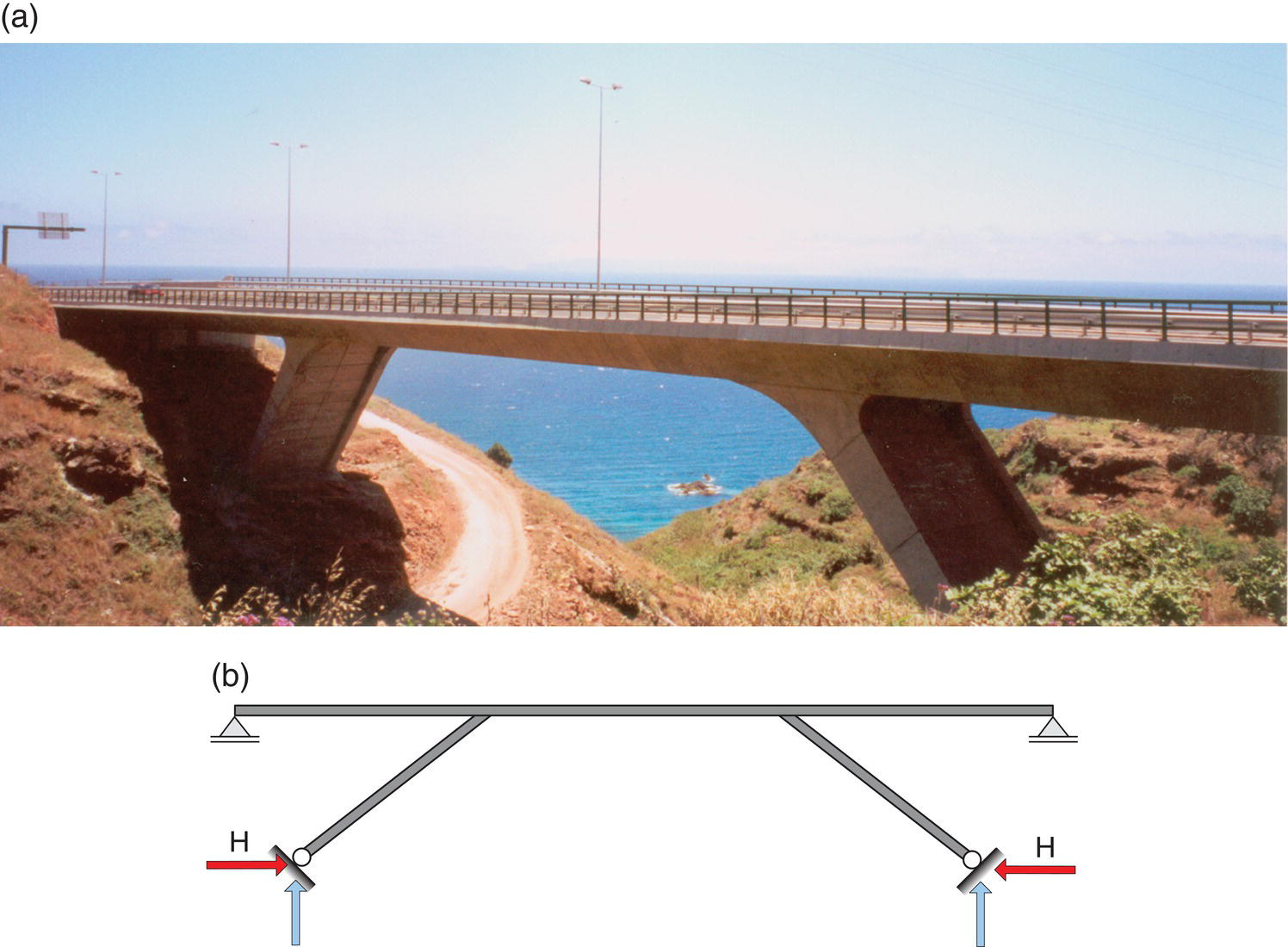
Figure 1.8 A frame bridge with inclined (slant) legs: (a) Reis Magos Bridge and (b) longitudinal structural model.
An arch is likely to be a very efficient type of structure, an aesthetically pleasant solution for long spans in deep valleys, provided the geological conditions are appropriate. The ideal shape of the arch, if the load transferred from the deck is considered as a uniformly distributed load q (valid for closed posts), is a second degree parabola because the arch for the permanent load is free from bending moments. In this case, the arch is only subjected to axial forces; that is, the arch follows the ‘pressure line’. It is easy to show using simple static equilibrium (bending moment condition equal to zero at the crown) that the thrust is given by ![]()
Arch bridges may have different typologies and be made of different structural materials. In the old days, masonry arches made of stones were very often adopted for small to medium span bridges. More recently, iron, steel and reinforced concrete bridges replaced these solutions with spans going up to several hundred metres. One of the most beautiful arch bridges is Arrábida Bridge, in Oporto (Figure 1.9), designed at the end of the 1950s, the beginning of the 1960s and opened to traffic in 1963. The bridge, at the time the longest reinforced concrete arch bridge in the world, has a span of 270 m and a rise of 54 m ( f/l = 1/5).

Figure 1.9 The Arrabida Bridge in Oporto, Portugal, 1963.
(Source: Photograph by Joseolgon / https://commons.wikimedia.org / Public Domain)
The arch bridge may have the deck working from above or from below, as shown in Figures 1.10 and 1.11. This last solution is adopted for traversing rivers at low levels above the water, with particular restrictions for the vertical clearance h for navigation channels. The horizontal component of the reaction at the base of the arch, at the connection between the arch and the deck, is taken by the deck. A bowstring arch bridge is the designation for this bridge type, in which the deck has a tie effect, together with its beam behaviour. Figure 1.12 shows a multiple bowstring arch bridge, with a continuous deck composed of a single steel box section. The deck, with spans of 160 m, is a steel‐concrete composite box girder to allow the required torsion resistance under eccentric traffic loading. However, the classical solution for bowstring arches is made of a beam and slab deck suspended from above by two vertical or inclined arches, as presented in Chapter 6.

Figure 1.10 Arch bridges: (a) the classical parabolic two hinges arch bridge; (b) structural longitudinal model; (c) independent arch and deck at the crown; (d) segmental arch and (e) low rise arch for a pedestrian bridge without posts.

Figure 1.11 A bowstring arch bridge: elevation and longitudinal structural model.

Figure 1.12 A bowstring arch for a railway bridge: (a) the crossing of the Sado River in Alcacer do Sal, Portugal, 2010 and (b) deck cross section – a steel concrete composite box girder.
(Source: Courtesy GRID, SA)
The main restriction nowadays for the construction of arches is the difficulty of the execution method, when compared to a long span frame bridge with vertical piers, built by the balanced cantilever method referred to in Chapter 4.
For spans above 150 m and up to 1000 m, cable‐stayed bridges, as previously shown in Figure 1.2, are nowadays generally preferred to beam or frame bridges, for which the longest span is about 300 m. Even for spans bellow 100 m, cable‐stayed bridges have been adopted as structurally efficient and aesthetically pleasant solutions; for example, in urban spaces where very slender decks are required. The basic schemes for the stay arrangement in cable‐stayed bridges are shown in Figure 1.13 – the fan, semi‐fan or harp arrangement. The semi‐fan arrangement is the most adopted one for economy of stay cable quantity. For aesthetics, usually the harp arrangement is the preferred one, since it reduces the visual impact of crossing cables for skew views of the bridge, as is apparent from Figure 1.2

Figure 1.13 Stay arrangements for cable‐stayed bridges: (a) fan, (b) semi‐fan and (c) harp systems.
In cable‐stayed bridges with spans up to 500 m the deck may be made of concrete, but above this span length, steel or steel‐concrete composite decks are preferred, to reduce the dead weight of the superstructure. The cable‐stayed bridge deck is subjected to large compressive forces induced by the stay cables, as shown in Figure 1.14. In the first generation of cable‐stayed bridges, the decks where in steel and the stay‐cable anchorages were kept at a considerable distance at the deck level. In these bridges, the beam load effect in the deck was relevant. In the last few decades, a new generation of cable‐stayed bridges has been developed with multiple stay cables anchored at small distances at the deck level, very often between 5 and 15 m, allowing a considerable reduction of the beam internal forces in the deck. This is the case for cable‐stayed bridges with very slender concrete decks with a span/height relationship for the deck that can reach very high values up to 400.

Figure 1.14 Cable‐stayed bridges: static equilibrium at deck level with axial forces induced by the stays.
In cable‐stayed bridges, the deck is supported by a single plan or two plans of stay cables. The former suspension scheme is designated axial or central suspension while the last one is called lateral suspension. The axial suspension scheme requires a deck with considerable torsion rigidity, generally a box girder deck, to support the asymmetric traffic loadings as well as to improve its aerodynamic stability. Figure 1.15 shows one of the most remarkable bridges built in 1977, at the time a world record for cable‐stayed bridges with a prestressed concrete deck. On the contrary, in lateral suspension cable‐stayed bridges, the deck may be reduced to a simple slab supported laterally by stay cables, or to a slab and girder section with an open configuration, since torsion resistance is assured by the staying scheme, as is the case for the Vasco da Gama Bridge (Figure 1.2b).

Figure 1.15 An example of a cable‐stayed bridge with axial suspension: (a) the Brotonne Bridge, France, 1977, with a main span of 320 m with (b) a concrete box girder deck cross section.
(Source: Photograph by Francis Cormon)
The other type of cable supported bridge is, as previously referred to, the suspension bridge. A suspension bridge includes a stiffening girder, the main cables, towers, hangers and anchoring blocks, as shown in Figure 1.16.

Figure 1.16 (a) Basic layout and notation of suspension bridges. (b) Externally anchored and self‐anchored suspension bridges.
The main cables are usually externally anchored (earth anchored cables), but in some bridges with smaller spans it is possible to adopt a self‐anchored suspension bridge by anchoring the cables at the deck, as shown in Figure 1.16. In the former, the tension forces are transferred directly to the ground while, in the latter, the cable forces are transferred (as large compression forces) to the deck.
The stiffening girder of a suspension bridge may be made of two parallel trusses, as the more classical suspension bridges developed in the North America during the twentieth century. A second generation of suspension bridges was introduced in Europe in the second part of the twentieth century, by replacing the truss‐stiffening girder by a streamline steel box girder deck and diagonal hanger ropes greatly improving the aerodynamic stability of the deck. In Figure 1.17, two of these bridge stiffening girder typologies are shown – the Akashi Kaikyō Bridge completed in 1998 in Japan, presently the world’s longest span at 1991 m, and the Great Belt East Bridge, also completed in 1998 but in Denmark, with a central span of 1624 m.

Figure 1.17 (a) Akashi Kaikyō Bridge, Japan, 1998, with a truss‐stiffening girder deck
(Source: Photograph by Pinqui/ https://commons.wikimedia.org)
and (b) Great Belt Bridge, Denmark, 1998, with a streamline box girder deck.
(Source: Photograph by Tone V. V. Rosbach Jensen/ https://commons.wikimedia.org)
In a suspension bridge, the permanent loads of the deck are taken by the cable system. The main cables adopt a parabolic configuration under the uniform dead load transmitted from the deck through the hangers. The live loads are basically taken by combined local bending action of the deck, between the hangers, and the main cable.
1.5 Some Historical References
The history of bridges is well‐documented in a variety of excellent references [1–4]. To keep this section within the scope envisaged for this book, a short historical review will present the roles of some architects, engineers and bridge builders.
Materials and structural shapes have always been the key elements to understand how bridges were conceived and built throughout the centuries. For bridge structural materials, one may considerer different stages grouped as follows:
- Stone/masonry and wood bridges;
- Metal–iron and steel bridges;
- Concrete reinforced concrete and prestressed concrete bridges.
The first group, stone/masonry and wood bridges, includes most of the bridge history from the Romans to the eighteenth century, while the second and third groups (metal and concrete bridges) may be included in bridge history from the eighteenth century to the present.
Structural shapes and static schemes were also key factors in bridge historical development that, in short, may be summarized as:
- Arch bridges;
- Beam, frame and truss bridges;
- Cable supported bridges – suspension and cable‐stayed bridges.
Contrary to what happens with bridge structural materials, it is not possible to include these structural typologies in different ages along bridge history. Even for cable supported bridges, one may find references to the use of ropes made with natural fibres to achieve a resistant structure in the early ages, even before the Roman Bridges. Nowadays, arches, introduced by the Romans, are made with different materials (concrete or steel), still reflecting the art of structural engineering.
1.5.1 Masonry Bridges
Apart from the earliest records of bridges, the first appears to be 600 BCE, engineering bridge history may be considered to have been initiated by the Romans. The Romans were the introducers of science in arch construction providing many examples of magnificent masonry bridges and aqueducts such as the ‘Pont du Gard’ in France and ‘Puente de Alcantara’ (Figure 1.18) over the river Tagus, Spain, from the second century [4]. The former is an aqueduct with a total length of 275 m, a maximum depth of 49 m and spans 22 m. The last is a masonry bridge as well, but with spans reaching 28 m and piles reaching 47 m high, appointed the most significant achievement of Roman engineering. Roman bridges are based on the concept of semi‐circular arches, transferring the thrust to piers, and large piers require about one‐third of the spans in multiple arch bridges. The Romans also introduced lime mortar and pozollanic cement for realizing voussoir arches, contributing to increasing span lengths and durability.

Figure 1.18 The Roman Alcantara Bridge in Spain, second century.
(Source: Photography by Dantla/ https://commons.wikimedia.org)
Up until the end of the eighteenth century, bridges were built with masonry or wood. Some beautiful examples built along the centuries may still be appreciated, such as Santa Trinita Bridge in Florence (Figure 1.19) built with masonry in the sixteenth century and designed by the architect Bartolomeo Ammanati. While the classical Roman Bridges were made with circular arches, the elegance of Santa Trinita Bridge is due to three flattened elliptic arches, which are the oldest in the world. At the beginning of the twentieth century, in 1905 to be precise, the span record for masonry bridges was reached with the construction of the Plauen Bridge [1, 3], in Germany, which has a main span of 90 m.

Figure 1.19 Santa Trinita Bridge in Florence, sixteenth century.
(Source: Photography by Bruno Barral/ https://commons.wikimedia.org)
1.5.2 Timber Bridges
In the eighteenth century, some remarkable wood bridges were built. In Switzerland, due to a long tradition of wood construction builders, remarkable structures were built, like the Shaffhouse Bridge, designed in 1775 by Grubleman, with two continuous spans of 52 and 59 m. In the USA, one of the most famous wood bridges was built in 1812, over the river Schuylkill with a main span of 104 m, unfortunately destroyed by a fire some years after its construction. Most old timber bridges have disappeared along history; an exception, presently the oldest wooden bridge to our knowledge, is the Kappellbruke (Chapel Bridge) erected originally in 1333 over Lake Lucerne, Switzerland (Figure 1.20). This footbridge was also destroyed by a fire in 1993 and completely rebuilt, standing now as a world heritage site.

Figure 1.20 Chapel Bridge, Lucerne, Switzerland, 1333 (rebuilt after fire in 1993).
(Source: Photograph by José O. Pedro)
1.5.3 Metal Bridges
With the Industrial Revolution of the nineteenth century, metal structures became more and more competitive and, finally, iron and steel started to be used as bridge materials. From this time on, metal truss bridges and suspension bridges were adopted with increasing span lengths.
The first metallic bridge built in the world may be considered to be the Coalbrookdale Bridge [4] with a span of 30 m, designed by Abraham Darby III, a cast iron structure built in Great Britain in 1779. But development had to wait until the end of the nineteenth century, when the prices for steel production has dropped down, to realize the first main steel bridges. One of the most decisive contributions for the development of metal bridges was from Thomas Telford in the nineteenth century. Telford was an English engineer with a large number of relevant projects, always taking aesthetics as a key issue for his work, in parallel with the development of new structural and construction schemes. Craigelachie Bridge, in Scotland, shown in Figure 1.21, is an excellent example of the aesthetical relevance of Telford's design work. In 1826, a famous eye bar wrought iron chain suspension bridge (Figure 1.22), with a main span of 176 m, also from Thomas Telford, was completed in the UK over the Menai Strait, achieving the world record for span length. The iron chain was replaced in 1938 by pin steel bars, allowing the bridge to remain in service up until now. The construction of long span beam bridges is considered to have been initiated with the first box girder bridge in wrought iron, the Britannia Bridge in Wales, UK, built in 1850 by Robert Stephenson (Figure 1.23). The Britannia Bridge, with two main spans of 146 m, had a rectangular cross section with a railroad inside. After a fire in 1970, this famous bridge was modified in 1971 by inserting a truss arch underneath and carrying road and rail traffic, but seriously affecting the architecture of the bridge. The type of box girder solution adopted for the Britannia Bridge was not retained due to the development of truss arch bridges at the end of the nineteenth century.

Figure 1.21 Craigellachie Bridge, 45 m span, over the Spey River, Scotland, 1815.
(Source: Photograph by Craig Williams/ https://commons.wikimedia.org)

Figure 1.22 Menai Suspension Bridge, 1826, Wales.
(Source: Photography by Bencherlite/ https://commons.wikimedia.org)

Figure 1.23 The Britannia Bridge, 1850, North Wales.
(Source: Courtesy of the Los Angeles County Museum of Art)
Reductions in steel prices allowed the increased development of steel arch bridges, or more precisely, wrought iron, with particular reference to long span bridges in the USA. The most famous one was the San Luis Bridge, over the Mississippi, concluded in 1874 with three arches of 152 + 157 + 152 m, and in Europe with several famous arch bridges from the Gustave Eiffel Society. The first relevant Eiffel's bridges were the Maria Pia Bridge in Oporto, Portugal [5], in 1877, and the Viaduc du Gabarit, in France, in 1884. The former (Figure 1.24) 563 m long and with a main span of 160 m, has a truss arch for the railway deck of only 6 m. Particular reference should be made to the erection scheme of the arch using cantilever construction. The Viaduct du Gabarit has a main span arch of 165 m, 52 m rise and a total length of 564 m. This arch was also erected by cantilever as per the Maria Pia Bridge. In 1885, the Belgium engineer Théophile Seyrig, who had worked with Eiffel, designed the Luiz I Bridge [6], also in Oporto and very close to the Maria Pia Bridge. The Luiz I Bridge, an arch bridge, was the largest span in the world at its time – 174.5 m (Figure 1.25a). This bridge with two road decks has a two hinged arch at the base, in spite of its appearance, due to the need of inserting the lower deck. The bridge is located in a classified UNESCO World Heritage Site. A great deal of strengthening of the bridge was done in 2005 (Figure 1.25b), including its arch, truss girder and piers, with an entire replacement of the upper deck with a new steel deck, adapting it for the Metro of Oporto trains (Figure 1.26). The reduction in dead weight of the existing deck, which included concrete and brick elements inserted many years after the original deck, was achieved. The reductions in deck dead load allowed a significant reduction in the strengthening of the arch required for the new functional conditions and required strengthening of the bridge. The design of the upgrading of the bridge was made without affecting its appearance as required by the design and build conditions of the bid.

Figure 1.24 Maria Pia Bridge, 1877, Oporto, Portugal.
(Source: Photograph by José O. Pedro)

Figure 1.25 (a) Luiz I Bridge, 1885, Oporto, Portugal: (a) before and (b) during the upgrading works.
(Source: Courtesy GRID, SA)

Figure 1.26 Luiz I Bridge after being upgraded.
(Source: Photograph by José Araujo)
With the development of industrial production of steel, after the introduction by Henry Bessemer in 1856 of its patent, the Bessemer Converter, transforming cast iron in to the much better steel material, in terms of tensile resistance and ductility, allowed the building of long span trusses in the United States and Europe. The first long span European bridge was the Firth of Forth Bridge (Figure 1.27) built between 1881 and 1890, with two main spans of 521 m and two side spans of 207 m. The two main spans were made with two cantilevers of 207 m supporting a central part made of truss beam 107 m in length. The development of these types of bridges was not unfortunately made without the occurrence of some historical accidents, such as the one occurring in the railway bridge over the river Tay, Scotland, in 1879 and the accident during the erection of the Quebec Bridge, Canada, in 1907. The Quebec Bridge with spans of 549 m was concluded only after a second accident during construction in 1917.

Figure 1.27 Firth of Forth Bridge, 1890, Scotland.
(Source: Photograph by Andrew Shiva/Godot13, https://commons.wikimedia.org/wiki/File:Scotland‐2016‐Aerial‐Edinburgh‐Forth_Bridge.jpg. CC BY‐SA 4.0)
1.5.4 Reinforced and Prestressed Concrete Bridges
The lack of sufficient tensile resistance makes concrete inadequate as a bridge structural material. However, concrete offers the advantage of being a plastic material in the sense that it is poured like fluid in a mould before it hardens, allowing a variety of shapes for beams and piers that could not be achieved in a simple way with steel materials and steel profiles. Some arch bridges with relevant spans, using mass concrete, were made at beginning of the twentieth century, such as the Willeneuve – Sur‐Lot Bridge, in 1919, with an arch span of 97 m, by Eugéne Freyssinet. François Hennebique was one of the first to understand the role of steel reinforcement in concrete to create a suitable bridge material. In 1911, he ‘made’ (Hennebique was more a builder than a designer) the Risorgimento Bridge in Rome, achieving a 100 m span, but the development of reinforced concrete bridges occurred with the work of the great Swiss engineer Robert Maillart who was the first to explore the potentialities of reinforced concrete to build magnificent arch bridges. He explored the concept of relative stiffness between the arch and the deck structure, introducing the concept of Maillart's arch, an arch without bending stiffness, achieved by reducing the stiffness in such a way that the arch follows the pressure line working only under normal forces. However, its thickness is enough to resist to arch buckling. The arch works in this case as the opposite of a cable in a suspension bridge. Among the bridges based on Maillart's arch concept, the longest arch span, 43 m, was the one of the Tshiel Bridge built in 1925. Robert Maillart explored a variety of arch structures from built‐in arches to three‐hinged arches, such as those he adopted for his classical bridge, the Salginatobel Bridge, in Switzerland (Figure 1.28), built in 1930 with a 90 m span. In 1901, Maillart was also the first to adopt a concrete box section for arches, in the Zuoz Bridge with a 30 m span structure. At the beginning, concrete arch bridges were always associated with large wood scaffolding structures, some of them initially developed by R. Coray, built by cantilever construction from each side until the closure at the mid‐section was reached. One may even say the most relevant wood bridges in the world were the scaffolding of concrete arch bridges. A detailed discussion on the historical development of scaffolding structures is presented in the excellent book by Troyano [4].

Figure 1.28 The Salginatobel Bridge, 1930, Switzerland.
(Source: Photograph by Rama, https://commons.wikimedia.org/wiki/File:Salginatobel_Bridge_mg_4077.jpg. CC BY‐SA 2.0 FR)
The concept of multiple arch bridges in reinforced concrete was adopted by Eugéne Freyssinet in 1930, in Plougastel Bridge. This bridge, over the river Elorn in France, is made with three arches of a 186 m span each, following the concepts of previously built multiple arch metal bridges. Many years before, in 1910, Freyssinet designed a beautiful multiple three arch bridge with very flat arches and a rise‐span ratio of only 1/14.7. The arches, each with a 77.5 m span, were initially built as three hinged arches but a few months after completion Freyssinet detected alarming increased deflections at the mid‐span sections due to creep effects in the concrete. He decided to recover the initial shape of the bridge by inserting jacks at the mid span hinge sections and to eliminate these hinges. The beauty of the bridge was the result of the flatness of the arches but also due to the triangulated system adopted to transfer the loads from the deck to the arches. Unfortunately, this bridge was destroyed during the Second World War.
The span lengths of concrete arch bridges were increasing, and one of the largest spans is still the 390 m long arch of the Krk Bridge (Figure 1.29), completed in 1979 in the former Yugoslavia.

Figure 1.29 The Krk reinforced concrete arch bridge, 1979, former Yugoslavia.
(Source: Photograph by Zoran Knez/ https://commons.wikimedia.org)
Since the end of nineteenth century, the idea of prestressing was always present as a potential scheme to induce initial compressive stresses in concrete and therefore to improve its lack of resistance under tensile stresses. However, it was only in 1928 that Freyssinet decided to concentrate all his activities to explore the potentialities of prestressing for concrete structures. The difficult experience he had with time dependent deformations of concrete in the Veudre Bridge has shown the influence in concrete. Freyssinet understood the need to adopt high strength steel for prestressing and he develop specific systems to anchor prestressing wires or steel bars.
The first long span bridge made in prestressed concrete was the Luzancy Bridge (Figure 1.30) in France, over the river Marne, with a span of 55 m and concluded in 1946. The bridge has been entirely precast in prestressed segmental construction and erected by mechanical devices without any scaffolding. The development of prestressed concrete bridges was very fast in the second half of the twentieth century. Apart from the use of prestressing for prescasting beams, developed in France after the pioneering works of Freyssinet, a special reference should be made to the German contributions in the reconstruction of many bridges after the Second World War. Most of the progress in this field was due to the development of new construction schemes based on the potentialities brought by the prestressing technique in concrete bridges. To achieve large spans avoiding any scaffolding, the idea of cantilever construction of concrete bridges was developed in Germany by Finsterwalder. In 1950, he designed the Balduintein Bridge over the Lahn River with a span of 62 m. It should be noted the cantilever system, a construction scheme adopted since 1874 for steel bridges, was adopted by the first time in concrete bridges for the construction of the bridge over the river Peixe, completed in 1931 in Brazil, with a main span of 68.5 m. The balanced cantilever scheme, in which the bridge is built by cast in‐place segmental construction for each side of each pier allowing for large spans to be reached using simple and small steel equipment, opened a new field in bridge construction technology. The spans quickly increased passing from more than 100 m to reach the main spans of 250 m in several road bridges nowadays. The longest span in full prestressed concrete built by cantilever construction is 301 m in the Stolmasundet Bridge [7], concluded in Norway in 1998. This bridge adopted lightweight concrete in the middle section of the main span to reduce dead weight. Other relevant long span road bridges are the Gateway Bridge in Australia, built in 1985, and the Varodd Bridge in Norway, both with 260 m main spans. In railway bridges, the longest span is the São João Bridge [8], in Oporto, Portugal, a design due to Edgar Cardoso, with a span of 250 m, completed in 1991 (Figure 1.31).

Figure 1.30 The Luzancy Bridge, 1946, France.
(Source: Photograph by MOSSOT, https://commons.wikimedia.org/wiki/File:Pont_de_Luzancy_‐1.JPG. CC BY‐SA 3.0)

Figure 1.31 The São João Railway Bridge, 1990, Oporto, Portugal.
(Source: Photograph by Joseolgon/ https://commons.wikimedia.org / Public Domain)
Precasted segmental construction was also a relevant contribution to the development of prestressed concrete bridges, either made by balanced cantilever or with moving scaffoldings to erect the segments. The first bridge with this construction technology was made in 1966 for the Oleron Bridge in France, a long bridge (2900 m) connecting the continent to the island of Oleron, with typical spans of 79 m.
1.5.5 Cable Supported Bridges
Suspension bridges were adopted in the early days of bridge history, namely in pedestrian bridges with natural fibres for the cables. The suspension system was made by a chain of eye bars in cast and wrought iron, already previously referred to with respect to the Menai suspension bridge. But it was the early wire suspension system, adopting wrought iron and strand spinning technology due to John Roebling [9], which gave rise to a new generation of suspension bridges. In 1883, the Brooklyn Bridge, designed by Roebling with a span of 487 m and built in New York, was the first steel wire suspension bridge in the world. At the beginning of the twentieth century, a variety of long span suspension bridges were built in USA. In 1931, George Washington Bridge, designed by the Swiss O. Ammann over the Hudson River in New York, used parallel wire strands rather than rope strand cables and reached a span longer than 1000 m for the first time. This bridge, with a 1067 m main span, doubled the longest existing span but retained this record for only six years when the famous Golden Gate Bridge [9], San Francisco, designed by Joseph Strauss, concluded with a main span of 1280 m.
Contrary to the robustness appearance of the existing suspension bridges at that time, the Tacoma Narrows Bridge was built in 1940, in the state of Washington, with a much slender deck than the typical ones adopted at the time. The main difference was the slender plate girder deck adopted for its superstructure. After a few months in service, the bridge collapsed because of aerodynamic instability under wind action with a much lower wind speed than the one adopted in its design. Aerodynamic phenomena were known at the time by aeronautical engineers but not by bridge engineers. The bridge was rebuilt with a deep stiffening truss deck in 1950. Many of the existing suspension bridges at the time had been strengthened and all new ones built since the Tacoma Bridge accident have been subjected to detailed aerodynamic studies.
While the US suspension bridge concepts have kept the rigid truss superstructure, the European evolution, mainly due to English engineers, tends towards the use of streamline bridge decks for aerodynamic stability. The Severn Bridge, concluded in 1966, with a main span of 988 m, was the first achievement, eliminating the need to adopt the deep stiffening truss decks. The Tagus River Bridge was opened to traffic in 1966 using a typical rigid truss girder designed by Steinman, New York. The design considered, according to the bid specifications, the possibility of a railroad addition at the lower chord level. With a 1013 m main span, it was, at the time, the longest span in Europe. Thirty years later, the railroad addition was implemented with a completely different concept for this stage than initially foreseen. The trains crossing the bridge nowadays are about 2.5 times heavier than the ones initially foreseen. In the original design, the additional loads due to the railroad were foreseen to be supported by a set stay cables; when the project was implemented, a second cable was added and one new hanger between each of two existing ones was inserted.
In 1981, the Humber Bridge was concluded in the UK. With the longest 1410 m main span at the time, a streamline box girder deck was used as was for the Severn Bridge, but adopting a triangular suspension system for the hangers. It kept the span world record for years until the Great Belt Bridge, 1624 m, and the Akashi Kaikyō, 1991 m, were built in 1998; referred to in Section.
In the second half of the twentieth century, a new generation of cable supported bridges was developed: cable‐stayed bridges. The Strömsund Bridge, concluded in Sweden in 1955, was one of the first cable‐stayed bridges, followed some years later by the three bridges in Dusseldorf, Germany; the North Bridge (260 m span) with two towers and the Knie and Oberkassel Bridges each with a single tower and spans of 320 m and 258 m, respectively [1]. All three Dusseldorf bridges, over the Rhine River, adopted steel decks suspended by stay cables with a harp arrangement and spaced about 30 m at the deck level. Following these bridges, a variety of longitudinal configurations and deck cross sections have been implemented for this bridge typology. However, the most important innovation was the introduction of closed spaced stay cables at the deck level (5–10 m in concrete bridge decks and about 12–20 m in steel decks), allowing the deck to work as a beam on elastic foundations with small bending moments.
At the end of the 1980s in the twentieth century, maximum spans increased, in particular with Annacis Bridge in Vancouver, Canada [10], with a main span of 465 m with a steel‐concrete composite deck. A large step was achieved with the construction of the Normandy Bridge, in France in 1995, following a concept design from Michel Virlogeux [11]. With a main span of 856 m, this bridge adopted a steel box girder deck in the central part (624 m) of the main span continued to the towers and lateral spans with a prestressed concrete box girder deck. The 1000 m span length for cable‐stayed bridges was first reached by two bridges. The first, the Stonecutters’ Bridge concluded in 2009 in Hong Kong, with a 1018 m steel main span, and short 299 m lateral concrete spans [12]. This bridge introduced the option of splitting the deck cross section in to two separate boxes for aerodynamic stability.
The longest span length for cable‐stayed bridges is presently the second, the Russky Bridge, built across the Eastern Bosphorus strait in Vladivostok in 2012, adopting a single box girder deck with a main span of 1104 m and lateral stay cable suspension, as in all other very long cable‐stayed bridges [13].
The increased development of cable supported bridges, either suspension bridges or cable‐stayed bridges, will continue in the coming years. Suspended spans above 3000 m, like the one considered in the design of the Messina Bridge [14], may be achieved in the near future.
Even if span length is often taken as key parameter to evaluate historical bridge evolution, one should take into consideration that many other aspects and solutions had decisive contributions to the development of bridge design throughout history. Even considering only cable supported bridges, a variety of bridge innovative solutions may be referred to as:
References
- 1 Leohnardt, F. (1982). Bridges – Aesthetics and Design, 308. London: The Architectural Press Ltd.
- 2 Wittfoht, H. (1984). Building Bridges – History, Technology, Construction, 327. Beton Verlag GmbH.
- 3 Menn, C. (1990). Prestressed Concrete Bridges, 536. Springer.
- 4 Troyano, L.F. (2003). Bridge Engineering: A Global Perspective, 775. Thomas Telford.
- 5 Ordem dos Engenheiros – Região Norte (2005). Ponte Maria Pia – A obra‐prima de Seyrig 150 pp.
- 6 Reis, A., Lopes, N., and Ribeiro, D. (2007). The new metro of Oporto: a variety of bridge projects. IABSE Symposium Report 93 (13): 18–25.
- 7 Tang, M.‐C. (2007). Evolution of bridge technology. IABSE Symposium Report 93 (31): 38–48.
- 8 Lousada Soares, L. (2003). Edgar Cardoso: Engenheiro Civil, 370. FEUP.
- 9 Gimsing, N.J. and Georgakis, C. (2012). Cable Supported Bridges – Concept and Design, 3e, 590. Wiley.
- 10 Taylor, P. and Torrejon, J. (1987). Annacis Bridge. Concrete International 9 (7): 13–22.
- 11 Virlogeux, M. (1994). The Normandie Bridge, France: a new record for cable‐stayed bridges. Structural Engineering International 4 (4): 208–213.
- 12 Falbe‐Hansen, K., Hauge, L., and Kite, S. (2004). Stonecutters Bridge – detailed design. IABSE Symposium Report 88 (6): 19–24.
- 13 Svensson, H. (2012). Cable‐Stayed Bridges – 40 Years of Experience, 430. Wilhelm Ernst & Sohn, Germany.
- 14 Brown, D.J. (1993). Bridges – Three Thousand Years of Defying Nature, 176. Mitchell Beazley.
- 15 Virlogeux, M., Servant, C., Cremer, J.M. et al. (2005). Millau Viaduct, France. Structural Engineering International 15 (1): 4–7.
- 16 Teyssandier, J‐P. (1997). The Rion‐Antirion Bridge. Proceedings of the FIP International Conference, Vol. 2, 1163–1170.
- 17 Klein, J.F. (2017). Third Bosphorus Bridge – a masterpiece of sculptural engineering. Stahlbau 86 (2): 160–166.