
9 Control and limitation of high short-circuit currents
9.1 General
Many power system networks can be subject to high potential short-circuit fault currents. Some of the reasons for this include the connection of new generation plant to transmission and distribution networks, the strengthening of the power networks by the addition of new parallel routes, the use of low impedance equipment to improve voltage and reactive power control and system transient stability, the connection of many induction motors in industrial networks, and others. In this chapter, we describe some of the practical methods and techniques that may be used for the control and limitation of the magnitude of short-circuit currents in both power system operational and design timescales. Various types of established and emerging state of the art short-circuit fault current limiters that may be used to control and limit fault currents to safe values as well as their modelling techniques will be described.
9.2 Limitation of short-circuit currents in power system operation
9.2.1 Background
Depending on national or even particular utility practices, power system operation may extend from real time up to typically 6 months to 2 years ahead. The objectives are to ensure that the power system is operated in a safe, secure, reliable and economic manner, whilst planned maintenance and construction outages can be carried out as necessary. In both real time and operational planning timescales, the only measures that are usually available to control and limit the magnitudes of potential short-circuit currents are those that utilise existing equipment in the existing system. Some of these measures are described in the next sections.
9.2.2 Re-certification of existing plant short-circuit rating
This method may be used when a short-circuit current duty is predicted to be in excess of the nominally declared short-circuit capability of the circuit-breaker or substation infrastructure equipment. The method consists of re-examination of existing equipment’s test certificates for any additional inherent capability that may be available over and above that specified in initial tender documents. If found available, this additional capability is usually re-certified with the equipment manufacturer before being released for use.
9.2.3 Substation splitting and use of circuit-breaker autoclosing
For substations that are normally run solid, and where potentially excessive short-circuit currents are predicted, the substation may be split in order to reduce the short-circuit currents for faults on either side of the split. The reduction is caused by the increase of the effective impedance between the fault location and some of the short-circuit current sources in the system. Substation splitting, in its simplest form, in single- and double-busbar substations, is accomplished by opening bus section or bus coupler circuit-breakers and operating them in a normally open position as shown in Figure 9.1.

Figure 9.1 Substation splitting for short-circuit current limitation: (a) Single-busbar substations, bus section breaker normally open (N/O), (b) vertical split in double-busbar substations and (c) horizontal split in double-busbar substations
Unfortunately, substation splitting reduces the degree of interconnectivity of the substation and in some cases may equate, electrically, to the removal of circuit(s) out of service. The reduction in reliability is illustrated in Figure 9.1(a) in the case of a single-busbar transformer fed substation as may be found in typical distribution systems. A fault outage on transformer T1 results in the loss of supply to busbar section 1 and all demand supplied from the distribution feeders connected to it.
Since the operation of the three transformers in parallel causes excessive short-circuit currents in the single-busbar substation, it is required to improve the security of supply to busbar section 1 and limit the potential short-circuit currents to within circuit-breaker ratings. These objectives may be met by using one of the schemes shown in Figure 9.2.

Figure 9.2 Use of autoclose schemes in short-circuit current limitation: (a) normally open bus section circuit-breaker with autoclosing and (b) normally open breaker of a hot standby transformer with autoclosing
In Figure 9.2(a), the bus section circuit-breaker is normally run open with an autoclosing facility so that fault current so neither busbar sections are safely limited. In the event of loss of transformer T1, the normally open bus section circuit-breaker is automatically closed so that transformers T2 and T3 supply the entire substation load. Sometimes autotripping may also be used in order to automatically reopen the bus section breaker when T1 is returned to service. Figure 9.2(b) shows an alternative arrangement where the bus section circuit-breaker is run normally closed and either T2 or T3 is operated on hot standby. This means that the transformer is permanently energised from its primary but its secondary breaker is normally run open with an autoclosing facility. This breaker is automatically closed in the event of loss of transformer T1 to prevent overloading of transformer T2. Autotripping may also be used.
The principle of substation splitting can also be applied in industrial power systems where generally single-busbar substations are used and these are interconnected by busbar sectionalisers which may be a cable circuit controlled by two circuit-breakers. In this case, one of these circuit-breakers is normally operated open.
9.2.4 Network splitting and reduced system parallelism
Transmission systems operating at different voltage levels, e.g. 400 and 275 kV (or 220 kV), are normally operated in parallel. In addition, distribution systems operating at, say, 132 or 110 kV may in some cases be operated in parallel with transmission systems. The latter is illustrated in Figure 9.3 where the 132 kV distribution system is supplied from two substations that may be many kilo-metres apart from each other and the entire distribution system is normally operated interconnected.

Figure 9.3 Illustration of subtransmission/distribution network splitting for short-circuit current control
Sources of short-circuit currents in the transmission and distribution systems can contribute to faults at substations A or B. However, if the interconnected distribution network is split by operating circuit-breakers CB1 and CB2 normally open, the short-circuit sources in distribution subnetwork A become electrically remote from faults at substation B and vice versa. The magnitude of short-circuit current reduction depends on the specific characteristics of the distribution system, e.g. the degree of interconnection and amount of connected generation plant as well as the relative proportions of currents supplied from the transmission and distribution systems. In general, reductions of up to 30% might be obtained. As in Section 9.2.3, it should be noted that the interconnection is planned in the first place to increase the reliability of the distribution network and the effect of network splitting on demand security would need to be considered. Although more difficult in this case, autoclosing may also be considered as discussed in Section 9.2.3.
9.2.5 Sequential disconnection of healthy then faulted equipment
This method of short-circuit current limitation is only suitable when the circuit-breaker breaking or interruption duty is the limit rather than the making duty which is within equipment rating. The method is illustrated using Figure 9.4.

Consider a short-circuit fault on the line side of circuit-breaker F that results in a short-circuit current that exceeds the rating of circuit-breaker F. All other circuit-breakers in the substation may also be overstressed. The short-circuit breaking current at F with the remote circuit-breaker Fr open is given by IF = Σ4j=1 Ij. In this method of current limitation, another upstream circuit-breaker feeding the short-circuit fault, e.g. CB1, is opened first then circuit-breaker F is opened to safely interrupt the reduced short-circuit current. This method can introduce significant disadvantages and risks to the reliability and safety of power systems and these have to be thoroughly evaluated. The fault clearance time is delayed by the upstream breaker operation time. Also, a fault at F would normally constitute a (N − 1) condition but in this method, another healthy circuit is deliberately disconnected giving a (N − 2) contingency. The term (N − x) represents the total system N less x circuits. Where automatic circuit reclosure on the faulted circuit is not employed, i.e. circuit-breaker F will not reclose after clearing the fault, circuit-breaker CB1 can be reclosed immediately once circuit-breaker F has opened and cleared the fault. However, if automatic reclosure is employed, then the decision to reclose CB1 should consider the two possibilities of the fault being transient or permanent. In practice, the engineering of such schemes may be very complex. In addition, from a safety point of view, in-service breaker F is potentially overstressed, but its safe operation is dependent on the success of a sequential tripping scheme that must ensure the opening of breaker CB1 first. If for some reason this scheme fails, there may be significant adverse system reliability and safety consequences.
9.2.6 Increasing short-circuit fault clearance time
This method consists of delaying the current interruption time of the circuit-breaker from, say, 50 to 100 ms. The delay is used in order to benefit from the decrease with time of both the ac and the dc components of the short-circuit current. However, the effect of any delay in the fault clearance time on the stability of the power system will need to be considered. The method depends on national practice in terms of the standard used for the calculation of short-circuit currents since some ignore the decay of short-circuit currents with time altogether.
9.2.7 De-loading circuits
This method of fault current limitation consists of opening one circuit-breaker at one end of a circuit but keeping the circuit energised from the other end(s) in order to benefit from its reactive power gain generated by its susceptance. The opened circuit-breaker is operated normally open to reduce the short-circuit infeed into the substation. An autoclose arrangement may be used in the event of a loss of another infeeding circuit into the substation. The method is conceptually similar to operating transformers on hot standby with autoclosing as described in Section 9.2.3.
9.2.8 Last resort generation disconnection
In real-time system operation, the disconnection of generation plant that can feed short-circuit currents into a local substation for fault current limitation is highly unusual. Such action can be very costly in liberalised electricity markets so that even if the disconnection is required only once and for a few hours, the costs that may be incurred may be similar to or exceed the cost of purchasing and installing a new extra high voltage circuit-breaker. Some of the other techniques already described are examined first and usually the splitting of the substation or the de-loading of one feeder circuit may be used.
9.2.9 Example
Example 9.1
Figure 9.5 shows a 400 kV transmission substation supplying a 132 kV substation through four 240 MVA 400 kV/132 kV autotransformers.
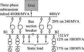
The 132 kV substation is of a double-busbar design and the 132 kV network is radial. Three 100 MVA generators are connected to the 132 kV busbar as shown. The 132 kV circuit-breakers and substation infrastructure three-phase short-circuit rating is 5000 MA corresponding to 21.9 kA three-phase short-circuit current. Calculate the 132 kV three-phase busbar short-circuit current when the 132 kV substation is operated solid and split using the busbar section circuit-breaker. For quicker hand calculation, all network resistances are ignored and the 132 kV feeders are assumed to supply a static load only. The generator’s subtransient reactances are given. The initial ac currents are to be calculated.
Solution
The positive phase sequence (PPS) subtransient reactance of the system infeed on a 100 MVA base is calculated as
The autotransformer PPS reactance on a 100 MVA base is equal to
The Thévenin’s equivalent impedance ‘seen’ at the faulted 132 kV busbar is calculated as
The 132 kV busbar three-phase fault level is equal to 100 MVA/0.0188 pu = 5319 MVA and this corresponds to a three-phase fault current of 5319 MVA/![]() which exceeds the 21.9 kA rating. Clearly, the bus section and feeder circuit-breakers are all potentially overstressed. Also, the generator-transformer breakers are overstressed for a fault on the transformer side of the breaker since each generator contribution to the fault is equal to 1.5 kA. The reader is encouraged to show that the 132 kV breakers of the autotransformers are not overstressed since the fault current for a fault on the transformer side with the 400 kV breaker open is only 19 kA. It is noted that under the busbar fault condition, the current supplied through each autotransformer is 4.7 kA, but the duty on the autotransformer 132 kV breaker is not equal to 23.3 kA–4.7 kA = 18.6 kA!
which exceeds the 21.9 kA rating. Clearly, the bus section and feeder circuit-breakers are all potentially overstressed. Also, the generator-transformer breakers are overstressed for a fault on the transformer side of the breaker since each generator contribution to the fault is equal to 1.5 kA. The reader is encouraged to show that the 132 kV breakers of the autotransformers are not overstressed since the fault current for a fault on the transformer side with the 400 kV breaker open is only 19 kA. It is noted that under the busbar fault condition, the current supplied through each autotransformer is 4.7 kA, but the duty on the autotransformer 132 kV breaker is not equal to 23.3 kA–4.7 kA = 18.6 kA!
132 kV substation split with bus section breaker normally open
The Thévenin’s equivalent impedance ‘seen’ at the fault point for a fault on busbar section B1 is calculated as

The 132 kV busbar three-phase fault level is given by XThév. = 100 MVA/0.03386 pu = 2953 MVA and this corresponds to a three-phase fault current of 2953 MVA/![]() ) which is substantially less than the 21.9 kA rating. The three-phase fault current at busbar B2 is equal to 11.4 kA. Therefore, the short-circuit current duties are well within the ratings of all 132 kV circuit-breakers.
) which is substantially less than the 21.9 kA rating. The three-phase fault current at busbar B2 is equal to 11.4 kA. Therefore, the short-circuit current duties are well within the ratings of all 132 kV circuit-breakers.
This huge reduction in short-circuit current magnitude is due to the assumption that the 132 kV network emanating from the 132 kV substation is radial. Where this network is interconnected, an equivalent interconnecting impedance would still exist between the two 132 kV busbar sections when the 132 kV busbar is split. The effect of this is that the reduction in the magnitude of short-circuit current may be significantly reduced.
9.3 Limitation of short-circuit currents in power system design and planning
9.3.1 Background
Depending on national or even particular utility practices, power system design and planning may extend from typically 6 months ahead up to 7 years ahead or more. The objectives are generally to design the connection of new generation plant and demand centres to the existing network as well as the network infrastructure reinforcements required to ensure secure and reliable power system into the future. In future network planning and design timescales, many competing measures are available to the designer to secure the network and ensure safe short-circuit fault level management including the planning and engineering of the installation of new equipment.
In general, some of the methods described in Section 9.2 can also be used at the network design stage, e.g. re-certification of existing plant short-circuit capability, substation splitting and use of circuit-breaker autoclosing, network splitting and reduced system parallelism, increasing circuit-breaker fault clearance time and de-loading of circuits. In the next sections, we will describe some of the additional measures generally available to the system design engineer.
9.3.2 Opening of unloaded delta-connected transformer tertiary windings
Many transformers used in power systems have an additional unloaded third or tertiary winding. As we discussed in Chapter 4, the delta tertiary winding presents a low zero phase sequence (ZPS) impedance path to the flow of ZPS currents. Therefore, when opened, no ZPS current can circulate inside the winding. This has the effect of increasing the shunt ZPS impedance to earth to a very large value depending on the transformer core construction. This increase is greatest for 5-limb and shell-type core transformers. However, experience shows that the overall effect on the reduction of the magnitude of single-phase to earth short-circuit current is relatively small and local and hence this technique, which is very attractive economically, is potentially useful in marginal overstressing at specific locations. The delta tertiary winding also provides a path for the circulation of third harmonic currents which arise mainly from the transformer magnetising current. The opening of the delta winding causes third harmonic ZPS currents to circulate further into the system which may cause unacceptable voltages and interference in communication networks. Therefore, the use of this technique requires careful consideration.
9.3.3 Specifying higher leakage impedance for new transformers
A short-circuit overstressing problem may be caused when a substation is being reinforced through the addition of one or more new transformers. The short-circuit currents fed through the transformers to the fault location can be reduced by specifying higher than average transformer leakage impedance, e.g. by up to 40% or 50%. However, the increased transformer impedance causes an increase in the transformer reactive power losses and voltage drop and hence the provision of the required supply voltage quality may require a tap-changer to have a wider tapping range. Nonetheless, appreciable reduction in the magnitude of short-circuit current may be obtained.
9.3.4 Upgrading to higher nominal system voltage levels
The short-circuit current magnitude in kA for a given short-circuit fault level in MVA is inversely proportional to the nominal system voltage level. In most practical situations, however, electrical power systems and their voltage levels already exist and the construction of higher voltage systems for short-circuit limitations only may not be economically justifiable. To illustrate the effect on the short-circuit current magnitude of connecting a power station unit (a generator and its step-up transformer) at two different voltage levels, consider a 100 MVA generator having a 20% subtransient reactance and a step-up transformer having a 15% leakage reactance, both on 100 MVA. With the generator unloaded and a 1 pu pre-fault voltage, the initial magnitude of the short-circuit current for a three-phase short-circuit fault on the transformer’s high voltage side is equal to
Therefore, the magnitude of the short-circuit current delivered from the power station unit will be equal to 1.25 and 0.75 kA for connecting to 132 and 220 kV systems, respectively. In practice, the reduction in short-circuit current for connecting to 220 kV will be a little higher because the transformer’s leakage reactance increases with winding voltage. In general, the benefits of such reductions will need to be balanced against the increased costs of connecting at a higher voltage level.
9.3.5 Uprating and replacement of switchgear and other substation equipment
When a short-circuit duty is predicted to be in excess of the available rating of existing equipment, it is usually the case that more than one circuit-breaker is found to be potentially overstressed. Depending on the particular technology and design of the circuit-breaker, some uprating or replacement of some components that provides higher short-circuit capability may be possible. Alternatively, the circuit-breakers are replaced with new circuit-breakers with higher short-circuit rating. The costs of such replacements are usually quite high and the potential short-circuit current duty is not reduced.
9.3.6 Wholesale replacement of switchgear and other substation equipment
This is a very expensive and usually last resort design option if the existing substation is still relatively new although the new equipment may be specified to enable sufficient future growth in short-circuit duty. However, consideration of wholesale replacement may be affected by other factors. These include: if the substation equipment is approaching the end of its nominal life, if significant equipment unreliability is identified, environmental or safety issues, installation, and system outage and access requirements.
9.3.7 Use of short-circuit fault current limiters
A fault current limiter is a power system device that, when installed at specific location(s) in the power system, is capable of appreciably reducing the short-circuit current magnitude very quickly following the instant of the short-circuit fault. Some limiters may also interrupt the short-circuit current. Various types of fault current limiters and their modelling requirements are presented in Section 9.4.
9.3.8 Examples
Example 9.2
Using Example 9.1 system and data shown in Figure 9.5, calculate the initial three-phase short-circuit current for a solid 132 kV busbar, but with the reactances of autotransformers now 30% higher.
The Thévenin’s equivalent impedance ‘seen’ at the fault point is given by
The 132 kV busbar three-phase fault level is equal to 100 MVA/0.02266 pu = 4412 MVA and this corresponds to a three-phase fault current of 4412 MVA/![]() which is within the 21.9 kA rating. If the reactance of each autotransformer is 50% higher, the three-phase fault current would be equal to 17.5 kA.
which is within the 21.9 kA rating. If the reactance of each autotransformer is 50% higher, the three-phase fault current would be equal to 17.5 kA.
Example 9.3
Again, we will use the system and data of Figure 9.5. In addition, the ZPS system infeed at 400 kV is assumed equal to the PPS infeed. The autotransformers have unloaded, closed 13 kV delta-connected tertiary windings and their equivalent 400, 132 and 13 kV windings ZPS reactances on 240 MVA base are 19.2%, 0% and 24%, respectively. The generator-transformers’ windings are star-delta connected and the ZPS reactance is 11% on 100 MVA. Calculate the single-phase short-circuit fault current at the solid 132 kV busbar under the following conditions:
(a) Normal condition with autotransformer’s delta windings closed.
(b) Autotransformers’s delta windings are opened. The core construction is 3-limb. The effective equivalent 400 kV, 132 kV and neutral reactances are –4%, 12% and 100% on 100 MVA base, respectively.
From Example 9.1, the PPS/NPS (negative phase sequence) Thévenin’s equivalent impedance ‘seen’ at the fault point is equal to 0.0188 pu. Also, the ZPS Thévenin’s equivalent impedance ‘seen’ at the fault point is calculated as
The single-phase fault current is equal to
As expected, in this example, the single-phase fault current is 20% higher than the three-phase fault current.
The opening of the autotransformer delta windings for 3-limb cores would produce changes in the ZPS equivalent reactances of the autotransformers, as discussed in Chapter 4. The Thévenin’s PPS/NPS reactance is unchanged and is equal to 0.0188 pu. The ZPS Thévenin’s equivalent impedance ‘seen’ at the fault point is amenable for hand calculation but requires one simple star-to-delta transformation. It is easily shown that ![]() The single-phase fault current is equal to
The single-phase fault current is equal to
It is interesting to note that although opening the delta windings increases the ZPS Thévenin’s impedance by a factor of 0.0324/0.00895 = 3.6, the single-phase fault current is reduced by 33% which in this example is quite significant.
Where the autotransformers are of 5-limb core or shell-type construction, then as we discussed in Chapter 4, the opening of the delta winding will cause the ZPS shunt neutral impedance to become very large. Values may range from 3000% to 5000% on 100 MVA base. The reader may wish to repeat the calculation of single-phase fault current for a 5-limb or shell-type autotransformer and compare with questions (a) and (b) above.
9.4 Types of short-circuit fault current limiters
9.4.1 Background
There are several types of short-circuit fault current limiters for application in low, medium, high and extra high voltage systems. Some, like the current limiting series reactor, have been used for decades. Others, like superconducting and solid state limiters, are undergoing extensive research and development and some are now being prototyped and are expected to be ready for commercial applications within the next few years.
Besides their main benefits of avoiding the otherwise unnecessary replacement of switchgear, fault current limiters introduce additional benefits caused by the reduction of stresses on equipment during short-circuit faults. A number of concomitant economic benefits include increased power plant life by limiting let-through current, lower thermal, mechanical and electrodynamical stresses of equipment, improved network capacity by allowing several transformers to operate in parallel and possibly lower need for spares. In this section, we briefly describe established and emerging fault current limiter technologies as well as their modelling needs.
9.4.2 Earthing resistor or reactor connected to transformer neutral
An earthing resistor or reactor may be connected to the neutral of a transformer star connected winding in order to limit earth fault currents, i.e. single-phase and two-phase to earth. Usually, neutral earthing reactors are used on autotransformers such as those connecting 400–132 kV networks and 380 kV/365 kV to 110 kV networks. Neutral earthing resistors are usually connected to the neutral of the lower voltage winding of distribution transformers such as on the 11 kV neutral of a star-connected winding of a 132 kV/11 kV transformer.
The modelling of earthing reactors and resistors was covered in Chapter 4. The use of earthing reactors in autotransformers with a tertiary winding is modelled as shown in Figure 4.23 where the effects are to increase the shunt ZPS impedance branch, increase the net ZPS series impedance and move the shunt ZPS impedance towards the high voltage side of the transformer. As a result, the main benefit of this method is to reduce the single-phase to earth short-circuit current during a fault on the low voltage substation side of the transformer. The ohmic value of the earthing reactor for use with existing transformers is usually a compromise between the desire to increase the reactance as much as possible to limit the short-circuit current and the need to limit the voltage at the transformer neutral point to within the insulation level of the winding.
For two-winding and three-winding transformers, the effect of the neutral reactor is to increase the transformer’s ZPS leakage impedances as shown in Figures 4.12 and 4.19 of Chapter 4 respectively.
9.4.3 Pyrotechnic-based fault current limiters
These fault current limiters, also known as ‘IS-limiter’, are widely used in low and medium voltage systems and industrial power systems at nominal voltages up to 40.5 kV with interrupting currents up to 210 kA symmetrical rms. The IS-limiter is a device that consists of two parallel conductors as shown in Figure 9.6(a).
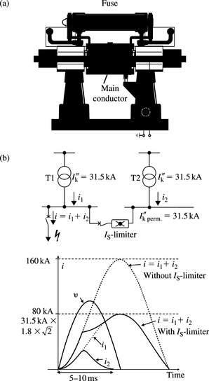
The first is the main conductor that carries the load current under normal unfaulted system operating conditions. The second is a parallel fuse with a high breaking capacity that limits the short-circuit current at the first current’s rise and interrupts it at the next current zero. Figure 9.6(b) shows the effect of IS-limiter operation where the two sources of fault currents are characterised by an rms current equal to 31.5 kA and a peak factor equal to 1.8 giving an initial peak asymmetric current of 80 kA. The IS-limiter is activated by a small charge that opens the main conductor and diverts the short-circuit current to the fuse. The normal instantaneous current through the IS-limiter is monitored by an electronic measuring and tripping circuit. Both the current and its rate of rise are continuously evaluated and compared to selected set points. If both set points are simultaneously reached, the IS-limiter trips and the total operating time to current interruption is 5–10 ms. After an operation, the IS-limiter insert (one unit per phase), i.e. the main conductor, the parallel fuse and the charge need to be replaced. These limiters can be used in a variety of applications such as to couple substation busbars, connection of two separate subsystems, connection in series with generator feeders or in parallel with a current limiting reactor, etc.
Since the current is generally limited and interrupted before the half cycle asymmetric peak is reached, as illustrated in Figure 9.6(b), the IS-limiter current will not contribute to this initial half cycle peak current. Therefore, the limiter can be modelled as a zero admittance (phase, PPS, NPS and ZPS) element in short-circuit analysis studies.
9.4.4 Permanently inserted current limiting series reactor
Short-circuit current limiting series reactors have been used in power systems at almost all voltage levels for decades. They introduce a leakage impedance into the current path which limits the fault current. Because they are permanently inserted in the system, i.e. under normal unfaulted system conditions, they have several disadvantages. These include: they introduce a voltage drop, have active and reactive power losses, may adversely affect the optimum distribution of power flow in interconnected networks and may also adversely affect the transient and dynamic stability performance of power systems. Series reactors are modelled using their leakage impedance as discussed in Chapter 4.
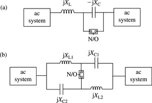
9.4.5 Series resonant current limiters using a bypass switch
To eliminate the active and reactive power losses in bus tie applications using single reactor component, an alternative is to use a power frequency tuned resonant series inductor and capacitor combination. The combination has a zero impedance under normal operating conditions. To limit the fault current, the capacitor element is shorted out using a fast closing bypass switch. A variant of this approach is to use a series/parallel arrangement of tuned inductors and capacitors in order to create two parallel tuned elements in series by the operation of a single bridging switch at the circuit mid-point. Both circuits are shown in Figure 9.7. Some of the disadvantages of these circuits are that a number of large components are mounted at line potential and there may be a risk of sub-synchronous resonance which may damage turbo-generator shafts. In the second circuit, if all the inductive and capacitive reactances are chosen to be equal, the impedance switches from zero to almost an infinite value, and while this is very attractive, may be impractical because of its significant adverse effect on downstream protection. Also, the shorting switch may have to close near zero voltage across the capacitor to avoid a very large transient current duty.
9.4.6 Limiters using magnetically coupled circuits
Figure 9.8 shows two configurations of magnetically coupled circuits. Two windings, a primary and a secondary, having equal number of turns are shown. The two windings are connected so that the same current flows through them and the primary winding MMF balances that of the secondary winding.
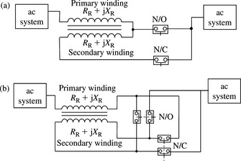
Figure 9.8 Fault current limiters using magnetically coupled circuits: flux cancelling limiter with (a) reverse secondary winding bypass and (b) secondary winding polarity changeover
During normal or unfaulted operation, the voltage induced across the self-inductance of the primary winding is cancelled by the voltage induced in the same primary winding due to the current flowing in the secondary winding, and vice versa. Therefore, the net voltage across each winding is zero. Since close mutual coupling between the two windings is required as well as safe clearances where high voltages are involved, an iron core would be required. The device would result in resistive losses. Because under normal unfaulted operation, the secondary MMF cancels out the primary MMF, this limiter is termed a flux cancelling limiter. A sensing and control circuit is required to detect the onset of short-circuit current and switch the device into the limiting mode.
Flux cancelling limiter with reverse secondary winding bypass
This is shown in Figure 9.8(a). When an external short-circuit fault occurs, the coupling between the two windings is broken by immediately closing the normally open switch and opening the normally closed switch. This effectively open circuits the secondary winding and causes the primary winding to appear as a series reactor with an impedance ZR that acts to limit the short-circuit current. The actions of the switches make the circuit appears as 1:1 transformer with an open-circuited secondary winding. The voltage rating of the normally closed switch is equal to the voltage across the primary winding under short-circuit conditions. This switch only carries the normal load current. The current rating of the normally open switch is equal to the limited short-circuit current and under unfaulted system conditions, the voltage across this switch is zero because it is equal to the voltage across the secondary winding.
Flux cancelling limiter with reverse parallel to series reconnection
This is shown in Figure 9.8(b). When an external short-circuit fault occurs, the direction of the secondary winding is reversed so that the induced voltage adds to the voltage across the self-inductance of each winding, instead of subtracting, and hence doubles the effective impedance in series with the network. The normally open switches carry the limited short-circuit current whereas the normally closed switches carry the load current.
9.4.7 Saturable reactor limiters
Saturable reactors have a non-linear voltage-current characteristic so that when the voltage across the reactor rises above a certain threshold, the reactor current increases disproportionately due to core saturation. As a result, its effective impedance reduces below that without saturation. Figure 9.9 illustrates a saturable reactor with a dc and an ac windings that are wound orthogonally on an iron core.
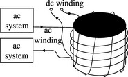
The amount of saturation is controlled by injecting a variable dc current into the dc control winding. With the exception for the core saturation, the current in the main ac winding is not affected by that in the dc control winding. Because the two windings are orthogonal, the mutual coupling between them is negligible. The device operates in the saturation region under normal unfaulted system conditions and must be quickly taken out of saturation upon the onset of short-circuit current. The increase in impedance offered by this limiter is generally small and may not be sufficient if appreciable current limitation is required. A conventional series iron core saturable reactor may also be used where saturation is obtained by injecting a dc current into the main winding.
9.4.8 Passive damped resonant limiter
Figure 9.10 illustrates one phase of a three-phase damped resonant limiter circuit using only passive components.
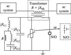
The limiter consists of an isolation transformer whose primary winding is connected in series with the system and a capacitor is connected across its secondary winding. A non-linear resistor, e.g. a varistor, or a fast closing triggered switch, is connected in parallel with the capacitor and a damped tuned filter is connected in parallel with the varistor. Under normal unfaulted system condition, the secondary circuit appears as a capacitor at 50 Hz that when transferred to the primary of the transformer, is equal to and hence cancels out the transformer’s leakage reactance. Therefore, at 50 Hz, the limiter appears as a short circuit except for the resistance of the transformer. When a short circuit fault occurs in the power system, the increase in current flowing in the transformer’s primary winding causes a corresponding increase in the secondary winding’s current. The rise in voltage across the secondary winding impedance would cause the varistor or switch to conduct and short circuit the capacitor. Thus, the effective impedance that remains in the primary circuit is the transformer’s leakage impedance and this acts to limit the fault current to the desired value. A circuit-breaker in parallel with the varistor or switch may be used to short circuit the secondary and reduce the energy absorption duty on the varistor.
The fault current limiting described can be obtained without the circuitry involving XL1, R, XL2 and XC2. However, with series capacitors in transmission systems, sub-synchronous resonance phenomenon has occurred and caused damage to turbo-generator shafts. Thus, the purpose of this circuitry is to provide damping at sub-synchronous frequencies. The circuit consists of a reactance XL1, and a ‘C’ filter whose XL2 and XC2 are tuned at power frequency (50 or 60 Hz), so that the damping resistor R is short-circuited at this frequency. XL1, is used because the filter can not be connected across the main capacitor XC1 to avoid short-circuiting this capacitor. The value of XL1 is chosen so that at power frequency, the parallel combination of XL1 and XC1 appears as a capacitive reactance whose value is equal to the leakage reactance of the series transformer.
In summary, the limiter has a negligible impedance under normal unfaulted system operation and a fault limiting reactance equal to the transformer’s leakage reactance under short-circuit conditions. A damping circuit is included to reduce the risk of sub-synchronous resonance. The modelling of this limiter as a leakage impedance in short-circuit studies is straightforward.
9.4.9 Solid state limiters using power electronic switches
Series resonant limiter using thyristor protected series capacitor
Figure 9.11(a) illustrates this type of limiter which is based on a flexible ac transmission system series compensation device called the thyristor protected series capacitor. In parallel with the capacitor is a power electronic switch that consists of anti-parallel thyristors. Under normal unfaulted system operation, the thyristor switches are not conducting current, and the series inductance and capacitance are tuned at power frequency. Therefore, only the inductor’s resistance remains in the circuit and this incurs active power losses. Under system fault conditions, the thyristor switches are made to conduct the fault current and bypass the capacitor thus inserting the reactor impedance into the fault path within a few milliseconds. The reactor acts to limit the fault current.

Series resonant limiter using thyristor controlled series capacitor
The circuit is illustrated in Figure 9.11(b) and is essentially a flexible ac transmission system series compensation device employing thyristor controlled series capacitor used for improving the power transfer capability of the network. Under normal system operating conditions, the thyristor conduction angles are small (firing angles are large), so that most of the current flows through the series capacitor. The effective impedance of the parallel inductor/capacitor combination is capacitive. However, when a short-circuit fault occurs, the firing angle of the thyristors is quickly reduced, so that the parallel inductor/capacitor combination changes to inductive thus limiting the fault current. Fault current limitation is generally an attractive by-product of these controlled series capacitor devices.
Solid state limiter using normally conducting power electronics switches
This type of fault limiter is illustrated in Figure 9.12.

It consists of a power electronics switch that is connected in series in the ac system. A fault limiting resistor or reactor is connected in parallel with the switch. Under normal unfaulted system operation, the switch conducts and carries the normal load current and the fault limiting resistor/reactor is short-circuited. When a system short-circuit fault occurs, the rising fault current is detected and the switch is turned off thus diverting the fault current to the parallel resistor/reactor which acts to limit the fault current. The fault current limiting is accomplished within a few milliseconds. The use of a current limiting resistor brings the useful benefit of reducing the phase angle difference between the voltage and current and quickly removing the dc fault current component. A varistor may be connected in parallel with the switch to limit the transient voltage that appears across it. The switches may accomplish the current switch off using gate turn off thyristors or modern alternatives. Because they are normally conducting, the switches incur on-state active power losses and these are typically 0.1–0.2% of the throughput power.
9.4.10 Superconducting fault current limiters
Background
A superconductor is a wire or a coil such as Bismuth-2233 or YBa2Cu3O7 that, when cooled, acts as a perfect conductor that has a zero resistance. Beyond a certain critical limit of a particular property, the conductor loses its superconductivity state and transition to a normal high resistive state. The property referred to is the conductor critical temperature, critical current or current density, or magnetic field. Figure 9.13 illustrates the magnetic field and resistance/current, properties of a superconductor. Cryogenic cooling equipment is used to cool the superconductor using liquid nitrogen and for high temperature superconductors, the cooling temperature is less than −100°C. The ‘high temperature’ term refers to material that becomes superconductors at temperatures that are typically above 30°K. To the author’s knowledge, 100°K has so far been achieved.
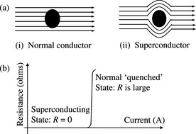
Figure 9.13 Basic electrical property of a superconductor: (a) magnetic flux lines and (b) resistance/current characteristics of a high temperature superconductor
The transition from the superconducting to the normal resistive state occurs automatically within a few milliseconds. No special devices or circuitry is needed to detect and trigger the fault limiting action since the transition in the state material is only dependent on the magnitude of the current flowing through it. In practical installations, recovery of the superconducting property should occur quickly in order to limit and withstand subsequent faults in the power system within a short period of time.
At the time of writing, superconducting fault current limiters remain mainly laboratory prototypes although the resistive type (see below) is nearing commercial use at low distribution voltages. Currently, there are four types of superconducting fault current limiters: (a) resistive superconducting limiter, (b) shielded inductance superconducting limiter, (c) saturated inductance superconducting limiter and (d) air-gap superconducting limiter. These are briefly described in the next section.
Resistive superconducting limiter
This limiter uses a superconductor connected in series in the system. Under normal unfaulted system operation, the limiter is in the superconducting state and has a zero resistance. When a system short-circuit fault occurs, the current or current density in the superconductor increases beyond a certain critical limit. The material loses its superconducting state and effectively becomes a high series resistance which limits the fault current. Figure 9.14 illustrates two connections: a series connection and a shunt connection.

Figure 9.14 (a) Resistive superconducting fault current limiter and (b) resistive superconducting fault current limiter with a parallel current limiting resistor/reactor
The main disadvantage of the series connection is that fast reclosing operation cannot be achieved in a cost-effective design because recovery of the limiter in readiness for a second limiting operation may take several minutes. This is caused by the heat generated in the conductor in the resistive state which must be dissipated to avoid conductor damage. In the shunt connection, a resistor or a reactor is connected in parallel with the limiter. Under normal unfaulted system operation, the current flows through the superconductor that has a zero resistance. Under faulted system conditions, the resistance of the limiter increases and the fault current is shared between the limiter and the resistor/reactor. If the design enables most of the fault current to flow through the resistor/reactor, multiple operation in a short period of time may be possible.
Shielded inductance superconducting limiter
In this type of limiter, a series transformer whose primary winding is connected in series in the power system is used. The secondary winding of the transformer is a single turn superconductor as illustrated in Figure 9.15(a).

Figure 9.15 Shielded inductance superconducting fault current limiter: (a) circuit schematic, (b) equivalent circuit and (c) equivalent circuit referred to primary side
During normal unfaulted system operation, the superconducting secondary winding is effectively short-circuited and its MMF balances that of the primary winding so that almost no flux penetrates the iron core. This introduces the transformer leakage reactance into the primary circuit as illustrated in Figure 15.9(a) and (b). During faulted system operation, the superconductor current increases beyond the critical value and becomes highly resistive. In order to achieve MMF balance, flux penetrates the iron core and the effective impedance appearing in the primary circuit is sharply increased thus limiting the fault current. The mass of iron and copper, cryogenics, civil engineering, overall size and cost can significantly exceed that of the resistive limiter so that practical applications may be unlikely unless new breakthroughs are made.
Saturated inductance superconducting limiter
In this type of limiter, illustrated in Figure 9.16, the line current flows through a series winding around an iron-cored reactor.

During normal unfaulted system operation, the iron of this reactor is held in saturation by a second dc superconducting winding and the effective reactance of the device is quite small. Under faulted system operation, the high fault current drives the core out of saturation and the effective reactance increases to the air core value. Two such devices are connected in series to provide limiting action for both polarities. The use of superconducting dc winding reduces steady state losses and because it remains in the superconducting state during system fault conditions, it enables instantaneous recovery. Another advantage is the improvement in the ratio of faulted to unfaulted impedance. The total mass of iron and copper required, as well as overall size, for a practical three-phase high voltage device are significant.
Air-gap superconducting limiter
This limiter is illustrated in Figure 9.17 and is similar to the shielded inductance limiter except that the secondary winding is replaced by a strip of superconductor inserted into an air gap in the iron core.

During normal unfaulted system operation, the superconductor expels the flux from the gap causing a high reluctance and a low primary inductance. However, during a faulted system condition, the superconductor can no longer support the currents necessary to expel the flux which now exceeds the superconductor critical limit and the magnetic reluctance drops causing the primary inductance to rise. The ratio of faulted to unfaulted limiter impedance may not be significant.
9.4.11 The ideal fault current limiter
The ideal fault current limiter should be invisible to the system in which it is installed except the short-circuit conditions it is designed to operate under. The ideal limiter should have the following characteristics:
(a) It should have a zero impedance and zero active and reactive power losses under normal unfaulted system conditions.
(b) It should detect, discriminate and respond to all types of short-circuit faults in less than 1 or 2 ms.
(c) When it responds, it should insert a very high limiting impedance to limit current flow. A mainly inductive impedance may be preferred in higher voltage networks although resistive limiters have the benefit of quickly suppressing the dc fault current component.
(d) It should automatically and quickly recover once the fault has been removed ready for another current limiting operation.
(e) It should be capable of performing successive current limiting operations without replacement.
(f) It should cause no unacceptable overvoltages or harmonics in the power system.
(g) It should have no adverse impact on power system protection performance.
In practical installations, such an ideal limiter is not achievable and various design compromises have to be made.
9.4.12 Applications of fault current limiters
There are many different possible applications of fault current limiters in low, medium, high and extra high voltage power networks as well as in industrial power systems. The most efficient, in terms of fault current reduction, and economic method is chosen depending on network and substation specific factors. A brief summary of the main applications is given below.
Figure 9.18 illustrates a case where the solid coupling of the 132 kV (110 kV) busbar is not possible due the short-circuit ratings of connected circuit-breakers being exceeded.
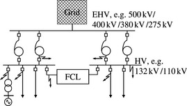
The busbar is split into two sections which are connected by a fault current limiter. The limiter’s impedance is chosen in order to reduce the short-circuit infeed from one side of the limiter for a fault on the other side, and vice versa, to well within switchgear ratings. For sufficiently large limiter impedance, the majority of the fault current on either side of the limiter is supplied through the transformers from the higher voltage network.
Figure 9.19 illustrates an extra high voltage substation with a significant amount of connected generation where the substation cannot be operated solid because the available short-circuit currents will exceed various switchgear and substation infrastructure ratings.

Busbar splitting through a fault current limiter is quite effective in limiting the short-circuit current magnitude to well within switchgear and substation infrastructure ratings.
Figure 9.20 illustrates a fault current limiter application in series with a transformer in a high-to-medium voltage substation. The limiter acts to limit transfomer fed short-circuit currents for faults on the medium voltage substation.
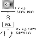
Figure 9.21 illustrates a fault current limiter application in series with a generator-transformer circuit. The limiter acts to limit the short-circuit current infeed from the generator for faults on the high voltage substation and the generator terminals.

Figure 9.22 illustrates a fault current limiter application in series with a generator-unit transformer that supplies the power station auxiliaries. The limiter acts to limit the short-circuit infeed from the generator and the grid via the unit transformer for faults on the unit board and lower voltages within the auxiliary system.
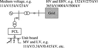
Figure 9.22 Fault current limiter in series with unit transformer supplying power station auxiliaries
Figure 9.23 illustrates a fault current limiter application in series with circuit feeders that export power from a large concentration of generation plant located at one or several locations.

Figure 9.23 Fault current limiter in series with exporting circuits connecting large concentration of generation
Figure 9.24 illustrates the connection of a generator through a fault current limiter to a medium voltage grid to limit the generator’s short-circuit contribution to faults within this grid. In this example, the limiter serves as an alternative to a transformer (and switchgear) connection to the high voltage grid.

Figure 9.25 illustrates fault current limiters in series with low impedance transformers and medium voltage substation busbars coupled via a resistive superconducting fault current limiter.
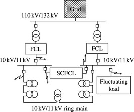
Operating the medium voltage busbars split reduces the short-circuit fault level at each busbar and reduces the supply voltage quality to customers supplied from the busbar section that supplies a fluctuating load such as an arc furnace load. Coupling the busbar sections through a superconducting fault current limiter, or ideally one that has a very low unfaulted impedance, increases the available short-circuit level at the busbar supplying the fluctuating load and improves the supply voltage quality.
9.4.13 Examples
Example 9.4
Using Example 9.1 system and data, calculate the short-circuit current for a single-phase short-circuit fault at the solid 132 kV busbar if each 400 kV/132 kV autotransformer is equipped with a neutral earthing reactor having a reactance of 10 Ω.
The value of the neutral earthing reactor in per cent on 100 MVA is equal to

The changes in the transformer ZPS T equivalent reactances and the new 400, 132 and 13 kV reactances are calculated as


The ZPS Thévenin’s equivalent impedance ‘seen’ at the 132 kV fault point is calculated using a simple star-to-delta transformation. Thus, XZThév. = 0.01877 pu. It is interesting to compare this with the value obtained in Example 9.3 of 0.00895 pu. The effect of the neutral earthing reactor is to double the ZPS Thévenin’s impedance at the 132 kV faulted busbar. It is also worth noting that the opening of the delta-connected tertiary windings is more effective in increasing the ZPS Thévenin’s impedance by a factor of 0.0324/0.01877= 1.72.
The single-phase fault current is equal to
Example 9.5
Figure 9.26(a) shows a power station having N operational but unloaded identical generators connected to a high voltage busbar through identical transformers. An interbus series reactor short-circuit limiter is used as shown in Figure 9.26(b). Derive a general expression relating the ratio of the three-phase short-circuit current with and without the reactor. Assume that the generators and transformers have equal MVA rating.
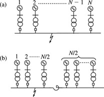
Let the PPS reactance of each generator and transformer be denoted XG and XT in pu on rating and let the series reactor’s PPS reactance on the generator’s rating be denoted XR. The three-phase short-circuit current for a fault on the high voltage busbar of Figure 9.26(a) is given by
Using a short-circuit limiting series reactor with N/2 generators arranged on either side, it can be easily shown that the three-phase short-circuit current for a fault on either side of the high voltage busbars is given by
Therefore, using the above two equations, we obtain

Clearly, the limiting value is found by setting N → ∞ giving a fault current of 50% of that without the reactor. However, it is more instructive to examine a practical situation where XG ≈ XT andXR ≈ XG. Thus,
and for N = 2, 4, 6, 8, and 10, IF(R)/IF = 0.83, 0.75, 0.7, 0.67 and 0.64, respectively. Small reductions in fault current occur as N increases and the current reduces asymptotically towards 0.5.
[1] Fernandez P.C., et al. Brazilian successful experience in the usage of current limiting rectors for short-circuit limitation. International Conference on Power System Transients (IPST 05). Montreal, Canada. Paper No. IPST05-215. 19–23 June 2005.
[2] Parton K.C. A new power system fault limiter. Electrical Review International. February 1978;Vol. 202(No. 5):63-65.
[3] Salim K.M., et al. Preliminary experiments on saturated DC reactor type fault current limiter. Preparation of MT-17, Geneva, Switzerland. 24–28 September 2001.
[4] Ihara, S., et al., Design options for passive fault current limiter, 1 River Road-Schenectady, NY 12345, USA.
[5] Tleis N., et al. Design of a 400 kV passive fault current limiter. International Conference on Switchgear and Substations. Tokyo, Japan. 2000.
[6] Putrus, G.A., et al., A Static Fault Current Limiter and Circuit Breaker Employing GTO Thyristor School of Engineering, University of Northmbria, Newcastle.
[7] Weller, R.A., et al., Computer Modelling of Superconductivity, Cambridge, UKCB3 0HE.
[8] session, ParisRaju B.P., et al. Fault current limiting reactor with supercon ducting DC bias winding. International Conference on Large High Voltage Electric Systems. 1–9 September 1982.
[9] Power A.J. An overview of transmission fault current limiters. IEE Colloquium on Fault Current Limitus-A Look at Tomorrow, Digest. 1995/026, IEE, London. 1995.
[10] IEE Colloquium on Fault Current Limiters, a Look at Tomorrow, Digest. 1995/026. IEE, London. 1995.
[11] Gubser D.U. Superconductivity: an emerging power-dense energy-efficient technology. IEEE Transactions on Applied Superconductivity. December 2004;Vol. 14(No. 4):71-75.