14
UTILITY APPLICATIONS OF POWER ELECTRONICS
14.1 INTRODUCTION
In previous chapters, various power electronic systems were described to use electricity efficiently and harness energy from renewable sources. In this chapter, all these applications, and new ones, are compiled in the context of utility applications. Such power electronics applications in utility systems are growing very rapidly, which promise to change the landscape of future power systems in terms of generation, operation, and control. The goal of this chapter is to briefly present an overview of these applications to prepare students for new challenges in the deregulated utility environment and to motivate them to take further courses in this field, for instance, the advanced-level graduate course designed at the University of Minnesota to discuss these topics in detail [1, 2].
In discussing these applications, we will observe that the power electronic converters are the same or modifications of those that we have already discussed in earlier chapters. Therefore, within the scope of this book, it will suffice to discuss these applications in terms of the block diagrams of various converters. These utility applications of power electronics can be categorized as follows:
Distributed Generation (DG)
–Renewable resources (wind, photovoltaic, etc.)
–Fuel cells and micro-turbines
–Storage-batteries, super-conducting magnetic storage, flywheels
- Power Electronic Loads—Adjustable Speed Drives
- Power Quality Solutions
– Dual feeders
– Uninterruptible power supplies
– Dynamic voltage restorers
- Transmission and Distribution (T&D): HVDC and FACTS [3]
–High voltage DC (HVDC) and HVDC-light
–Flexible AC transmission (FACTS)
- Shunt compensation
- Series compensation
- Static phase angle control and unified power flow controllers
14.2 POWER SEMICONDUCTOR DEVICES AND THEIR CAPABILITIES
Figure 14.1a shows the commonly used symbols of power devices. The power handling capabilities and switching speeds of these devices are indicated in Figure 14.1b. All these devices allow current flow only in their forward direction (the intrinsic anti-parallel diode of MOSFETs can be explained separately). Transistors (intrinsically or by design) can block only the forward polarity voltage, whereas thyristors can block both forward and reverse polarity voltages. Diodes are uncontrolled devices that conduct current in the forward direction and block a reverse voltage. At very high power levels, integrated-gate controlled thyristors (IGCTs), which have evolved from the gate-turn-off thyristors, are used. Thyristors are semi-controlled devices that can switch-on at the desired instant in their forward-blocking state but cannot be switched off from their gate and hence rely on the circuit in which they are connected to switch them off. However, thyristors are available in very large voltage and current ratings.

FIGURE 14.1 Power semiconductor devices.
These devices are available in a large range of voltage and current ratings for use in a variety of applications. Moreover, they can be connected in series and in parallel to extend this range further. As an example, IGBTs, which are commonly used in a very large range of utility-related applications, are available as a single module from a manufacturer with a rating of 600 A/6,500 V.
14.3 CATEGORIZING POWER ELECTRONIC SYSTEMS
In a very broad sense, the role of power electronics in these power system applications can be categorized as follows:
14.3.1 Solid-State Switches
By connecting two thyristors in anti-parallel (back-to-back), as shown in Figure 14.2, it is possible to realize a solid-state switch that can conduct current in both directions and turn on or turn off in an AC circuit with a delay of no more than one-half the line-frequency cycle. Such switches are needed for applications such as dual feeders, shunt-compensation for injecting reactive power at a bus for voltage control, and series-compensation of transmission lines.

FIGURE 14.2 Back-to-back thyristors to act as a solid-state switch.
14.3.2 Converters as an Interface
Power electronic converters provide the needed interface between the electrical source, often the utility, and the load, as shown in Figure 14.3. The electrical source and the electrical load can, and often do, differ in frequency, voltage amplitudes, and the number of phases. The power electronics interface allows the transfer of power from the source to the load in the most energy-efficient manner, in which it is possible for the source and load to reverse roles. These interfaces can be classified as below.

FIGURE 14.3 Power electronics interface.
14.3.2.1 Voltage-Link Systems
The semiconductor devices such as transistors of various types and diodes can only block forward-polarity voltages. These devices with only unipolar voltage-blocking capability have led to the structure with two converters, where the DC ports of these two converters are connected to each other with a parallel capacitor forming a DC link, as shown in Figure 14.4, across which the voltage polarity does not reverse, thus allowing unipolar voltage-handling transistors to be used within these converters. The transfer of power can be reversed in direction by reversing the direction of currents associated with the DC-link system.

FIGURE 14.4 Block diagram of the voltage-link systems.
Voltage-link converters consist of switching power-poles as the building blocks, which can synthesize the desired output by means of pulse-width modulation (PWM) and have bidirectional power flow capability. Such switching power-poles can be modeled by means of an ideal transformer with a controllable turns ratio, as discussed in Chapter 12.
14.3.2.2 Current-Link Systems
Thyristors can block voltages of both polarities but conduct current only in the forward direction. This capability has led to the interface realized by thyristor-converters with a DC-current link in the middle, as shown in Figure 14.5. The transfer of power can be reversed in direction by reversing the voltage polarity of the DC link, but the currents in the link remain in the same direction. This structure is used at very high power levels, at tens of hundreds of megawatts, for example, in high-voltage DC (HVDC) transmission.

FIGURE 14.5 Block diagram of the current-link systems.
In the following sections, various utility applications and the role of power electronics in them are examined further.
14.4 DISTRIBUTED GENERATION (DG) APPLICATIONS
Distributed generation promises to change the landscape of how power systems of the future will be operated and controlled. These generators may have decentralized (local) control, in addition to a central supervisory control. There is a move away from large central power plants toward distributed generation due to environmental and economic reasons. Renewable resources such as wind and photovoltaic systems are growing in their popularity. There are proposals to place highly efficient small-scale power plants, based on fuel cells and micro-turbines, near load centers to simultaneously avoid transmission congestion and line losses. Many distributed generation systems are discussed below.
14.4.1 Wind-Electric Systems
Wind energy is an indirect manifestation of solar energy caused by uneven heating of the earth’s surface by the sun. Out of all renewable energies, wind has come a long way, and still, this potential is just beginning to be realized. Figure 14.6 shows the wind potential by states in the United States, where there are several areas with good to excellent wind conditions.

FIGURE 14.6 Wind-resource map of the United States. This information has been reprinted from the National Renewable Energy Laboratory’s Dynamic Maps, GIS Data, & Analysis Tools webpage (http://www.nrel.gov/gis/wind.html), map “US Wind Resource Map.” Accessed August 4, 2011.
Commonly used schemes for power generation in windmills require a gearing mechanism because the wind turbine rotates at very slow speeds, whereas the generator operates at high speed close to the synchronous speed, which at the 60-Hz line frequency would be 1800 rpm for a 4-pole and 900 rpm for an 8-pole machine. Therefore, the nacelle contains a gearing mechanism that boosts the turbine speed to drive the generator at a higher speed; the need for a gearing mechanism is one of the inherent drawbacks of such schemes. There are proposals to use direct-drive (without gears) permanent magnet machines in very large sizes; however, in practice, most windmills use gearing. This sub-section describes various types of wind-generation schemes.
14.4.1.1 Induction Generators, Directly Connected to the Grid
As shown in Figure 14.7a, this is the simplest scheme, where a wind-turbine-driven squirrel-cage induction generator is directly connected to the grid through a back-to-back connected thyristor-pair for soft start. Therefore, it is the least expensive and uses a rugged squirrel-cage rotor induction machine.
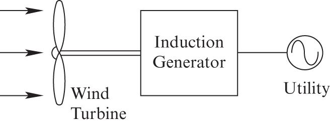
FIGURE 14.7A Induction generator directly connected to the grid.
For the induction machine to operate in its generator mode, the rotor speed must be greater than the synchronous speed. The drawback of this scheme is that since the induction machine always operates very close to the synchronous speed, this scheme is not optimum at low and high wind speeds compared to the variable speed schemes described below. Another disadvantage of this scheme is that a squirrel-cage induction machine always operates at a lagging power factor (that is, it draws reactive power from the grid as an inductive load would). Therefore, a separate source, for example, shunt-connected capacitors, is often needed to supply the reactive power to overcome the lagging power factor operation of the induction machine.
14.4.1.2 Doubly-Fed, Wound-Rotor Induction Generators
The scheme in Figure 14.7b utilizes a wound-rotor induction machine where the stator is directly connected to the utility supply, and the rotor is injected with desired currents through a power-electronics interface. Typically, four-fifths of the power flows directly from the stator to the grid, and only one-fifth of the power flows through the power electronics in the rotor circuit. The drawback of this scheme is that it uses a wound-rotor induction machine where the currents to the three-phase wound rotor are supplied through slip-rings and brushes, which require maintenance. In spite of the fact that power electronics is expensive, and since it is rated only one-fifth of the system rating, the overall cost is not much higher than the previous scheme. However, there are several distinct advantages over the previous scheme, as described below.

FIGURE 14.7B Doubly-fed, wound-rotor induction generator.
The scheme using a doubly fed wound-rotor induction machine can typically operate in a range of ![]() around the synchronous speed, and hence it is able to capture more power at lower and higher wind speeds compared to the previous scheme because it can operate at above, as well as below, the synchronous speed. It can also supply reactive power, whereas, in the previous scheme, the squirrel-cage induction machine only absorbs reactive power. Therefore, the scheme using a doubly fed wound-rotor induction machine is quite popular in windmills being installed in the United States.
around the synchronous speed, and hence it is able to capture more power at lower and higher wind speeds compared to the previous scheme because it can operate at above, as well as below, the synchronous speed. It can also supply reactive power, whereas, in the previous scheme, the squirrel-cage induction machine only absorbs reactive power. Therefore, the scheme using a doubly fed wound-rotor induction machine is quite popular in windmills being installed in the United States.
14.4.1.3 Power Electronics Connected Generator
In the third scheme shown in Figure 14.7c, a squirrel-cage induction generator or a permanent-magnet generator is connected to the grid through a power electronics interface. This interface consists of two converters. The converter at the generator-end supplies the reactive power excitation needed if it is an induction generator. Its frequency of operation is controlled to be optimal for the prevailing wind speed. The converter at the line-end is capable of absorbing or supplying reactive power in a continuous manner. This is the most flexible arrangement using a rugged squirrel-cage machine or a high-efficiency permanent-magnet generator, which can operate in a very wide wind-speed range and is the likely contender for the future arrangements as the cost of the power electronics interface, which must handle the entire power output of the system, is continuing to go down.

FIGURE 14.7C Power electronics connected generator.
14.4.2 Photovoltaic (PV) Systems
Photovoltaic systems are the ultimate in distributed generation and have even greater potential than wind-electric systems. In PV systems, the PV arrays (typically four of them connected in series) provide a voltage of 52 to 90 V DC, which the power electronic system, such as that shown in Figure 14.8, converts to 120 V/60 Hz sinusoidal voltage suitable for interfacing with the single-phase utility. Such PV modules can be connected in parallel for higher output capacity. Larger arrays are interfaced with a three-phase utility grid.

FIGURE 14.8 Photovoltaic systems.
Figure 14.9 shows a 127 kW rooftop PV system, one of the largest roof-integrated federal systems in the United States.

FIGURE 14.9 A rooftop PV system. Source: www.NREL.gov
14.4.3 Fuel Cell Systems
Lately, there has been a great deal of interest in and effort being devoted to fuel cell systems. The reason has to do with their efficiency, which can be as high as 60%. The input to the fuel cell can be hydrogen, natural gas, or gasoline, and the output is a DC voltage, as shown in Figure 14.10 [4]. The need for power electronics converters to interface with the utility is the same in the fuel-cell systems as that for the photovoltaic systems.

FIGURE 14.10 Fuel cell V-I relationship and cell power. Source: U.S Department of Energy / Public Domain.
14.4.4 Micro-Turbines
These use highly efficient aircraft engines, for example, to produce peak power when it is needed, with natural gas as the input fuel. To improve efficiency, the turbine speed should be allowed to vary based on loading. This will cause the frequency of the generated output to vary, requiring a power-electronic interface like that in adjustable-speed drives.
14.4.5 Energy Storage Systems
Although not a primary source of energy, storage plants offer the benefit of load-leveling and peak-shaving in power systems because of the diurnal nature of electricity usage. Energy is stored, usually at night when the load demand is low, and supplied back during the peak-load periods.
It is possible to store energy in lead-acid batteries (other exotic high-temperature batteries are being developed), in superconducting magnetic energy storage (SMES) coils, and in the inertia of flywheels. All these systems need a power electronic interface, where the interface for the flywheel storage is shown in Figure 14.11.

FIGURE 14.11 Flywheel storage system.
14.5 POWER ELECTRONIC LOADS
As discussed in Chapter 1, power electronics is playing a significant role in energy conservation, for example, as users discover the benefits of reduced energy consumption and better process control by operating electric drives at adjustable speeds. An adjustable-speed drive (ASD) is shown in Figure 14.12 in a block diagram form.

FIGURE 14.12 Adjustable-speed drive.
Power electronic loads of this type often use an interface with the utility that results in distorted line currents. These currents result in distorted voltage waveforms, affecting the neighboring loads. However, it is possible to design the utility interface (often called the power-factor-corrected front-end) that allows sinusoidal currents to be drawn from the grid. With the proliferation of power electronic loads, standards are being enforced that limit the amount of distortion in currents drawn.
14.6 POWER QUALITY SOLUTIONS
Poor quality of power can imply any of the following: distorted voltage waveforms, unbalances, swells and sags in voltage and power outages, and so on. This problem is exacerbated in a deregulated environment where utilities are forced to operate at marginal profits, resulting in inadequate maintenance of equipment. In this section, we will also see that power electronics can solve many of the power quality problems.
14.6.1 Dual Feeders
The continuity of service can be enhanced by dual power feeders to the load, where one acts as a backup to the other that is supplying the load, as shown in Figure 14.13.

FIGURE 14.13 Dual-feeders.
Using back-to-back connected thyristors, acting as a solid-state switch, it is possible to switch the load quickly, without interruption, from the main feeder to the backup feeder and back.
14.6.2 Uninterruptible Power Supplies
Power outages, even for a few cycles, can be very disruptive to critical loads. To provide immunity from such outages, power-electronics-based uninterruptible power supplies (UPS), shown in Figure 14.14, can be used, where the energy storage can be by means of batteries, SMES (superconducting magnetic energy storage), flywheels, or ultra-capacitors.

FIGURE 14.14 Uninterruptible power supplies.
14.6.3 Dynamic Voltage Restorers
Dynamic voltage restorers (DVR), shown in Figure 14.15, can compensate for voltage sags or swells by injecting a voltage ![]() in series with that supplied by the utility.
in series with that supplied by the utility.

FIGURE 14.15 Dynamic voltage restorers.
14.7 Transmission and Distribution (T&D) Applications
In the past, utilities operated as monopolies, where users had little or no option in selecting whom they could purchase power from. The recent trend, which seems irreversible in spite of recent setbacks, is to deregulate where utilities must compete to sell power on an open market, and the customers have a choice of selecting their power provider. In such an environment, utilities that were vertically integrated are now forced to split into generation companies that produce power and transmission-line operators that maintain the transmission and distribution network for a fee.
In this deregulated environment, it is highly desirable to have the capability to dictate the flow of power on designated power lines, avoiding overloading of transmission lines and excessive power losses in them. In this section, we will look at some such options.
14.7.1 High-Voltage DC (HVDC) Transmission
Direct current (DC) transmission represents the ultimate flexibility, isolating two interconnected AC systems from the requirement of operating in synchronism or even at the same frequency. High-voltage DC (HVDC) transmission systems using thyristor-based current-link converters have now been in operation for several decades. Lately, systems at somewhat lower voltages using IGBT-based voltage-link converters have been installed. Both of these types of systems are discussed below.
14.7.1.1 Thyristor-Based Current-Link HVDC Transmission Systems
Figure 14.16 shows the block diagram of an HVDC transmission system, where power is transmitted over DC lines at high voltages in excess of 500 kV. First, the voltages in AC system 1 at the sending end are stepped up by means of a transformer. These voltages are rectified into DC by means of a thyristor-based converter, where the AC line voltages provide the commutation of current within the converter, such that AC currents drawn from system 1 turn into DC current on the other side of the converter. These currents are transmitted over the DC line, where additional series inductance is added to ensure that the DC current is smooth and free of ripple as much as possible. At the receiving end, there are thyristor-based converters, which convert the DC current into AC currents and inject them into the AC system 2, through a step-down transformer. The roles of the sending and the receiving ends can be reversed by reversing the voltage polarity in the DC system.

FIGURE 14.16 HVDC voltage-link system block diagram (transformers are not shown).
For example, a current-link HVDC transmission system in the western part of the United States transmits 3,100 MW at ![]() over a distance of 1,361 km. At very high power levels in excess of 1,000 MW, the use of thyristors, at least for now, represents the only reasonable choice.
over a distance of 1,361 km. At very high power levels in excess of 1,000 MW, the use of thyristors, at least for now, represents the only reasonable choice.
14.7.1.2 HVDC Transmission System Using Voltage-Link IGBT-Based Converters
At lower power levels compared to those carried by thyristor-based HVDC transmission lines, the alternative is to use a voltage-link system, whose block diagram is shown in Figure 14.17. In such a system, the direction of power flow is reversed by changing the direction of current in the DC line. As an example, a voltage-link system in the eastern part of the United States operates at ![]() and is rated at 330 MW.
and is rated at 330 MW.

FIGURE 14.17 Block diagram HVDC transmission using a voltage-link system.
14.7.2 Flexible AC Transmission Systems (FACTS) [3]
DC transmission systems discussed earlier are an excellent choice where a large amount of power needs to be transmitted over long distances or if the system stability is a serious issue. In existing AC transmission networks, limitations on constructing new power lines and their cost have led to other ways to increase power transmission capability without sacrificing the stability margin. These techniques may also help in directing the power flow to designated lines.
Power flow on a transmission line connecting two AC systems in Figure 14.18 is given as

FIGURE 14.18 Power flow on a transmission line.
where ![]() and
and ![]() are the magnitudes of voltages at the two ends of the transmission line,
are the magnitudes of voltages at the two ends of the transmission line, ![]() is the line reactance, and
is the line reactance, and ![]() is the angle between the two bus voltages.
is the angle between the two bus voltages.
Equation (14.1) shows that the power flow on a transmission line depends on three quantities: (1) the voltage magnitude ![]() , (2) the line reactance
, (2) the line reactance ![]() , and (3) the power angle
, and (3) the power angle ![]() . Various devices that are based on rapidly controlling one or more of the above three quantities are discussed in the following sections:
. Various devices that are based on rapidly controlling one or more of the above three quantities are discussed in the following sections:
14.7.2.1 Shunt-Connected Devices to Control the Bus Voltage Magnitude E
The reactive power compensation is very important and may even be necessary at high loadings to avoid voltage collapse. Shunt-connected devices, as shown in Figure 14.19, can draw or supply reactive power from a bus, thus controlling the bus voltage, albeit in a limited range, based on the internal system reactance.

FIGURE 14.19 Shunt-connected devices for voltage control.
Various forms of such devices are being used in different combinations. These include thyristor-controlled reactors (TCR), shown in Figure 14.19a, and thyristor-switched capacitors (TSC), shown in Figure 14.19b, for static var compensation (SVC). The advanced static var compensator (STATCOM) shown in Figure 14.19c can draw or supply reactive power.
Shunt-compensation devices have the following limitations for controlling the flow of active power:
- A large amount of reactive power compensation, depending on the system’s internal reactance, may be required to change the voltage magnitude. Of course, the voltage can only be changed in a limited range (utilities try to maintain bus voltages at their nominal values), which has a limited effect on the power transfer given by Equation (14.1).
- Most transmission systems consist of parallel paths or loops. Therefore, changing the voltage magnitude at a given bus changes the loading of all the lines connected to that bus, and there is no way to dictate the desired change of power flow on a given line.
14.7.2.2 Series-Connected Devices to Control the Effective Series Reactance X
These devices, connected in series with a transmission line, partially neutralize (or add to) the transmission line reactance. Therefore, they change the effective value of ![]() in Equation (14.1), thus allowing the active power flow
in Equation (14.1), thus allowing the active power flow ![]() to be controlled. Various forms of such devices have been used. These include the thyristor-controlled series capacitor (TCSC), also known as thyristor-controlled series compensator, shown in Figure 14.20. It should be noted that just as STATCOM with higher performance capabilities is a solid-state equivalent of an SVC, similarly, there is a solid-state equivalent of TCSC called SSSC (static synchronous series compensator), which injects a controlled voltage in series with the transmission line that either lags or leads the line current.
to be controlled. Various forms of such devices have been used. These include the thyristor-controlled series capacitor (TCSC), also known as thyristor-controlled series compensator, shown in Figure 14.20. It should be noted that just as STATCOM with higher performance capabilities is a solid-state equivalent of an SVC, similarly, there is a solid-state equivalent of TCSC called SSSC (static synchronous series compensator), which injects a controlled voltage in series with the transmission line that either lags or leads the line current.

FIGURE 14.20 Thyristor-controlled series compensator (TCSC).
14.7.2.3 Static Phase Angle Control and Unified Power Flow Controller (UPFC)
Based on Equation (14.1), a device connected to a bus in a substation, as shown in Figure 14.21a, can influence power flow in three ways:

FIGURE 14.21 Unified power flow controller (UPFC).
- Controlling the voltage magnitude E,
- Changing the line reactance X, and/or
- Changing the power angle δ.
Such a device, called the unified power flow controller (UPFC), can affect power flow in any combination of the ways listed above. The block diagram of a UPFC is shown in Figure 14.21a at one side of the transmission line. It consists of two voltage-source switch-mode converters. The first converter injects a voltage ![]() in series with the phase voltage such that
in series with the phase voltage such that
Therefore, by controlling the magnitude and the phase of the injected voltage ![]() within the circle shown in Figure 14.21b, the magnitude and the phase of the bus voltage
within the circle shown in Figure 14.21b, the magnitude and the phase of the bus voltage ![]() can be controlled. If a component of the injected voltage
can be controlled. If a component of the injected voltage ![]() is made to be 90 degrees out of phase, for example leading with respect to the current phasor
is made to be 90 degrees out of phase, for example leading with respect to the current phasor ![]() , then the transmission line reactance
, then the transmission line reactance ![]() is partially compensated.
is partially compensated.
The second converter in a UPFC is needed for the following reason: since converter 1 injects a series voltage ![]() , it delivers real power
, it delivers real power ![]() , and the reactive power
, and the reactive power ![]() to the transmission line (where
to the transmission line (where ![]() and
and ![]() can be either positive or negative):
can be either positive or negative):
Since there is no steady-state energy storage capability within a UPFC, the power ![]() into converter 2 must equal
into converter 2 must equal ![]() if the losses are ignored:
if the losses are ignored:
However, the reactive power ![]() bears no relation to
bears no relation to ![]() and can be independently controlled within the voltage and current ratings of converter 2:
and can be independently controlled within the voltage and current ratings of converter 2:
By controlling ![]() to control the magnitude of the bus voltage
to control the magnitude of the bus voltage ![]() , UPFC provides the same functionality as that of an advanced static var compensator STATCOM. A UPFC combines several other functions: static var compensator, phase-shifting transformer, and controlled series compensation.
, UPFC provides the same functionality as that of an advanced static var compensator STATCOM. A UPFC combines several other functions: static var compensator, phase-shifting transformer, and controlled series compensation.
REFERENCES
- 1. N. Mohan, A. Jain, P. Jose, and R. Ayyanar, “Teaching Utility Applications of Power Electronics in a First Course on Power Systems,” IEEE Transactions on Power Systems 19 (February 2004): 40–47.
- 2. N. Mohan, First Course on Power Systems (New York: John Wiley & Sons, 2011).
- 3. N.G. Hingorani, and L. Gyugyi, Understanding FACTS (New York,: IEEE Press, 2000).
- 4. D. Collins, “DOE FE Distributed Generation (DG) Fuel Cells Program,” IEEE Applied Power Electronics Conference, March 6–10, 2005, Austin, TX.
PROBLEMS
- 14.1 Show the details and the average representation of converters in Figures 14.7b and 14.7c for wind-electric systems.
- 14.2 Show the details and the average representation of converters in Figure 14.8 for a photovoltaic system.
- 14.3 Show the details and the average representation of converters in Figure 14.11 for a flywheel storage system.
- 14.4 Show the details and the average representation of converters in Figure 14.12 for an adjustable-speed drive.
- 14.5 Show the details and the average representation of converters in Figure 14.14 for a UPS.
- 14.6 Show the details and the average representation of converters in Figure 14.15 for a DVR.
- 14.7 Show the details and the average representation of converters in Figure 14.16 for a current-link HVDC transmission system.
- 14.8 Show the details and the average representation of converters in Figure 14.17 for a voltage-link HVDC transmission system.
- 14.9 Show the details and the average representation of the converter in Figure 14.19c for a STATCOM.
- 14.10 Show the details and the average representation of converters in Figure 14.21a for a UPFC system.