If you have played any 3D games or worked on any programs that involve graphics, you may have heard of OpenGL. You may have read the term on a game box or on a web site, or had some other programmer suggest to you that you might want to check out OpenGL. What is this OpenGL thing and how do you use it for your own purposes?
Whether you are totally new to OpenGL programming or you already know a bit about it, this and the next two chapters will bring you up to speed with developing in OpenGL ES for the iPhone.
There are a few main ways that you can draw graphics onto the iPhone screen:
You can make a custom UI view and put some Quartz 2D drawing code in the
drawRect:method.You can use Core Animation layers and provide their graphics content via their delegate methods.
You can render your graphics with OpenGL ES.
If you have been doing graphics on the iPhone without OpenGL, then you have either been drawing directly with Quartz 2D or providing images to views or layers and using Core Animation. OpenGL is a very different beast. With OpenGL ES, you are setting up a scene, which the OpenGL engine will draw for you. This is known as rendering. Whereas using the UIKit and Quartz 2D is like drawing a sketch on a pad of paper, using OpenGL is more like putting a bunch of objects on a table and taking a picture.
OK, but what is OpenGL?
OpenGL stands for Open Graphics Language, and as the name implies, it is open and free for anyone to use. Due to OpenGL's openness, it is used on many platforms. OpenGL ES is the embedded system version, which is a smaller subset of the OpenGL API that you might use if you wanted to do graphics on the desktop. From here on out, I am going to use the term OpenGL to collectively refer to both the OpenGL ES implementation that is on the iPhone and more generic OpenGL concepts.
Why would you want to use OpenGL?
If you need some extra speed, or want to move into the exciting world of 3D, then you may want to have a look at building your game with OpenGL. Moving to OpenGL is not terribly hard, but it will definitely add some extra complexity to your game application, so it is good to know when to use OpenGL and when you can get away without it.
If you are planning on a 3D game, you are most likely going to want to use OpenGL. However, many 2D games can also benefit from the added performance that you get from OpenGL. If your game is fast-paced and requires that extra bit of performance, or if your game has a lot of moving images on the screen at one time, you might want to consider moving your code over to OpenGL.
In this chapter, I am going to focus on the basics of OpenGL on iPhone, covering what it takes to build a 2D game in OpenGL. The techniques used to build a high-performance 2D game are very similar to those for building a 3D game, and in later chapters, I will talk about making the jump to 3D.
If you've been using the UIKit and Quartz 2D, you know that they are designed to make it very easy to draw stuff—all the complicated underlying hardware concerns are abstracted away from your code, and you never need to worry about them. OpenGL is a lower-level API. In order for OpenGL to be able to perform well, the programmer needs to do some harder work to get the data into a format that OpenGL can use. This means you will need to do some things in a way that is better for the hardware and more complicated for your program. This may sound daunting, but the trade-off is greatly enhanced performance and more control over your graphics output.
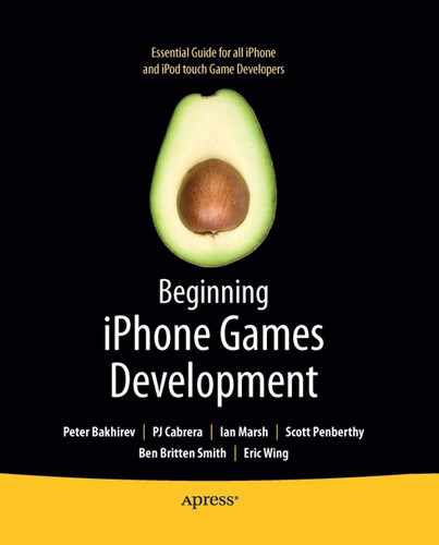
Having OpenGL render a scene is very much like taking a picture. So, before we get into any technical jargon, let's step back and take a look at what you need to do take a photograph of something.
Let's pretend we want to take a picture of some solid shapes on a table. How do we do that?
First, we need a table and some shapes. Great! That's easy. The table and the shapes are the subjects of the photograph. They are the stuff we want to see in the final photo. Let's call whatever it is we want to see in the final photo the scene that we want to capture.
OK, we have our scene set with our shapes on the table. Now we need a camera. Our camera will have two main parts: a lens and a recorder. The recorder can be a bit of film, a digital CCD, or magical pixies that paint whatever they see very quickly. The important thing is that the recorder makes an image of whatever it can see through the lens, and that image is our rendering.
We have almost everything we need to take a photo, but there is one more requirement: a perspective. We need to decide where we want to put the camera to take the photo. Do we want to look straight down on the objects? Maybe view them from the side? This is our camera position.
Once we have these four parts: a scene, a lens to look through, something that will record what it sees, and a position to put the camera, we can finally take our photo (check out Figure 6-1).
Now we can start to think about how OpenGL works. As I mentioned earlier, you don't draw your scenes— you build them and OpenGL renders them. Unfortunately, OpenGL does not have a table to put things on, so you need to build that. You also need to build the objects that go on that table. This can sound a bit difficult, but once you get used to it, you might find you prefer this build-and-render method over explicit drawing.
In order to be able to tell OpenGL where our objects are and what they look like, we need to figure out how to specify things in 3D space. To do this, we use a matrix.
A matrix is actually a fairly complex mathematical concept, and you could spend a whole semester at a university learning about matrixes and still not understand them fully (as I did). Luckily for us, OpenGL will handle all of the hard math, so we just need to understand the basics.
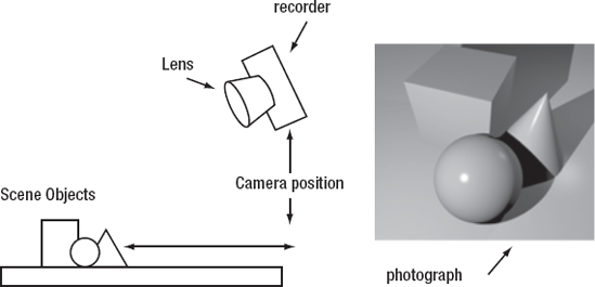
A matrix is composed of three components: a position (also known as the translation), a rotation, and a scale. These things are probably exactly what you think they are. The translation is where in space the object is placed. The rotation defines how the object is oriented. The scale is how big the object is. Take a look at Figure 6-2 to see these three components in action.
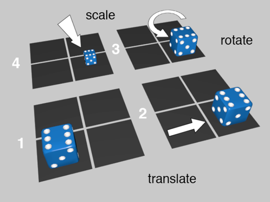
Figure 6.2. If we start at image 1 and we change the translation of our die, we get image 2. We then rotate the die and get image 3. Finally, we scale down the die and get image 4.
Note
I want to give a quick shout-out to Neil from Tin Man Games for allowing me to use one of their lovely dice models from their iPhone Gamebook Adventures applications (http://GamebookAdventures.com).
In Figure 6-2, our die gets translated to the right by one square, then rotated counterclockwise by 90 degrees, then scaled down to half its original dimensions (which is an eighth of its original size). If we put all three of those operations together in one blob, that blob is the matrix for that object.
How do we specify these three things? We need to define a frame of reference. This sounds complicated, but it's really easy. If you have done some 2D graphics, you already know about the x and y axes. The x axis is basically left and right across the screen, and the y axis is up and down. We just need one more axis, which we will call z, and that will be into the screen and out of the screen (see Figure 6-3).
So, if we want to specify the position of some object, we now have a frame of reference. We can say that an object is x units from the left, y units up, and z units back. Easy!
Scaling is similarly simple. We define the scale multiplier for each axis. So, if we wanted to make our object half its length in the x direction, we would scale it by 0.5 times x, 1 times y, and 1 times z. We multiply y and z by 1 so that they don't change (see Figure 6-4).

Rotations are only slightly more complicated. We need to define a rotation angle and then an axis to rotate around. It is easiest if you imagine that we are always rotating around one of the axes we defined earlier—the x, y, or z axis.
What does it mean to rotate around the y axis? Imagine that we have the y axis from Figure 6-3. We take that and spear it through our object, right in the center. This will be the pivot of the rotation. Using that pivot, we spin our object however many degrees we want (see Figure 6-5).
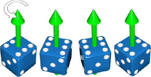
Figure 6.5. Rotation around the y axis. From left to right, we see the die rotate counterclockwise 90 degrees in three steps.
Now, if we combine a couple of different rotations, we can define any arbitrary orientation we want. Just imagine that we rotate first around the y axis and then around the x axis, as in Figure 6-6. We could then go on and do some rotation around the z axis as well. These three axes allow us to build any arbitrary orientation for our object.

Figure 6.6. Compound rotations. Technically speaking, we can actually get from the leftmost orientation to the rightmost with a single rotation around a vector, but it is much simpler to think in terms of compound rotations.
So, we have these three bits: the translation, the rotation, and the scale. Put them together, and we get a matrix. Matrixes are actually super helpful, as they can be multiplied together. How does this work? Let's look at a real-world example.
If you have some dice sitting on a table, and you move the table, the dice will go with it. If you take the house that the table is in and move it, the table goes with the house, and the dice go with the table. (If we pretend for a moment that moving a house would not smash everything inside it.)
If you wanted this to work the same way in OpenGL, then you would simply multiply the matrix of the table with the matrix of the house. That way, the table would be in the same place relative to the house. Then you take that new table matrix (house times table) and multiply it by the dice matrix, and no matter how you rotate or move the house and the table, the dice will stick to it like glue. If you did not multiply the house matrix and the table matrix, then the house would move, and the table would stay where it was, probably in the empty space left by the house.
So, now we have looked at the basics of an OpenGL rendering: the objects in the scene, the lens, the recorder, and the camera position. We have also looked at how to define a matrix for an object, and you have seen that matrixes can be used to keep objects oriented and positioned relative to one another. We are ready to get technical.
In OpenGL there are four main matrixes, called the model, the view, the viewport, and the projection. Don't let the jargon fool you—these four matrixes are exactly equivalent to our scene objects, camera position, recorder, and lens. Let's take a quick look at each matrix type.
The model is the stuff we are looking at. In our camera analogy, the model is everything in the scene: the table, the house, the dice ... everything. This is what you spend most of your time building in your code.
Each object has its own matrix, and when it is time to render the object, the model matrix is calculated for each object. To render the dice, we get the house matrix multiplied by the table matrix multiplied by the dice matrix. Then to render the table, we get just the house matrix multiplied by the table matrix, and so on. In other words, the model matrix tells OpenGL exactly where your object is, how it is oriented, and how big it is.
The view matrix is where our camera is positioned and where it is facing. Just like the die, our camera has a position in space, and a rotation to figure out where it is pointing. If we hold the camera low down, close to the die, then the die will be very big in the frame. If we stand back and hold the camera far away from the die, it will be very small in the frame. This camera position is known as the view matrix.
The projection view is named a bit confusingly. The projection is the lens that we put on our camera. If we put a big fish-eye lens on our camera, we will see more objects then if we put on a very long telephoto lens.
The projection is different from the view or model matrix in that you don't specify a translation, rotation, and scale, since those values don't make much sense for a lens.
The viewport is where the image is recorded. It is our photograph. The viewport matrix specifies how big that photograph will be and its aspect ratio.
As with the projection matrix, we don't specify a translation, rotation, and scale for the viewport. There are special function calls to define the size and position of the viewport.
The final important piece of the puzzle is that OpenGL is a stateful API. This means that there are a whole bunch of variables that you can change about the engine, and those variables will affect everything you render until you change them again.
For instance, in our camera analogy, if we turn off the lights in the house, then no matter where we move our camera or how we rearrange the scene objects, the images will be dark. OpenGL works the same way. It will remember any state changes you make.
In addition, each part of OpenGL has its own state. So, the model matrix will remember its own state, the projection will remember its own state, and so forth.
Even the API itself has its own state. In other words, whenever you make an OpenGL method call, you are talking to a particular part of the engine. So, if you want to move the models around, you need to change the state to the model view state. If you want to change the viewport, you first need to change to the viewport state before making any function calls. Some of the systems have their own special method calls; others use the same calls. So, it is very important to keep track of which system you are talking to, and make sure you don't do something like rotate your entire model off the screen when you really meant to just turn the camera a bit.
Now, all this might seem like a great deal of stuff to know just to draw some 2D graphics faster. This is somewhat true. For 2D stuff, what we are basically doing is pointing the camera directly down at our table, and then just moving some simple 2D shapes around, almost like arranging little pieces of paper. To do this, you will just need to set up your projection and viewport, and forget about it. Then you will deal mostly with the view and model matrixes. But it is important to know about these high-level concepts before we dive into the code. So, now you know!
Just like every other application on the iPhone, OpenGL-based applications need to display their contents in a UIView of some sort. Since OpenGL does the rendering for us, and we don't draw things directly to the screen, we need a special type of view to be able to see the OpenGL renderings. This is the recorder from our analogy—it is the place where the user will see the final image.
Apple provides us with a very handy object to work with: the CAEAGLLayer. The CAEAGLLayer is the basis for all OpenGL content on the iPhone. Getting the CAEAGLLayer set up and ready to go for rendering is a nontrivial process, so we will step through it and go over all the parts.
But before we get to the specifics, let's step back and have a look at how OpenGL rendering really works. Up till now, we have been talking about OpenGL rendering a single image, and all the work that goes into making that single image. Generally, what we want is a moving image. So, after having OpenGL render a static image of our scene, we change the scene slightly, then render it, change it, render it, and so on (see Figure 6-7).
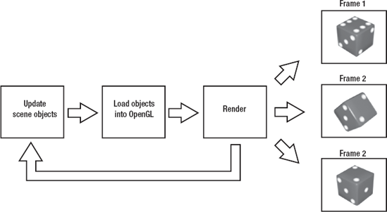
Figure 6.7. A basic render loop. Update the objects by changing the scene in some way, then load those objects into OpenGL, and then render. This creates the illusion of motion.
We are going to try to render our scene a whole bunch of times every second, and between each frame rendering, we will move our objects a bit. This is very similar to stop-motion animation.
Our job as programmers is to make code that updates the scene objects and loads them into OpenGL. All the rendering is done by OpenGL—in our case, by the CAEAGLLayer. The CAEAGLLayer works just like all the other Core Animation layers, and it needs a view to display it. In this chapter's example, we will make a wrapper for our CAEAGLLayer and call it the EAGLView.
This is a good time to open the sample code for this chapter. You have a project called BBOpenGLGameTemplate. If you build it and run it in the simulator, you should be able to tap the screen and have the box spin around (see Figure 6-8).
What you see here is the CAEAGLLayer, which is inside our EAGLView. We have added a single, square object to the scene. Every frame step, we are rotating the Technicolor-dream square by a few degrees and rerendering the entire scene. This will be the basis for our OpenGL game.
We have six objects in our template: the app delegate, scene controller, input view controller, scene objects, meshes, and EAGLView. Figure 6-9 provides a simple overview of all the objects and what they do.

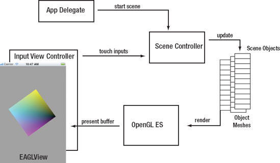
At the top, we have the app delegate. This sets up all our views and controllers. Once everything is ready, the delegate tells the scene controller to start the scene.
The scene controller is the main traffic control object. It handles the game loop. In the game loop, the scene controller first handles any touch inputs from the input view controller, then it updates all of the scene objects, and finally, it tells the objects to render themselves.
The scene objects represent all of the things we might want to render in our scene. They have all the basic state information, such as their position, rotation, and scale. They also contain a mesh object.
Mesh objects define how an object looks. The mesh's job is to load itself into the OpenGL engine.
At the end of the render loop, the OpenGL engine renders the scene and sends it to the EAGLView.
Our game design is nice and simple. Now let's look at the code. We are going to start with the most complicated bit first: the EAGLView.
The EAGLView is our handy wrapper for the CAEAGLLayer, which actually provides the low-level layer that renders our OpenGL scene into its own contents. It is important to understand how the EAGLView works, which is why we are looking at it first. It is a bit low level and technical, but don't let that worry you, as we won't need to change much of this low-level code. Astute readers may notice that our EAGLView object looks quite a bit like the Xcode OpenGL ES template, especially the older OS 2.x version. This EAGLView is based on that older template, with some minor modifications.
Note
In case you are wondering, EAGL is Apple's version of the EGL, an OpenGL specification for embedded graphics language, which is the interface between OpenGL and the iPhone hardware. The EGL specification is an even lower-level API that we don't really need to worry about, because the CAEAGLLayer takes care of all of that stuff for us.
Let's begin! Here's the very first method we see in the EAGLView.m file:
+ (Class)layerClass {
    return [CAEAGLLayer class];
 }
This tells the UIView that its main layer is going to be a CAEAGLLayer. The CAEAGLLayer is where the OpenGL content will be ultimately rendered. Without a CAEAGLLayer, we can't do any OpenGL, so it is pretty important. No matter what else you do with this template, you need to have a CAEAGLLayer to render your OpenGL content.
Next up is the initWithCoder: method. We are going to be specifying some of the esoteric CAEAGLLayer settings here. These settings define how the final image will look.
- (id)initWithFrame:(CGRect)rect {

    if ((self = [super initWithFrame:rect])) {
        // get the layer
        CAEAGLLayer *eaglLayer = (CAEAGLLayer *)self.layer;

        eaglLayer.opaque = YES;
        eaglLayer.drawableProperties = [NSDictionary dictionaryWithObjectsAndKeys:
        [NSNumber numberWithBool:NO], kEAGLDrawablePropertyRetainedBacking,
                   kEAGLColorFormatRGBA8, kEAGLDrawablePropertyColorFormat, nil];

        context = [[EAGLContext alloc] initWithAPI:kEAGLRenderingAPIOpenGLES1];

        if (!context || ![EAGLContext setCurrentContext:context]) {
            [self release];
            return nil;
        }
  }
    return self;
}
The first thing that we do is grab a reference to our CAEAGLLayer so we can set some basic parameters.
eaglLayer.opaque = YES;
This is basically a hint for the rendering system that we do not plan to have any transparent pixels in our layer content. This is a good habit to get into for any layers you are using that do not require transparency, but doubly so for CAEAGLLayer. You can use OpenGL to render a semitransparent scene and overlay that on top of some other UIKit views, but your game's performance will suffer greatly. The OpenGL rendering pipeline is a fickle beast, and on the iPhone, it performs optimally when it is the bottom layer. So, unless you have a very good reason, be sure to set the layer to be opaque.
Next up, we are going to set the drawing properties on our layer. These specify to OpenGL how the final output will behave.
eaglLayer.drawableProperties = [NSDictionary dictionaryWithObjectsAndKeys:
      [NSNumber numberWithBool:NO], kEAGLDrawablePropertyRetainedBacking,
      kEAGLColorFormatRGBA8, kEAGLDrawablePropertyColorFormat, nil];
We are specifying some things that affect the viewport—specifically, the memory that represents the viewport. kEAGLDrawablePropertyRetainedBacking refers to how the memory is handled after it has been displayed. Generally, we do not want to retain the backing buffer.
Wait, what is a backing buffer, and why don't we want to keep it around?
Think back to our basic render loop (Figure 6-7), and remember that we are rendering each frame individually and then showing it to the user. This means that we actually need to have a few screen-sized chunks of memory. We need a chunk of memory to render our new frames into, a chunk of memory that we can hand off to the CAEAGLLayer, and a chunk of memory that is used to store the frame the user is looking at right now. The chunk of memory that holds the current frame is the backing buffer for the CAEAGLLayer. That backing buffer is the final resting place for our pixels.
For the most part, you will always be rendering new frames and will have no need to access the current frame, so you tell the CAEAGLLayer that it does not need to keep it around any longer than absolutely necessary. Those pixels get pushed out to the display, and you never need to deal with them again. This helps with performance, so unless you have a very good reason to keep it, you should not retain the backing buffer.
Next, we need to specify the format of the final image. kEAGLDrawablePropertyColorFormat tells OpenGL how the memory is formatted. The default of RGBA8 means that our output buffer will be full quality, 1 byte of memory for red, green, blue, and alpha for each pixel. Now, we just told the renderer that our layer is opaque, so the alpha byte is kind of wasted here. Unfortunately, the only other option is kEAGLColorFormatRGB565. RGB565 means that we get 5 bits for red, 6 bits for green, and 5 bits for blue. What does this mean in terms of your scene? kEAGLColorFormatRGBA8 gives you millions of colors, whereas kEAGLColorFormatRGB565 gives you only tens of thousands of colors. Figure 6-10 is an example of the two different color formats. They look very similar, but the RGB565 format will tend to make chunkier gradients. We will leave it full quality for our game template.

Figure 6.10. kEAGLColorFormatRGBA8 (left) and kEAGLColorFormatRGB565 (right). RGB565 is slightly chunkier.
Tip
The only time I really notice the difference between kEAGLColorFormatRGBA8 and kEAGLColorFormatRGB565 is if my textures have very subtle gradients. My advice is to leave it at kEAGLColorFormatRGBA8 for now, and then later when you are optimizing, try it at kEAGLColorFormatRGB565 and see if the image quality suffers. I find that for most of my projects, I end up using kEAGLColorFormatRGB565, but it all depends on your specific game.
context = [[EAGLContext alloc] initWithAPI:kEAGLRenderingAPIOpenGLES1];
The context basically handles the rendering to the EAGLLayer. It is exactly like a CGContextRef in Quartz 2D. It is important to note the API constant we are providing: kEAGLRenderingAPIOpenGLES1. This tells the context that we are going to be using OpenGL ES 1.1 style commands and structures. With the introduction of the new iPhone 3GS, we can now take advantage of OpenGL ES 2.0 features on that specific device. OpenGL ES 2.0 is quite a bit different from OpenGL ES 1.1, and it is difficult to get a good handle on the 2.0 API without a firm grasp of the basics of OpenGL, so we are going to stick mainly to the 1.1 API. This will give you a good understanding of OpenGL basics, and then the step to the 2.0 API will be a small one.
Tip
If you start a new project with Xcode's OpenGL ES template, you can get a nice starting point for OpenGL ES 2.0 applications, and also see some of the differences between OpenGL ES 1.1 and OpenGL ES 2.0. There are a few other little things that you may want to do if you are going to be moving up to OpenGL ES 2.0, and I will note them as they come up. If you make it through these three introductory chapters on OpenGL ES 1.1, you will be in a good position to take the next step into the world of shaders and programmable pipelines.
The next method in EAGLView.m we are going to look at is createFrameBuffer. Frame buffers are similar to the backing buffer discussed in the previous section. They are the chunks of memory that OpenGL needs to be able to do its work.
- (BOOL)createFramebuffer {
    glGenFramebuffersOES(1, &viewFramebuffer);
    glGenRenderbuffersOES(1, &viewRenderbuffer);

    glBindFramebufferOES(GL_FRAMEBUFFER_OES, viewFramebuffer);
    glBindRenderbufferOES(GL_RENDERBUFFER_OES, viewRenderbuffer);

    [context renderbufferStorage:GL_RENDERBUFFER_OES fromDrawable:(CAEAGLLayer*)self.layer];
    glFramebufferRenderbufferOES(GL_FRAMEBUFFER_OES, GL_COLOR_ATTACHMENT0_OES, GL_RENDERBUFFER_OES, viewRenderbuffer);
glGetRenderbufferParameterivOES(GL_RENDERBUFFER_OES, GL_RENDERBUFFER_WIDTH_OES, &backingWidth);
glGetRenderbufferParameterivOES(GL_RENDERBUFFER_OES, GL_RENDERBUFFER_HEIGHT_OES, &backingHeight);
if (USE_DEPTH_BUFFER) {
glGenRenderbuffersOES(1, &depthRenderbuffer);
glBindRenderbufferOES(GL_RENDERBUFFER_OES, depthRenderbuffer);
glRenderbufferStorageOES(GL_RENDERBUFFER_OES, GL_DEPTH_COMPONENT16_OES, backingWidth, backingHeight);
glFramebufferRenderbufferOES(GL_FRAMEBUFFER_OES, GL_DEPTH_ATTACHMENT_OES, GL_RENDERBUFFER_OES, depthRenderbuffer);
}
if(glCheckFramebufferStatusOES(GL_FRAMEBUFFER_OES) != GL_FRAMEBUFFER_COMPLETE_OES) {
NSLog(@"failed to make complete framebuffer object %x", glCheckFramebufferStatusOES(GL_FRAMEBUFFER_OES));
return NO;
}
return YES;
}The important concepts to take away from this method are the three basic buffers: the frame buffer, the render buffer, and the depth buffer. The other side effect of this method is that the instance variables backingWidth and backingHeight are set based on the size of the view. These are just the width and height of the view bounds in pixels.
The frame, render, and depth buffers are all instance variables. The frame buffer is basically the big chunk of memory that will be used to hold the various bits of data needed to render a single frame. The render buffer is where the frame will be rendered before it is copied into the CAEAGLLayer backing buffer and ultimately ends up on the display. The depth buffer requires a bit more explanation.
Notice the if (USE_DEPTH_BUFFER) block in the createFrameBuffer method. Way up at the top of the EAGLView.m file, you see this define:
#define USE_DEPTH_BUFFER 0
For the template code, we are not going to use the depth buffer. If you want to use the depth buffer, just change the define's 0 to a 1.
OK, so that's how you turn on a depth buffer. But what is it?
OpenGL, like most every other graphics display API, uses what is known as the painter's algorithm to draw things to the screen. This means that the first thing that you send to the engine gets drawn first, and the second thing will get drawn second; if they occupy the same screen space, then the second thing will be on top of the first thing. This makes a great deal of sense, and it is also how a painter would paint a picture. However, we have a problem once we move into a 3D space. What if the second object drawn is actually farther away than the first object? Well, if you do not use the depth buffer, then the second object will get drawn on top of the first object, even though it should technically be behind it. This can look very odd, especially if the scene is fairly complex (see Figure 6-11). How do you fix it? One solution is to make sure that you always draw things that are farther away from the camera first. Another option is to let the engine figure out what is in front, and that is what the depth buffer is for.

Figure 6.11. Sometimes you need to use the depth buffer to sort out more complicated rendering situations.
When you set USE_DEPTH_BUFFER to 1, this method will also generate a depth buffer that the engine can use for depth sorting. (To use depth sorting, you also need to turn it on in the engine like so: glEnable(GL_DEPTH_TEST).) When depth sorting is active, the engine will take all your draw calls and sort the various vertexes based on how far away they are from the camera, and render them in the proper order.
How great! Just turn on the depth sort, make sure there is a depth buffer, and the engine will do all this hard sorting for you! Well, unfortunately, nothing comes without a price. In this case, the price is performance. If you can architect your code in such a way that you can guarantee that the objects will get drawn to the screen in the correct order, then you will get better performance out of your system. In our example, we will be dealing mostly with 2D scenes, so it will be fairly easy to keep everything in the right order, and we won't need to use the depth buffer.
The next method, layoutSubviews, is responsible for creating the frame buffers and setting up the view for the first time.
- (void)layoutSubviews
{
    [EAGLContext setCurrentContext:context];
    [self destroyFramebuffer];
    [self createFramebuffer];
    [self setupView];
}
The first thing we do is set the EAGLContext. We got the context way back in the init method. Next, we destroy the frame buffer if there is one, which allows us to make a new one.
- (void)destroyFramebuffer {
    glDeleteFramebuffersOES(1, &viewFramebuffer);
    viewFramebuffer = 0;
    glDeleteRenderbuffersOES(1, &viewRenderbuffer);
    viewRenderbuffer = 0;

    if(depthRenderbuffer) {
        glDeleteRenderbuffersOES(1, &depthRenderbuffer);
        depthRenderbuffer = 0;
    }
}
This is the exact opposite of the createFrameBuffer method. We are cleaning up our buffers. Just destroy each buffer and set the reference to 0.
Our next stop is the setupView method, where all the interesting stuff starts to happen.
Near the beginning of the chapter, I talked about the idea of a table with some objects, a camera, a lens, and a camera position. In order to see into our 3D world, we will need the camera and the lens. In OpenGL, these are called the viewport and the projection matrix.
With that in mind, let's have a look at the setupView method in the EAGLView.m file:
- (void)setupView
{
    // set up the window that we will view the scene through
    glViewport(0, 0, backingWidth, backingHeight);

    // switch to the projection matrix and set up our 'camera lens'
    glMatrixMode(GL_PROJECTION);
    glLoadIdentity();
    glOrthof(−1.0f, 1.0f, −1.5f, 1.5f, −1.0f, 1.0f);

    // switch to model mode and set our background color
    glMatrixMode(GL_MODELVIEW);
    glClearColor(0.5f, 0.5f, 0.5f, 1.0f);
}
This looks like a very simple method, and it is, but it covers a few concepts that are very important.
The viewport is the place where the final image is ultimately displayed to the user. All we really need to specify about the viewport is how big it is. We do that in the first line of the method:
// set up the window that we will view the scene through
    glViewport(0, 0, backingWidth, backingHeight);
This is simply defining the rectangle that will be the viewport. For our purposes, we will have it fill the entire view, so we tell it to start at 0,0 and use the backing width and height for its own size. This seems a bit redundant though. Why do we need to define the viewport if we already have a view size defined, and we have already defined the size of our frame and render buffers?
Remember how we talked about OpenGL being stateful? Well, that means that once you set some values into the engine, they stay set until you decide to change them. The viewport is one of those things. If you wanted to render two separate scenes to the same frame, you could set the viewport to the left half of the view and draw some objects, and then set the viewport to the right half of the view and draw some other objects. When you rendered that scene, it would look like a split screen. For our purposes, we just want to render a single scene, so we set it to take up the whole view.
Next up is the projection matrix:
// switch to the projection matrix and set up our 'camera lens'
    glMatrixMode(GL_PROJECTION);
    glLoadIdentity();
    glOrthof(−1.0f, 1.0f, −1.5f, 1.5f, −1.0f, 1.0f);
The first line here is a very important one. By calling glMatrixMode(), we are telling OpenGL to change modes to GL_PROJECTION. So now any OpenGL function calls will apply to the projection matrix.
The next thing we do is call glLoadIdentity(). This clears whatever might have been in the projection matrix and sets it back to the identity matrix. The identity matrix is a matrix that, when multiplied by any other matrix, makes no changes. It is the blank slate of matrixes.
But what is the projection matrix? You may recall that I described the projection matrix as similar to the lens of the camera through which you are viewing your scene. This is a fairly apt analogy, except that the projection matrix can do so many more things than any camera lens can do.
There are two main modes of the projection matrix: perspective mode and orthographic mode. In perspective mode, your models are foreshortened. The farther away they are from the camera, the smaller they get. In orthographic mode, you do not have this property, so no matter how far something is from the camera, it will always render the same size. You can see the difference in Figure 6-12.
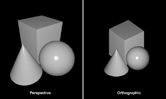
Figure 6.12. Perspective mode is more how we see things with the naked eye (or though a camera lens). Orthographic mode is good for 2D work as well as technical 3D work, where being able to tell the relative sizes of objects is necessary.
For our template, we will use orthographic mode.
glOrthof(−1.0f, 1.0f, −1.5f, 1.5f, −1.0f, 1.0f);
The orthographic mode defines a simple box shape that is our visible space. We specify the leftmost value, the rightmost value, the upper bounds, the lower bounds, and the near and far bounds.
glOrthof(left, right, bottom, top, near, far);
The resulting box is what is visible on screen. Any scene objects that are inside that volume will be rendered. This is a simple way of doing 2D work. This way, any objects we place on the xy plane at z = 0 will be rendered—well, as long as the objects do not stray too far away from xy = 0,0.
Orthographic mode does not fit neatly into terms of real-world cameras and clever analogies. It is very hard to take a photograph that is truly orthographic. The closest analogy is a very long lens shooting subjects that are very far away. Luckily for us, we have no similar limitations in the virtual world!
Slightly more complicated in OpenGL, but easier to imagine, is the perspective mode. The perspective mode renders images the way that you might actually see them through a camera lens. The downside is that it can be a bit complicated to set up. In this mode, you are defining a view frustrum. A view frustrum is the shape of the field of view of a lens. This is sort of a truncated pyramid shape, and it is defined in the same way as the orthographic viewing volume.
glFrustrum(left, right, bottom, top, near, far);
However, you do not get a nice box shape, but something more like Figure 6-13.
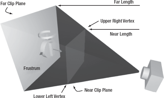
Figure 6.13. A perspective mode view frustrum. Anything that is in the frustrum between the near plane and the far plane will be rendered.
The lower left vertex is defined by the values (left, bottom, -near), and the upper right is defined by (right, top, -near). The shape of the frustrum, roughly equivalent to the focal length of a camera lens, is defined by the relationship between the near clip plane and the far clip plane. This is a simple model, but in practice, it is quite hard to use.
A very handy utility that comes with the desktop version of OpenGL is called gluPerspective(). It allows you to specify the view frustrum as an aspect ratio and a viewing angle, which is much easier for most people to do. Unfortunately, that handy function is not part of the smaller OpenGL ES API. However, gluPerspective() is so useful that it is worthwhile to rewrite this function. You can find this in the EAGLView.m file:
-(void)perspectiveFovY:(GLfloat)fovY aspect:(GLfloat)aspect zNear:(GLfloat)zNear zFar:(GLfloat)zFar
{
    const GLfloat pi = 3.1415926;

    // - halfWidth = left, halfWidth = right
    // - halfHeight = bottom, halfHeight = top

    GLfloat halfWidth, halfHeight;
    //    use the fovy and some trig to find the height
    halfHeight = tan( (fovY / 2) / 180 * pi ) * zNear;

    //    use the height and the aspect ratio to calc the width
    halfWidth = halfHeight * aspect;
// now call glFrustum with our new values
glFrustumf( -halfWidth, halfWidth, -halfHeight, halfHeight, zNear, zFar );
}Note
Any functions you come across in OpenGL code that start with glu or glut are not part of the OpenGL ES specification. You will need to implement them yourself.
Here, we are just taking some easier-to-handle values and then calculating the vertex values that glFrustrum() requires. fovY is the vertical angle of the field of view. The aspect ratio is the width of the view over the height. zNear and zFar are the z positions of the near and far clipping planes.
So, the projection matrix defines what slice of 3D space we will actually see in our rendering, and how those objects will be drawn.
Warning
Be sure you are in the right mode when you are setting or changing the projection matrix! Don't forget to go into glMatrixMode(GL_PROJECTION) before making calls to glFrustrum() or glOrtho().
Whether you're using the perspective or orthographic mode, make sure that your near and far plane are set properly. A common mistake is to not realize that any objects or vertexes that fall outside the view frustrum will not be rendered. You may find that your camera and objects are in the right place, but nothing is rendering. Check to make sure that your objects are not closer than your near clipping plane or farther than your far clipping plane. Unlike with real cameras, if you build a brick wall between the camera and your model, if it is between the camera and the near clip plane, it will not show up. Similarly, you might build a complex and lovely mountain range with a setting sun to show behind your model, but if it is farther away than your far clip plane, you will never see it.
We have gone off on a few tangents, but we are still talking about the setupView method in the EAGLView object. Let's look at the last two lines:
// switch to model mode and set our background color
    glMatrixMode(GL_MODELVIEW);
    glClearColor(0.5f, 0.5f, 0.5f, 1.0f);
Again, you see the glMatrixMode() call. This time, we are telling OpenGL that any further calls need to apply to the model view matrix. In this case, that call is to set the clear color. The clear color is basically the background color of the view. When you wipe your view clean to get ready to render the next frame, this is the color you get.
We are nearly finished with the EAGLView. Our final methods are beginDraw and finishDraw. These are the beginning and the end of our rendering loop. We call beginDraw, and then we make all of our OpenGL calls to build our scene. Finally, we call finishDraw, which tells OpenGL to render our scene to the display.
-(void)beginDraw
{
    // make sure that you are drawing to the current context
    [EAGLContext setCurrentContext:context];
    glBindFramebufferOES(GL_FRAMEBUFFER_OES, viewFramebuffer);

    // make sure we are in model matrix mode and clear the frame
    glMatrixMode(GL_MODELVIEW);
    glClear(GL_COLOR_BUFFER_BIT);
    // set a clean transform
    glLoadIdentity();
}
The first thing we do is set the context. This informs the hardware that our EAGLView is going to be doing the rendering for the time being. Next, we bind the frame buffer. We do quite a bit of binding in OpenGL, but all that really means is that we tell OpenGL to use our frame buffer to draw into. Binding is simply making a connection between OpenGL and some bit of data or memory space that you control.
The next bit looks familiar:
glMatrixMode(GL_MODELVIEW);
    glClear(GL_COLOR_BUFFER_BIT);
    // set a clean transform
    glLoadIdentity();
You have already seen a few of these functions. glMatrixMode() tells OpenGL that we are going to be dealing with the model matrix; that is, we are going to be drawing objects. The call to glClear() cleans the view with whatever color we have defined for the clear color. Finally, we load the identity matrix, which we know is the clean slate of matrixes.
So, beginDraw basically sets us up a blank page to work on. The finishDraw method does the opposite.
-(void)finishDraw
{
    glBindRenderbufferOES(GL_RENDERBUFFER_OES, viewRenderbuffer);
    [context presentRenderbuffer:GL_RENDERBUFFER_OES];
}
finishDraw finalizes the draw process by handing the render buffer over to the context to push to the screen. This is where the actual rendering happens. After this method returns, you will have a new frame on the display.
Now you understand the basics of how the OpenGL scene is rendered out to the display, and you know how to set up the CAEAGLLayer. But we still haven't drawn anything yet! Next, we'll look at the scene objects and meshes, and how to actually get objects into OpenGL.
You have seen the EAGLView now, up close and personal. Now we are going to explore how to actually send information about your objects into OpenGL. The two building blocks for this are the scene object and the mesh object.
The scene object holds all the state for your object, and the mesh object holds the information for how your object looks. Let's begin by looking at the basic functionality of each of these objects.
The scene object has three main methods: awake, update, and render. These can be seen in the BBSceneObject.m file. I will move pretty quickly through them here, and provide more details in the next sections. The intent is to give you the big picture before we get into the specifics.
First up is the awake method:
static CGFloat spinnySquareVertices[8] = {
−0.5f, −0.5f,
0.5f,  −0.5f,
−0.5f,  0.5f,
0.5f,   0.5f,
};

static CGFloat spinnySquareColors[16] = {
1.0, 1.0,   0, 1.0,
0,   1.0, 1.0, 1.0,
0,     0,   0,   0,
1.0,   0, 1.0, 1.0,
};

-(void)awake
{
    mesh = [[BBMesh alloc] initWithVertexes:spinnySquareVertices
           vertexCount:4
           vertexSize:2
           renderStyle:GL_TRIANGLE_STRIP];
    mesh.colors = spinnySquareColors;
    mesh.colorSize = 4;
}
The awake method is allocating a mesh object, and sending in those two ugly lists of numbers: spinnySquareVertices and spinnySquareColors, along with the OpenGL constant GL_TRIANGLE_STRIP. We will look at all of this in more detail when we get to the mesh, but for now, just remember that the mesh is holding all of the data that tells us what the object looks like.
Next, let's look at the update method:
-(void)update
{
    // check the inputs, have we gotten a touch down?
    NSSet * touches = [[BBSceneController sharedSceneController].inputController touchEvents];
    for (UITouch * touch in [touches allObjects]) {
        // then we toggle our active state
        if (touch.phase == UITouchPhaseEnded) {
            active = !active;
        }
    }
    // if we are currently active, we will update our zRotation by 3 degrees
    if (active)    zRotation += 3.0;
}
This simple update method checks to see if there has been any touch activity, and if so, it toggles the active flag. If we are active, then increase zRotation by 3. This gets called every frame, and if we have tapped the screen and activated the object, then it will spin at 3 degrees per frame.
Note
Remember that we are spinning around the z axis. The z axis is like an arrow pointing straight out of the screen, which is why the square looks like it is pivoting around its center.
Finally, the render method in the scene object looks like this:
// called once every frame
-(void)render
{
    // clear the matrix
    glPushMatrix();
    glLoadIdentity();

    // move to my position
    glTranslatef(x, y, z);

    // rotate
    glRotatef(xRotation, 1.0f, 0.0f, 0.0f);
    glRotatef(yRotation, 0.0f, 1.0f, 0.0f);
    glRotatef(zRotation, 0.0f, 0.0f, 1.0f);

    //scale
    glScalef(xScale, yScale, zScale);

    [mesh render];

    //restore the matrix
    glPopMatrix();
}
The render method provides a clean slate to draw itself onto. It also saves whatever state the engine was in before it got to this object. It then moves to where it is meant to be drawing, rotates to the correct orientation, and scales itself to the desired size. Then it calls the [mesh render] method, which will actually build our object. Finally, we restore the saved state.
Basically, the scene object render method controls where your object will be drawn, what orientation it is in, and how big it is.
Now, let's look at the mesh render method in the BBMesh.m file:
// called once every frame
-(void)render
{
    // load arrays into the engine
    glVertexPointer(vertexSize, GL_FLOAT, 0, vertexes);
    glEnableClientState(GL_VERTEX_ARRAY);
    glColorPointer(colorSize, GL_FLOAT, 0, colors);
    glEnableClientState(GL_COLOR_ARRAY);

    //render
    glDrawArrays(renderStyle, 0, vertexCount);
}
We are close to having all the pieces to the puzzle. You can see we are doing some things with the arrays of ugly numbers passed in earlier. This is defining the shape and color of our object to OpenGL. Finally, we call glDrawArrays(), which sounds suspiciously like it should actually draw something!
OK, let's step back and have a look at the rendering. We start in the scene object render method and we do this:
Save the state of the engine.
Clean the slate in preparation for drawing.
Move our object to its position in space.
Rotate our object to its orientation in space.
Scale our object to its size.
Then, in our mesh object, we do the following:
Define our object shape and color.
Draw our object.
And back in the scene object, we do this:
Restore the saved state.
This is the basic technique for drawing an object in OpenGL. Let's look at each bit in detail.
As you now know, OpenGL is a stateful system. You may recall that back in our beginDraw method in the EAGLView, the last thing we did was to set the model matrix as the current matrix. This means that all the calls we are making in these render methods are affecting the model matrix.
Remember that the model matrix state defines things like position and rotation. Before this scene object's render method is called, some other process might have translated, rotated, and scaled. We have no idea if this has happened, so we want to make sure that our object shows up in the correct spot. To do this, we make the following call:
// clear the matrix
    glPushMatrix();
    glLoadIdentity();
glPushMatrix() takes the current state of the model matrix and pushes a copy of it onto a stack, effectively saving it for later. You have seen glLoadIdentity() a few times now, and you know that it clears the current matrix. This leaves us with a fresh matrix to start with.
We then go on to put all of our object's data into the matrix and render it. But the last thing we want to do is restore the saved matrix, so we make the following call:
//restore the matrix
    glPopMatrix();
This takes whatever matrix was at the top of the stack—in this case, the one we saved just a moment ago—and makes it the current matrix. This means that whatever is happening to the engine outside our object, we won't change it.
We talked earlier about matrixes and that they specify a position, rotation, and scale. But how do we tell OpenGL about these things? Recall from the beginning of the chapter the discussion of the three axes, and rotating and scaling things. These are just the OpenGL-specific methods for setting those values. There are actually several different ways to apply a matrix to your model, and we will cover a few of them in the chapters to come. Here, we'll look at the simplest method of moving your model around in space: using glTranslate(), glRotate(), and glScale().
glTranslate() is a simple method. It takes in x, y, and z values, and moves your model the specified amounts in the specified directions. The only thing to remember is that glTranslate() moves your model relative to where it currently resides. Consider the following call:
glTranslatef( 1.0, 1.0, 1.0);
This method call will not move your model to 1,1,1; instead, it will move it one unit in x, one unit in y, and one unit in z from wherever it is now.
In our case, we have cleared the matrix with a glLoadIdentity(), so our objects start at 0,0,0. Later, when we start parenting objects together, it will become more important to remember that glTranslate() is always relative to the current matrix position.
You might be wondering about that f on the end of the preceding function call. Most all the functions in OpenGL that take numerical values can be called with more than one data type. You will see suffixes like vi, fv, f, and x—just to name a few. There are many good reasons for sending your data to OpenGL as a float vector (fv, which is just an array of floats), but mostly they have to do with wringing every last bit of performance out of the system. We will touch on a few of these in the chapters to come, but for the most part, I am going to stick to the float (f) versions of most functions to keep things simple.
glScale() behaves exactly like glTranslate(). You pass in x, y, and z values, and it will scale your model by the specified amounts in the specified directions. Again, this is fairly straightforward.
The same caveats apply as those for glTranslate(): glScale() applies the scale multipliers to what you already have. The following call will make your model twice as tall without affecting the other axes:
glScale( 1.0, 2.0, 1.0);
The only gotcha with glScale() is that it is a multiplier, so if you don't want it to affect one of your axes, then pass in 1.0.
Finally, we have glRotate(). glRotate() takes four values: the first is the rotation angle in degrees, and the next three specify a vector to rotate around. The simplest of these is to rotate around the unit vectors, like so:
// rotate
    glRotatef(xRotation, 1.0f, 0.0f, 0.0f);
    glRotatef(yRotation, 0.0f, 1.0f, 0.0f);
    glRotatef(zRotation, 0.0f, 0.0f, 1.0f);
Earlier, I mentioned compound rotations. That is what we are doing here. The glRotate command can rotate your object around any arbitrary vector, but to keep things simple, we are doing three separate rotations using the major axes as the vectors.
This is a good time for a minor diversion to talk about unit vectors. In our first rotation in the preceding example, we are rotating some amount around the vector 1,0,0. This is a unit vector. A unit vector is any vector whose length is 1. This unit vector is a special one, in that all of its length is in one axis. This means that this unit vector is equivalent to the x axis. So in the preceding code, we first rotate around the x axis, then the y axis, and finally the z axis.
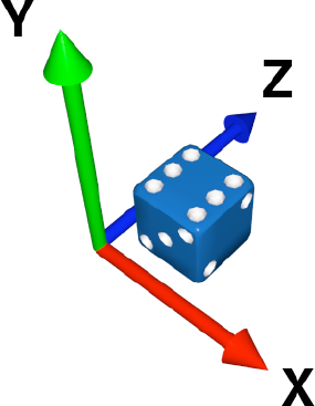
Rotations can be confusing, and it is worth repeating a figure from earlier in the book, which I will now call Figure 6-14. Breaking down your rotations into angles about the main axes is a decent way to keep the rotations simple. If you aren't doing complex things, then this is a fine way to deal with rotations.
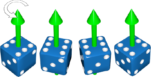
Figure 6.14. A reminder about how rotations work. We pick an axis, then we use that axis as a pivot to spin our object.
Note
The art and mathematics behind rotating things in 3D space, as well as the specification of said rotations, are actually very complex. I could easily spend a whole chapter just talking about rotations—possibly even a whole book. However, I don't have that kind of space, so we will keep it very simple.
It is important to note that if you do the exact same rotations, but in a different order, then your model will end up in very different orientations. In Figure 6-15, we start with our die and we rotate it by 90 degrees around the y axis. Then we rotate it 90 degrees around the z axis. Excellent, we rolled a 4! But if we take those exact same rotations, but apply them in the reverse order, our die is in the wrong orientation, and our 4 is now a 5. So, remember that the order of your rotations matter.

Figure 6.15. If we apply the same rotations, but in a different order, we do not get the same resulting orientation.
In fact, any time you are adjusting any matrix with glRotate(), glTranslate(), and glScale(), the order is always important. If you perform the functions in one order, you will almost never get the same result if you apply them in another order.
You now know how to move our object, set its orientation, and set its size. But how do you define its shape? You may have figured this out by the name of the object: mesh. We will use a mesh of vertexes to define the shape of our object.
A vertex is simply a single point in space. This single point is defined by its x, y, and z coordinates. However, in order to draw a vertex, we need to know at least one more thing about it: its color.
Recall our two ugly lists of numbers from BBSceneObject.m. We took those arrays and loaded them into the mesh object as the vertex array and the color array.
static CGFloat spinnySquareVertices[8] = {
−0.5f, −0.5f,
0.5f,  −0.5f,
−0.5f,  0.5f,
0.5f,   0.5f,
};

static CGFloat spinnySquareColors[16] = {
1.0, 1.0,   0, 1.0,
0, 1.0, 1.0, 1.0, 0, 0, 0, 0, 1.0, 0, 1.0, 1.0, };
Also recall the mesh render method from BBMesh.h:
// load arrays into the engine
    glVertexPointer(vertexSize, GL_FLOAT, 0, vertexes);
    glEnableClientState(GL_VERTEX_ARRAY);
    glColorPointer(colorSize, GL_FLOAT, 0, colors);
    glEnableClientState(GL_COLOR_ARRAY);
How does this work? For each vertex you want to send to OpenGL, you need to tell it how many coordinates and what kind of values they are. So, in our template we are calling this:
glVertexPointer(vertexSize, GL_FLOAT, 0, vertexes);
The first number is the size of each vertex. In this case, we are sending only x and y, so our size is 2. In OpenGL, if you specify only two vertexes, they are always the x and y vertexes, and the z is considered to be 0. Later on, we will be doing 3D stuff, and we will be including the z value.
The next value is telling OpenGL what type of value to expect—in this case, floats. The size and the variable type allow OpenGL to quickly and easily get to any vertex in your array. The third value is the index from where you want to start drawing. If you have a huge array full of vertexes, then you might not want to start right at the beginning, but instead draw some subset of vertexes. In our case, we are starting at index 0, or the beginning. Lastly, we pass in the actual vertex data, as a C-style array.
For colors, we are doing basically the same thing:
glColorPointer(colorSize, GL_FLOAT, 0, colors);
Here, the size is 4, because we have red, green, blue, and alpha coordinates for each color. Looking at the arrays of numbers, you can see that our vertex array is in groups of two, and the color array is in groups of four. This makes it easy to visualize which colors go with which vertexes. Our first vertex is at x,y,z = −0.5,−0.5,0.0, and the color is RGBA = 1.0, 1.0, 0.0, 1.0, which is yellow.
We are also using these cryptic enable client state calls:
glEnableClientState(GL_VERTEX_ARRAY);
    glEnableClientState(GL_COLOR_ARRAY);
These inform the engine which arrays we are bothering to define. Vertex position and color are not the only arrays of information that we could be passing to OpenGL; there are quite a few different types of information we could be sending into the engine. Here, we are passing only vertex and color, so we also need a way to tell OpenGL which types of information we are providing it, and glEnableClientState() is how that's done.
Regarding the color array, when you specify a color change between one vertex and the next, OpenGL will render a smooth gradient between those two vertexes by default. If you are rendering triangles with three different colors on the three corners, it will blend them all together. This is how the spinning square gets its Technicolor appearance.
Once the data is loaded into the renderer, and you have enabled the bits you are interested in, you need to tell OpenGL how you want all that data converted into images. Basically, the renderer will go through the vertex data one vertex at a time and build an image. You have the choice of whether you want to simply connect all the vertexes with lines or use the vertexes to create triangles.
In OpenGL ES, you have seven choices of how you want your vertex data turned into images, You can see in Figure 6-16 that each rendering style will produce very different results given the input vertexes, so it is up to you to pick the one that suits your geometry.

The three styles that draw triangles (GL_TRIANGLES, GL_TRIANGLE_STRIP, and GL_TRIANGLE_FAN) mean that OpenGL will fill each triangle with whatever colors are specified for the three vertexes that make up that triangle.
glDrawArrays(GL_TRIANGLE_STRIP, 0, 4);
In our template code, we are using the GL_TRIANGLE_STRIP style. The next value in that method is the index of the vertex array that we want to start with, and the last value is the number of vertexes that we want to render in this draw call.
Our vertex array is the array of reference, and it has a size of two 2. We have also activated and supplied a color array, with a size of 4. Then we said we wanted to render these arrays as a triangle strip. That's simple enough. But what is going on here?

You can see in Figure 6-17 that for each vertex, the engine grabs values from the array based on the size—in this case, two values. It assigns those to x and y, and makes z = 0 by default.
Since we supplied a color array also, the engine knows to go to that array, and get out a color based on the size. In this case, it grabs four values off the array and builds a color from them. Once it has all this information for that single vertex, it moves onto the next vertex. Since we have specified to draw them in a triangle strip, it will collect three vertexes and then render that triangle, smoothly blending the colors of the vertexes.
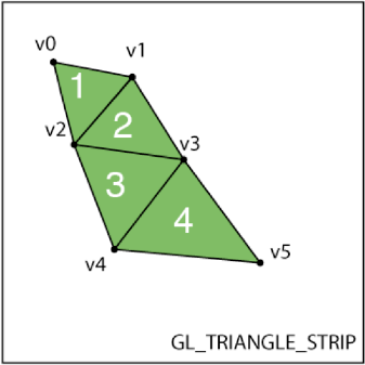
Figure 6.18. The triangles in a strip share vertexes. Triangle 1 is made of v0, v1, v2. Triangle 2 is made of v2, v1, v3.
To complete our square, the engine drops the first vertex but keeps the second and third. This is because we specified GL_TRIANGLE_STRIP as the rendering style. In Figure 6-18, you can see how the vertexes are reused in a triangle strip, and why we need only four vertexes, even though we are drawing two triangles.
So the crux of this is that in order to draw anything, we need to tell the engine three things:
The vertex positions and all other information about each vertex, in the form of ordered lists of values
Which types of information we are giving to OpenGL, using
glEnableClientState()Which rendering style to use when drawing those vertexes
This is the foundation of all drawing in OpenGL ES. Once you wrap your brain around this seemingly convoluted way to draw, everything you learn in the following chapters will come very easily.
Well, there is one last thing that can be quite confusing. We have two sets of positions. The vertex array specifies an x, y, and z value for every point in our object. And we also specify an x, y, and z translation for the scene object. What is that about?
Way back at the beginning of the chapter, we talked about matrixes and how they can be multiplied together. There was discussion of a house matrix multiplied by a table matrix and so on. Well, the way this actually works is that each and every point you pass into OpenGL as part of a vertex array gets multiplied by the current model matrix. When you multiply a point with a matrix, what you get is a new point that has been transformed by whatever translation, rotation, and scale that the matrix specified. This is why we specified our scene object's translation, rotation, and scale before we had the mesh render the vertexes. Every point in our vertex arrays is transformed into this new position by the model matrix.
By now, you should be beginning to see the power that this gives you as a developer. You can create an arbitrarily complicated mesh of points that represents your object, like a spaceship. And all you need to do to render it from any crazy angle is to pass in a few translation, rotation, and scale parameters. What if you want to draw two spaceships? Render one, change the model matrix to a new position and orientation, and then render the other one.
All of this code infrastructure can seem very daunting, but once it is in place, you will have so much fun you won't know how you lived without OpenGL.
So far, you have learned about how to set up the OpenGL system to render to the screen. You have seen how to define objects, move them around, and render them. Now it's time to look at the glue that holds this game code together: the game loop.
In Core Animation, you can just tell a layer, "Move over there, over 2 seconds," and it does all the work for you. In OpenGL, we need to handle all the motion ourselves. In order to do this, we need to be constantly updating the objects and rendering them so that they animate properly. To animate the objects, we need to render a whole bunch of new frames every second, and for this, we need a timer. However, it's not quite as simple as that.
On the iPhone hardware, the screen refresh rate is 60 Hz. The OpenGL render engine can swap the buffers to the screen only 60 times a second. On top of that, the buffer-swapping code will wait for the screen to be completely refreshed before it swaps to the next buffer. This means that 60 fps is the highest frame rate you can achieve on the iPhone. If you can get your code to finish all the processing for each frame in under 1/60 second, your animations will be very smooth.
The other effect of the rendering being tied to the hardware refresh rate is that if your code takes just slightly longer than 1/60 second and you miss the refresh window, you will need to wait until the next one before your buffer will be displayed. This means that in reality, you can get only a few frame rates out of the renderer: 60 fps, 30 fps (60/2), 20 fps (60/3), 15 fps (60/4), and so on.
So, there are actually two separate frame rates in your code: the rate at which your game code executes and the rate at which the user actually sees the frames. Practically speaking, if your code is executing slightly slower than 60 fps (say 58 fps), you will be getting only 30 fps actual performance from the renderer (because you are just missing every other screen refresh). This is not necessarily a bad thing, as long as the actual achieved frame rate is consistent. However, if your code is very close to the cutoff rate (i.e. it slides between 59 fps and 61 fps), then you will be moving from 60 fps actual render performance to 30 fps and back again, which can cause stuttering and jittery animation. It is better to have smooth animation at 30 fps than to have stuttery animation that is sometimes 60 fps and sometimes 30 fps. Therefore, it is a good idea to measure your game loop performance and pick the appropriate animation interval so that you are never dropping below your desired frame rate.
There are a few ways to approach this timer issue. The simplest is to simply use an NSTimer that calls your game loop every 1/60 second. The upside of this method is that it is very easy. The downside is that if you take too long to render, you can get out of sync with the display refresh rate, and your frames per second will suffer.
A more complicated approach is to simply run the game loop as fast as possible. As soon as you are finished rendering a frame, you start rendering the next—you don't wait for any timers to fire or anything. This is generally how high-end 3D games work. This method allows you to squeeze every last bit of performance out of your graphics hardware. However, since the iPhone graphics are pegged at 60 Hz, generating frames faster than that will not make your game any smoother. The only thing it will do is drain your battery faster.
Finally, in iPhone OS 3.1, Apple introduced the idea of a display link. A display link is a hardware-triggered callback that will call a specified method on your object every time the screen refreshes. This object is called the CADisplayLink. Setting it up is very similar to setting up a timer. If you were to use a display link for your code, it might look a bit like this:
displayLink = [CADisplayLink displayLinkWithTarget:self selector:@selector(gameLoop)];
[displayLink setFrameInterval:animationFrameInterval];
[displayLink addToRunLoop:[NSRunLoop currentRunLoop] forMode:NSDefaultRunLoopMode];
This will call the gameLoop method every 1/60 second, every time the screen refreshes.
We are not going to use the display link for the example in this chapter, because it is for OS 3.1 only, and we want to make sure this code will run on any old iPhone. Also, we are not doing anything that is very processor-heavy, so we don't really need to worry so much about frames per second until we get into the 3D stuff in the next chapters.
In our template, both the game loop and the timer are the responsibility of the scene controller. Here is our timer start code, from the BBSceneController file:
- (void)startAnimation
{
    self.animationTimer = [NSTimer scheduledTimerWithTimeInterval:animationInterval
          target:self selector:@selector(gameLoop) userInfo:nil repeats:YES];
}
It's very simple. There are a few other methods in there to deal with changing the timer and stopping the timer, which are all pretty self-explanatory.
This brings us to the game loop, in the same file:
- (void)gameLoop
{
    // apply our inputs to the objects in the scene
    [self updateModel];
    // send our objects to the renderer
    [self renderScene];
}
Every 1/60 second, we update the model, and then we render. It's that simple. Let's take a closer look at the updateModel and renderScene methods.
- (void)updateModel
{
    // simply call 'update' on all our scene objects
    [sceneObjects makeObjectsPerformSelector:@selector(update)];
    // be sure to clear the events
    [inputController clearEvents];
}
You may recall from our scene objects that the update method checked to see if there was a tap, and also incremented the rotation. Later on, our update methods will become more complicated, but this controller code will stay the same.
The last line calls [inputController clearEvents]. We will talk about the input controller next, but this is basically just clearing out any touch events that were used during this frame, and getting ready to look for any more that might show up before the next frame.
- (void)renderScene
{
    // turn openGL 'on' for this frame
    [openGLView beginDraw];
    // simply call 'render' on all our scene objects
    [sceneObjects makeObjectsPerformSelector:@selector(render)];
    // finalize this frame
[openGLView finishDraw]; }
renderScene calls the beginDraw method on the EAGLView. Recall that this clears the OpenGL state, giving us a blank slate to work from. Then it tells all the scene objects to render themselves. Finally, it tells the EAGLView to finish the drawing, which completes the rendering and pushes the final image to the display.
Our last two methods in BBSceneController.m are the ones that are called to set up our scene:
// this is where we initialize all our scene objects
-(void)loadScene
{
    // this is where we store all our objects
    sceneObjects = [[NSMutableArray alloc] init];

    // add a single scene object just for testing
    BBSceneObject * object = [[BBSceneObject alloc] init];
    [object awake];
    [sceneObjects addObject:object];
    [object release];
}
Here, you add any objects you want to be in your scene to your list of scene objects. In this case, it is a single BBSceneObject, which is our spinning square. Note that we call the awake method on our scene object. For the way our design works, we need to be sure to call the awake method before the first time the object is updated or rendered.
-(void) startScene
{
    self.animationInterval = 1.0/60.0;
    [self startAnimation];
}
Finally, startScene is called when you are ready to start the game loop. It sets the animation frame interval and kicks off the timer.
The scene controller is the heart of the game template. Its game loop drives all the objects and keeps the rendered frames flowing to the display.
In our design, there should only ever be one scene controller. This is known as a singleton.
Why use a singleton? The scene controller is responsible for the game loop, and the game loop is responsible for telling OpenGL when it is time to render. We have only one OpenGL system, so we should have only one object controlling that system. Using a singleton enforces that one-to-one relationship.
In order to make a singleton, we need to do a bit of funky code magic.
// Singleton accessor.  This is how you should ALWAYS get a reference
// to the scene controller.  Never init your own.
+(BBSceneController*)sharedSceneController
{
  static BBSceneController *sharedSceneController;
  @synchronized(self)
{
if (!sharedSceneController)
sharedSceneController = [[BBSceneController alloc] init];
}
return sharedSceneController;
}This is our singleton accessor method. Instead of allocating a scene controller, you call this class method, like so:
BBSceneController * sceneController = [BBSceneController sharedSceneController];
How does this work? Well, the most important part of this is the static variable declaration on the first line.
static BBSceneController *sharedSceneController;
The static keyword tells the compiler that we want to clear out a space in memory to hold this object, and we don't want that space to ever change. The means that when we put something there, the next time we look for that object, it will still be there. This can seem a bit strange if you have never used static declarations before. The basic functionality is that when the sharedSceneController method is first called, the memory location that is referenced by the variable sharedSceneController will be nil.
Then we get to the next bit of code:
@synchronized(self)
  {
    if (!sharedSceneController)
      sharedSceneController = [[BBSceneController alloc] init];
  }
The if branch will come back true (since the variable is nil), and we will allocate and initialize a new scene controller, and put it into our static location. We want to do this in a synchronized block because we could, in theory, get two method calls at the same time from two different threads, and we only ever want a single scene controller. In our sample code, this cannot happen, because we are not doing anything multithreaded. But this code could definitely be upgraded to use background threading, and we want to be smart about keeping it thread-safe.
So that is what happens the first time through this code. Then, a while later, another object might call this method. This is where the magic of the static declaration comes in. Suppose this line is called a second time:
static BBSceneController *sharedSceneController;
The very same memory location as before is returned, and our previously allocated and initialized scene controller is waiting there. This means that our scene controller is not nil, and it flows right through to the return call. This way, any object that calls this method will always get the same scene controller back.
We will use this singleton accessor quite a bit in the coming chapters, as it will make accessing the scene controller much simpler for our scene objects.
The input controller is a standard view controller subclass, and its main view is the EAGLView. This means that the input controller will get all the touch events from the EAGLView. This is a good time to talk about how we are going to be handling the touch events.
In the Cocoa API, the main thread is responsible for all of the user input detection, as well as all the user interface rendering. In a normal application, you just sit around and wait until there is some external event; your app is meant to process that event and then go back to waiting. This works very well for a great deal of applications. However, when you are on a tight schedule, trying to render as many frames per second as you possibly can, the order of events and the timing are very important.
For the most part, you will want touch events to be used during your update phase. You want the scene objects to be able to see if there were any events in the last frame and then make use of them. In the case of our template so far, we are checking to see if there was a touch-down event; if there was, then we toggle our active state.
Since touch events can occur at any time, we want to be able to hold onto them for a short while, so that the events can be used by the scene objects in the next update cycle of the game loop. So, we will want place to store the events until we can use them. We will use an NSSet. This makes it nice and easy. We just take the touches as they come in, and we put them right into our set. Then later, during the update phase, our scene objects can check to see if there are any touches. You may recall this from earlier in our discussion of the scene objects.
Now take a look at the code in BBInputController.m:
- (void)touchesBegan:(NSSet *)touches withEvent:(UIEvent *)event
{
    // just store them all in the big set
    [touchEvents addObjectsFromArray:[touches allObjects]];
}

- (void)touchesMoved:(NSSet *)touches withEvent:(UIEvent *)event
{
    // just store them all in the big set
    [touchEvents addObjectsFromArray:[touches allObjects]];
}

- (void)touchesEnded:(NSSet *)touches withEvent:(UIEvent *)event
{
    // just store them all in the big set
    [touchEvents addObjectsFromArray:[touches allObjects]];
}


// just a handy way for other object to clear our events
- (void)clearEvents
{
    [touchEvents removeAllObjects];
}
The code is pretty simple. We have our three standard touch event handling methods. We take all of the touch events and put them into a storage set so that our scene objects will be able to get at them. Lastly, we put in a method to allow the scene controller to clear out all our events at the end of the game loop.
Our input controller will become much more complicated as we start to add some more specialized input processing in the coming chapters, but for now, this will do fine.
The last object we are going to look at in this chapter is actually the first object to get used in our application: the app delegate. The app delegate is responsible for setting up all of our various controllers and views, making sure everything is wired up properly, and finally setting the scene in motion.
Open BBOpenGLGameTemplateAppDelegate.m and look at the applicationDidFinishLaunching: method:
- (void)applicationDidFinishLaunching:(UIApplication *)application
{
    BBSceneController * sceneController = [BBSceneController sharedSceneController];

    // make a new input view controller, and save it to the scene controller
    BBInputViewController * anInputController = [[BBInputViewController alloc] initWithNibName:nil bundle:nil];
    sceneController.inputController = anInputController;
    [anInputController release];

    // init our main EAGLView with the same bounds as the window
    EAGLView * glView = [[EAGLView alloc] initWithFrame:window.bounds];
    sceneController.inputController.view = glView;
    sceneController.openGLView = glView;
    [glView release];

    // set our view as the first window view
    [window addSubview:sceneController.inputController.view];
    [window makeKeyAndVisible];

    // begin the game
    [sceneController loadScene];
    [sceneController startScene];
}
We use our handy singleton accessor to grab a pointer to our scene controller, attach a new input controller and EAGLView to it, add them to our window, and finally start up the game!
Our game so far consists of a spinning, rainbow-colored square. This is really great, but it does not have a whole lot of replay value. In the next chapters, we are going to add some actual game functionality to our budding game engine.
This chapter has been packed to the rafters with information. Let's have a quick review of what we covered.
We talked about the 3D world, and how to specify positions, rotation, and scales in OpenGL. We explored the analogy of the objects, the camera, the lens, and the camera position, and how that relates to the model matrix, the viewport, and the projection matrix.
We specified a simple square object with an array of vertexes and colors. We saw how we can move the square around using its matrix values. We had a look at how to set up OpenGL ES rendering for the iPhone using the CAEAGLLayer.
Then we took all this new knowledge about OpenGL and built a small game engine that we will be able to expand upon in the coming chapters. Our engine has a standard game loop that updates the game objects every frame and then renders them.
This is a bit of information overload. If some of these concepts are still fuzzy, rest assured that we will be covering them again and again in the next two chapters. For now, I encourage you to go in and play around with the scene object. Adjust the vertex values or the colors and see what happens. Set the scene object's translation values to something other than 0,0,0, and see where the square moves. But don't make the numbers very big! Remember that the square is only one unit across, so if you set its x translation to 2, it will probably be out of your viewing volume. Maybe add two scene objects, or three or four. Experimenting in this way will give you a good feel for how the OpenGL system works.
The most important things to take away from this chapter are a basic understanding of how to get information into OpenGL and how to get OpenGL to show you your scene. Once you understand these basics, everything else is just different shades of the same ideas. How do we get different kinds of information into OpenGL? How do we get OpenGL to render our objects in different ways? We will be looking at these techniques in the coming chapters.