

This is the first chapter where we leave the realm of programmer tests. As we walk backwards from completion and a delivered product, through coding, design, and unit/controller tests, we reach the analysis stage that is covered by acceptance tests written from the perspective of users, customers, and business analysts.
Acceptance testing broadly covers two parts of your analysis model: the business requirements (functional and non-functional requirements), which we cover in Chapter 8, and the behavioral requirements (use cases), which we cover in this chapter.
When you write a use case, you're writing it in the form of scenarios ("sunny day" scenario and "rainy day" scenarios, aka basic course and alternate courses). So it stands to reason that the tests you'll write for these are called scenario tests. Scenario tests are "end-to-end" tests that verify that the system behaves as expected, when the user pushes the expected buttons—and also copes when some unexpected buttons are pushed too.
By "end-to-end," we mean that a scenario test verifies the complete scenario, from the initial screen being displayed, through each user step and system response, to the conclusion of the scenario. Sometimes scenario tests are automated, but they don't have to be. There's plenty of mileage in simply creating scenario test scripts that follow along the use case flow, and handing these test scripts to your QA team. In fact there's a lot to be said for human involvement in catching errors, and scenario tests provide a structured method for testers to follow. We'll illustrate this with a real-life example later in this chapter.
Note
If you do have the time or the inclination to automate the scenario tests, there's benefit in doing so—the success or failure of the project won't depend on it, though (unlike with more "fragile over agile" processes such as XP). We consider automated scenario tests to be an advanced topic, so we cover that in Chapter 11.
In this chapter we'll show you how to identify and generate scenario tests from structured use case scenarios, as usual using the Mapplet as an example, and using Enterprise Architect (EA) for tools support. The chapter is structured around our top ten scenario testing "to-do" list.
When you're writing your scenario tests, be sure to follow our top ten "to-do" list. The first item (no. 10 in the list) involves preparing your analysis model so that writing scenario tests will be that much easier. Here's our list, which we expand upon later in the chapter:
10. Start with a narrative use case.
9. Transform the narrative use case to a structured scenario.
8. Make sure all Alternate and Exception paths have steps.
7. Add pre-conditions and post-conditions, and joins for each Alternate/Exception path.
6. Check your structured scenario by generating an activity diagram.
5. Expand "threads" using "Create External Tests."
4. Put the test case on a test case diagram.
3. Drill into the EA testing view by clicking the scenarios.
2. Add detail to the scenarios as needed.
1. Generate a test plan document for the QA team.
Before we dive headfirst into the top ten "to-do" list, Figure 7-1 shows a quick overview of the use cases for the Mapplet 2.0 project. As you can see, they're organized into two packages: Displaying and Searching. We'll focus on the Use Address use case (in Searching) in this chapter.

Begin your testing with a use case written in narrative form. If you've ever used software that's cumbersome, difficult to use, or doesn't seem to work quite right (and all of us have), you're almost certainly using software that didn't start out with somebody writing a good narrative "user manual style" use case. The easiest way to think about writing narrative style use cases is simply "write the user manual before you write the code." Writing the user manual (in use case form) forces developers to think through the user experience in detail before the code gets written. This is important because once the code is written, it's usually too late.
There's plenty of detail on how to write good "ICONIX style" narrative use cases in Use Case Driven Object Modeling with UML: Theory and Practice, but for now we'll just assume we have one—in this case, the Mapplet's Use Address use case:
- BASIC COURSE:
The user types an address using all address fields on the Quick Search window. The system enables the "Locate" button as soon as an entry is made in either one of these fields: City, State, Postal, Country.
The user clicks "Locate." The system geocodes the location based on the level of detail provided by the user and stores any candidates in an Address Candidate Collection. If a single candidate is found or exactly one of the multiple candidates has a 100% match rate, the system sets the AOI based on this Address Candidate.
- ALTERNATE COURSES:
The user clicks "Clear": Entries in any fields will be cleared.
Multiple valid candidates found: The system displays an Address Candidate widget with a list of potential candidates to choose from. The user selects an Address Candidate.
No candidates found: The system displays a message "Location not found."
Figure 7-2 shows the use case narrative in our EA model. We wrote the narrative text in the "General" tab of the use case specification dialog. To help visualize the use case, the development team at ESRI created the storyboards shown in Figures 7-3 (the basic course) and 7-4 (the alternate course, "Multiple valid candidates found").


Now that the use case is written out in text form, that gives you the "whole view" of the use case—all of its scenarios (basic course and alternate courses) together in one place. But to drive tests from the scenarios, you'll need to create a more structured representation of the use case, which brings us to the next "to-do" item.
Next you should transform your narrative use case to a structured scenario. Do that by using the "Create Structure from Clipboard" option. Think of this step, and the two that follow, as preparing the use case for test generation. All of the information you add to your use case in this step is useful and necessary when preparing to generate scenario tests. However, if you try to specify all of it immediately up-front without writing the narrative use case first, you might get bogged down during analysis and design, which is why it's so important to begin with the narrative version.
Let's start by looking at where we want to arrive with this step: Figure 7-5 shows Use Address converted into a structured scenario. EA has rather nicely separated the narrative into individual steps, and marked each one with an icon to show whether it's a System step ("The system does this or that," represented by a little computer icon) or a User step ("The user does something or other," represented by a stickman).
In the lower half of the screenshot, there's a tab called Entry Points, which shows more steps. These are the alternate paths. The alternate paths are explicitly linked to specific numbered steps in the basic path; they specify where each alternate path rejoins the basic path. Creating the alternate paths isn't automatic, though; to split these out from the narrative text takes a bit more work (but not much more).
Here are the steps involved to produce the structured scenario shown in Figure 7-5:
Go to the General tab, and copy just the basic course part of the use case narrative to the clipboard.
Switch over to the Scenarios tab, right-click inside the empty Steps area somewhere, choose "Create Structure from Clipboard Text," and then choose either "New Line Delimited" or "Sentence Delimited" from the pop-up menu. Use the first option if your narrative text has each step on a separate line, or the second option if you wrote the narrative text in paragraph form, with each step as a separate sentence. EA will parse the narrative text and split it into separate steps. You should now see something fairly close to that in Figure 7-5, so far just for the basic course.
Add in the alternate courses, and link each one to the relevant step in the basic course.
After these steps, you should see the final results shown in Figure 7-5.
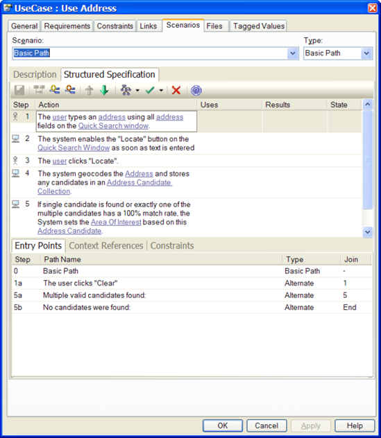
Now you check your alternate and execution paths to ensure none of them are "blank." Each path should have some steps in it. Figure 7-5 shows that each step in the basic path is numbered sequentially. The alternate courses branch from the basic path at a particular step number, then rejoin at a step somewhere in the basic path; e.g., the alternate course "Multiple valid candidates found" branches at Step 5 (so it gets its own step number, 5a), and rejoins the basic path at the end of the same step (Step 5 again).
Another alternate course, "No candidates were found," also branches at Step 5, so it's numbered 5b. It rejoins the basic path at the end of the scenario, so its join point is simply "End" rather than a specific number.
It's possible to make mistakes when converting from a narrative use case to a structured scenario—and sometimes the process helps you to discover errors in the narrative use case.
Two common mistakes are
Alternate paths with no step text
Incorrect "join" information (we cover joins in the next "to-do" item)
EA makes it easy for you to detect these errors by automatically generating an activity diagram that shows the path logic, with branching. Generating an activity diagram verifies the logic of your structured scenario. We'll cover that in Step 6.
Review each alternate and exception path. Write any pre- or post-conditions that you need. Also add any needed joins.
You're preparing the use case for an independent QA team to be able to run tests. Therefore, knowledge that developers have about the use case's pre- and post-conditions can't be assumed to exist in the heads of the QA team. While writing the narrative use case, you would be focusing purely on the narrative and not exhaustively specifying pre- and post-conditions, so as to avoid the dreaded analysis paralysis.
But we've now reached the stage in the process where pre- and post-conditions are important... so it's time to give them some thought.
In order to generate "threads" (paths through the sunny/rainy day scenarios), you need to know where each alternate/exception rejoins the basic path... hence the need for joins. This, again, is detail that can be skipped over when writing the narrative use case, enabling you to get through analysis/design without paralysis.
A good way to check your structured scenario for completeness is to generate an activity diagram. As we just alluded to, a structured scenario is really quite similar to an activity diagram: it has a flow of execution, and it branches and rejoins the main flow at specific points. It's possible to quickly generate an activity diagram from your structured scenario, to get a pictorial overview of your use case's logic flow.
To generate the diagram, click the button in the Scenarios tab that looks like the one circled in Figure 7-6.
Then choose Activity from the list. EA will create the diagram in the Model Explorer as a sub-node beneath the use case. Figure 7-7 shows the activity diagram generated for Use Address (we've reformatted the diagram slightly to fit it on the page).
Tip
Checking your structured scenario with an activity diagram leads to better results in test case generation, as the test scenarios won't generate correctly if the path logic is wrong.

A use case "thread" is an individual acceptance test scenario. Expand your use case "threads" using EA's Create External Tests option.
So, what's a use case thread expander, and why do you need one? Use cases generally have a sunny day scenario (the typical sequence of user actions and system responses) and several rainy day scenarios (eveything else that can happen: errors, exceptions, and less typical usage paths). When you're modeling systems with use cases, you make an up-front investment in "writing the user manual" one scenario at a time, with the expectation of recovering your investment later on in the project. If you do it right, you virtually always recover your investment multiple times over.
One of the places you can leverage the investment you've made in writing use cases is in scenario testing. If you have a use case with one sunny day scenario and three rainy day scenarios, you can expand that use case into at least four "threads," each of which defines a potential scenario test for some part of your system. There's one "thread" for the sunny day scenario and others for some portion of the sunny day combined with each of the rainy day scenarios, in turn. When you've covered all of the permutations, you've got a pretty good start on "black box" acceptance testing your use case from the user perspective.
To generate external tests, click the TestCase Generation toolbar button in the Scenarios tab, as shown in Figure 7-8.
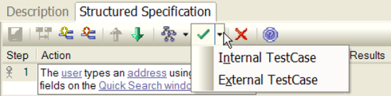
From the two options, choose External TestCase. The Test(s) can be viewed in the 'Scenario' tab of the Testing Window. With the initial release of this capability, you needed to hunt down the generated tests—as we're going to press, (after some intense lobbying by your faithful authors), we've just received word that EA now puts the test case on a diagram much as the ICONIX add-in does, so hunting around isn't necessary anymore. Our thanks to the folks at Sparx for being responsive to our concerns.
Once you've tracked down the Test Case element (in addition to being on an automatically opened test case diagram, it should be in the Project Browser, in the same package as the use case), press Alt+3 to activate the Testing view. Click the element once, and you should see it appear in the Testing view. Do make sure that you're on the Scenario tab in the Testing view (see Figure 7-9), otherwise you won't see a thing.
Note
In Figure 7-9, notice that EA has recognized the domain objects, and shown them as hyperlinks. Linking the domain objects (which is done via Context References in the Scenarios tab) proves useful if you want to generate a robustness diagram from your use case. In fact, you can also link in screens (GUI widgets): if you import the storyboards into the model as screens, and give the screens the same names as used in the use case text, you can contextually link to them. Even cooler, if you generate a robustness diagram, EA creates the boundary classes for you.
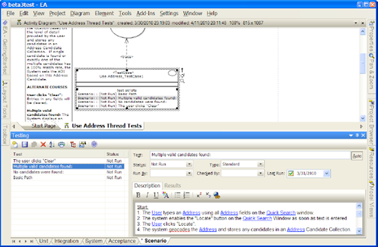
As you may have gathered from the last step, it makes a great deal of sense to put your scenario tests on a test case diagram. Figure 7-10 shows the diagram we created for the Use Address test cases (as an added bonus, EA now performs this little housekeeping task for you automatically). We've added a note on there with the reconstituted "whole use case view" narrative text. Creating a diagram like this will make it easier to find your scenario tests when you return to the model later.

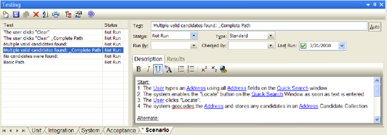
Once you've created the test case and placed it on the test case diagram, with EA's testing view open (just press Alt+3), you can simply click any of the scenarios within it to show the test details (see Figure 7-11). From here you can add additional detail that's useful for generating test plans for your QA department.
Tip
When EA generates the test cases, it also creates some "_Complete Path" scenarios. These can safely be deleted as they're covered already by the other scenarios (we've already deleted them in Figures 7-10 and 7-11).
EA generates the scenario threads automatically, but you'll still need to add information to the test case so that the QA department will know how to exercise the test scenario, and that's done using the EA testing view. Here's an example that actually found a bug in the Mapplet 2.0 project, "Multiple Candidates Found" scenario.
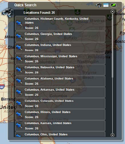
The "multiple candidates" condition can be caused by typing a city name of "Columbus" into the address field, with no state name. Since several states (Georgia, Ohio, etc.) have cities named Columbus, this should result in multiple candidates being displayed in the Address Candidate widget.
We'll talk more about the result of running this test at the end of the chapter.
If you hand a document to your QA team containing a structured, enumerated set of test steps all linked systematically back to the customer's behavioral requirements, we're pretty sure that their eyes will light up in pleasant surprise. Next time they'll probably want to get more involved in the process of creating these tests, which can only be a good thing.
To generate a test plan report from EA, first select a package in the Model Explorer, then go to the Project menu and choose Documentation -> Testing Report. A dialog appears (see Figure 7-12) from which you can then choose which tests to include. (EA can also generate a Test Details report, which, as you'd expect, contains more details.) The generated report is shown in Table 7-1.

Table 7-1. The Work-in-Progress Generated Report for the "Use Address" Scenario Tests
Name | Object | Description |
|---|---|---|
Basic Path | Use Address_TestCase1 | Start:
Result: Basic path complete. Use case ends. |
No candidates were found: | Use Address_TestCase1 | Alternate: When [No candidates were found:] 5b_1. The system displays a message "Location not found" on the Quick Search Window. Result: No candidates were found: complete. Use case ends. |
Multiple valid candidates found: | Use Address_TestCase1 | Alternate: When [Multiple valid candidates found:] 5a_1. The system displays an Address Candidate widget with a list of potential candidates to choose from. 5a_2. The user selects an Address Candidate from the Address Candidate widget. Result: Multiple valid candidates found: complete. Rejoin at 5. |
The user clicks "Clear" | Use Address_TestCase1 | Alternate: When [The user clicks "Clear"] 1a_1. Entries in any fields on the Quick Search Window will be cleared. Result: The user clicks "Clear" complete. Rejoin at 1. |
We thought it would be interesting to share with you how the theory presented in this chapter worked in practice on the Mapplet 2.0 project. As it happened, it was while we were writing this chapter that the first functional version of Mapplet 2.0 became available for testing. Since we had been writing about the Multiple Candidates Found alternate to the Use Address use case (Figure 7-12), Doug—wearing his QA department hat—decided to exercise this capability.
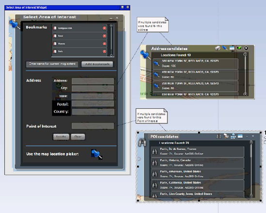
The first "live demo" was conducted over a web session, with the developers at ESRI driving the Mapplet, and Doug watching remotely, requesting demonstrations of various capabilities. Since "Multiple Candidates" was fresh in his mind, he immediately requested that Columbus be typed into the Address/City field, with no state name specified. The developers, having foreknowledge of how the code was built, proceeded to type Columbus into the Point of Interest locator field rather than the Address field (see Figure 7-13). They did this because they knew that the code used two different geocoding services: one that geocoded a "complete" address that required a state name to be specified for a city, and another that did a somewhat looser search that included landmarks and points of interest specified without a complete address. So they knew that typing Columbus with no state name in the Address field would fail, and return "No Matches Found" (see Figure 7-14), and thus they started typing it into the POI locator.
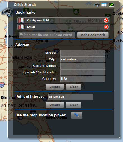
Figure 7-13. The Mapplet search dialog (prototype) where the user can type into either the Address or the Point of Interest fields

Figure 7-14. Caught on camera: the programmers naturally avoided this screen, but a tester walking the user's path (through a defined script based on the use cases) would discover this screen very quickly.
But our "independent QA department" said, "Not so fast. Your Use Address use case says that the locate button is enabled when anything is typed into the address field. It doesn't say anything about a state field being required."
After some discussion, the team resolved that if the first geocoding service returned no results, they could automatically try the second geocoding service. You can see the result in Figure 7-15. This resulted in an improved user experience, since now users can type a city name into the address field as they would expect, and properly get a list of candidate locations.
So what's the moral of the story? We hope you'll agree with the following points:
It's important for someone other than the developers to perform independent acceptance testing.
The acceptance testing activity should exercise all permutations of sunny/rainy day scenarios.
Getting the user experience right (using narrative use cases) is still of paramount importance.
Structured scenarios help us to rigorously test all paths of a use case.
We've tried to give you a step-by-step process in this chapter to put these points into practice.
In this chapter we took a complete narrative use case, structured it into specific scenarios and steps, and generated test cases that can then be handed over to the QA team, and, of course, be walked through with the customer or business analysts to gain their feedback.
Automating scenario tests is an advanced topic and not essential for your project's success, so we cover this in Chapter 11.
Testing use case scenarios, which we covered in this chapter, forms one half of acceptance testing. The other half—testing of business requirements—is covered in the next chapter.