
Chapter 14
Generic Diagrams
A generic diagram is a picture for viewing an underlying model. I use the term generic diagram because it is a starting point for various kinds of diagrams such as data structure diagrams, data flow diagrams, state diagrams, and equipment flow diagrams.
Generic diagrams have a number of features.
- A diagram is a picture with underlying semantics.
- The user clicks through an icon to access semantic content from the background model.
- Lines connect icons and arrowheads indicate the direction of flow.
- Some diagrams restrict connections to discrete locations on icons. Other diagrams permit connections anywhere on an icon.
- An icon can expand into subdiagrams.
- A diagram can be rendered through different notations.
The next section presents some examples and the subsequent four sections explain the generic diagram model by splitting it into four subject areas. The final section then revisits one of the initial examples.
This chapter users an entity type icon (UML—no attribute section, IDEF1X—ellipsis for attributes) for references to entity types that are defined in other subject areas.
14.1 Generic Diagram Examples
Figure 14.1 shows a data flow diagram. The large contour is a high-level diagram that encompasses the internal detail. Figure 14.2 shows an equipment flow diagram for an air conditioning cycle. Figure 14.1 lacks ports and Figure 14.2 has ports (ports are to be explained).


14.2 Diagram Subject Area
A generic diagram is a picture that conveys the meaning of the underlying model. Figure 14.3 and Figure 14.4 support discrete tabs for attaching lines. The gray shading is for entity types that involve metadata.

Diagram subject area, with tabs: UML model. A generic diagram is a picture that suggests the meaning of the underlying model.

An Icon is a picture that is symbolic of something. Examples of Icons include an oval in a data flow diagram and a compressor symbol in an equipment flow diagram. Each Icon has a name, as well as a scale and position that are applied to its corresponding IconType. For example, Figure 14.2 has two Icons for heat exchangers (IconTypes). One Icon is named “Evaporator” and the other Icon is named “Condenser”. Each Icon belongs to a specific Diagram.
A Tab is a discrete position on an Icon for attaching a Line. A Tab has a name, as well as a scale and position that are applied to its corresponding TabType. The relationships between Tab and Line illustrate the Node-Edge directed graph (see Chapter 3). The relationships between Icon, IconType, Tab, and TabType form a homomorphism (see Chapter 5).
A Line is a means for coupling two Tabs. A Diagram is a set of Icons and Lines. Section 14.5 defines DiagramType, IconType, TabType, and LineType.
Figure 14.5 and Figure 14.6 forego Tabs and permit lines to connect anywhere on an Icon.


14.3 Model Subject Area
A semantic diagram has a model that expresses the meaning. Figure 14.7 and Figure 14.8 show the model with discrete ports.

Model subject area, with ports: UML model. A semantic diagram has an underlying model that expresses the meaning.

An Entity is a thing with semantic meaning. Examples of Entities include a data flow in a data flow diagram and a piece of equipment in an equipment flow diagram. An Entity can be represented by an Icon in a generic diagram. An Entity name may or may not be unique within a model.
A Port is a defined place for an Entity, available for a connection. Just as Icons have Tabs, so too Entities have Ports. For example, an expansion valve has inlet and outlet ports. An Entity has many Ports and each Port belongs to a specific Entity.
An Entity may have multiple Ports with the same name. For example, a piping tee has two outputs that are interchangeable (and consequently have the same name). A minimum value function could have up to ten inputs and one output that is the minimum value.
Ports are helpful for some kinds of models and unnecessary for others. If a diagram omits Ports, then connections go directly to Entities.
An EntityType is a classification of Entities. For example, E101 (an Entity) is a heat exchanger (an EntityType). The EntityType specifies the kinds of ports (PortType) that apply.
It would be clumsy to define ports individually. It is better to define them for an EntityType. Thus, an EntityType can have PortTypes. A PortType is a classification of Ports. Each PortType belongs to a specific EntityType. Then each Entity defines Ports corresponding to the PortTypes for its EntityType. Such a mechanism enforces uniformity. Note that the relationships among Entity, EntityType, Port, and PortType form a homomorphism (see Chapter 5).
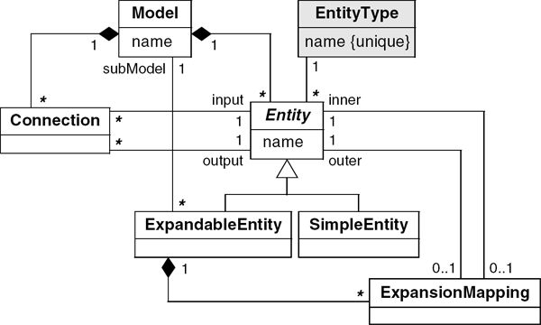
A Model is a set of Entities and Connections and has a meaning that a diagram illustrates. Each Entity and Connection belong to a single Model. Some of the Entities in a Model are ExpandableEntities and lead to submodels. Hence Models can be structured as a hierarchy of arbitrary depth.
There are two kinds of Entities: ExpandableEntities and SimpleEntities. An ExpandableEntity provides a placeholder for a submodel. In an implementation, double clicking the corresponding icon leads to the expansion into a lower-level diagram. As Figure 14.1 illustrates, some Entities can be expanded into submodels with a finer level of detail. A submodel is reusable and can be embedded in multiple places. A SimpleEntity encompasses all other Entities that do not lead to a submodel.
A Connection is a binding between an input Port and an output Port. A Port may, or may not, have a Connection. The various Connections establish the direction of flow through Ports. Port and Connection illustrate the Node-Edge directed graph (see Chapter 3).
The ExpansionMapping takes a Port on an interface (outer Port for an ExpandableEntity) and couples it to a Port (an inner Port) within the corresponding subModel. A Port may participate in one ExpansionMapping as an inner Port, one ExpansionMapping as an outer Port, or in no ExpansionMapping at all. The inner Port must belong to an Entity that is directly contained within the subModel.
Figure 14.9 and Figure 14.10 simplify the Model subject area and permit Connections anywhere on an Entity.

14.4 Model-Diagram Binding Subject Area
Figure 14.11 and Figure 14.12 map diagram constructs to model constructs. Each diagram construct corresponds to one model construct. A model construct can appear in multiple places. These additional relationships lead to three more homomorphisms (considering also the previous subject areas).

Model-diagram binding subject area: UML model. Diagram constructs correspond to model constructs.

14.5 DiagramType Subject Area
Figure 14.13 and Figure 14.14 determine the kind of diagram construct from the DiagramType and kind of model construct. For example, the combination of a DiagramType and an EntityType determine the IconType. Thus North America and Europe may have different DiagramTypes leading to different IconTypes for a heat exchanger.

Diagram type subject area: UML model. The kind of model construct determines the kind of diagram construct.

A DiagramType specifies the kind of notation for a Diagram. For example, IDEF1X and IE are alternative DiagramTypes for a data structure model.
An IconType is the graphical shape for an Icon. The IconType can be determined as follows. An Icon corresponds to an Entity and an Entity has an EntityType. An Icon also belongs to a Diagram of a specific DiagramType. The combination of a DiagramType and an EntityType determines an IconType for the Icon.
A TabType is the graphical shape for a Tab. TabType can be determined in a similar manner to IconType.
A LineType is the graphical representation for a Line that renders a Connection.
14.6 Diagram Example, Revisited
Figure 14.15 shows populated relational database tables for the equipment example at the start of the chapter (Figure 14.2).


14.7 Chapter Summary
This chapter presents a model of generic diagrams. A generic diagram appears as a picture but has semantic content that lies behind the graphics. The model is too large to fit on a single page, so the chapter divides the model into four subject areas. The generic diagram model provides a starting point for various kinds of diagrams such as data structure diagrams, data flow diagrams, state diagrams, and equipment flow diagrams.
I have used the technology in this chapter on several consulting projects.
Bibliographic Notes
This chapter is motivated by my personal experiences with consulting projects. The following notions have been especially useful in practice.
- The uniform mapping of diagram constructs to model constructs.
- The ability to hierarchically nest diagrams and models.
- The ability to display graphical constructs based on the type of diagram.
- The ability to include or omit ports and tabs.