
Introducing Network Scanning
Introduction
About ten years ago I was working as a Network Administrator managing a medium size network. One of my first tasks in this position was to create a network asset database for all network devices. We already had a high-priced, although functionally deficient, network management tool that just wasn’t making the cut. Using the output from the management tool as a starting point I began painstakingly connecting to each network device, and documenting them to inventory the network. This also involved a lot of hours physically traversing buildings, basements, and wiring closets. Finally, it seemed that I had visited every nook and cranny and identified every router, bridge, switch, hub, and archaic telecommunications device retrofitted to the network. For security, I wrote a UNIX script to connect to the known devices and disable physical ports that weren’t being used and enable security features on the devices. This is when things started to get complicated. Suddenly the help desk phones started ringing and people were complaining of lost network connectivity. Alas, there were even more devices out there that we didn’t know about! Luckily the UNIX script was easily reversible. After hearing my woes that evening a “hacker” friend of mine pointed out a new tool for scanning networks that he read about in Phrack magazine. It was a bit controversial, but it was free and it looked like it could do the job. The next day became my first experience with Nmap, a network scanner, and since that day it has been making my life a whole lot easier.
What is Network Scanning?
Network scanning is the process of discovering active hosts on the network and information about the hosts, such as operating system, active ports, services, and applications. Network scanning is comprised of the following four basic techniques:
■ Network Mapping Sending messages to a host that will generate a response if the host is active
■ Port Scanning Sending messages to a specified port to determine if it is active
■ Service and Version Detection Sending specially crafted messages to active ports to generate responses that will indicate the type and version of service running
■ OS Detection Sending specially crafted messages to an active host to generate certain responses that will indicate the type of operating system running on the host
In addition to these basic techniques, advanced network scanners can perform other techniques such as masking the origin of the scanning, enabling timing features for stealthy scans, evading perimeter defenses such as firewalls, and providing reporting options.
The following is an example of the type of output you would expect from a network scan:
■ Host 192.168.100.1 is responding
■ Open ports include:
■ 139/tcp open netbios-ssn
■ 445/tcp open microsoft-ds
■ 3389/tcp open ms-term-serv
■ 8081/tcp open blackice-icecap
■ The operating system is Windows XP SP2
Networking and Protocol Fundamentals
This section provides background information on how networks and protocols work. However, there are many other excellent resources available, including the most popular and undoubtedly one of the best written, Richard Stevens’ “TCP/IP Illustrated, Vol. 1–3.”
Explaining Ethernet
Ethernet is the most popular protocol standard used to enable computers to communicate. A protocol is like speaking a particular language. Ethernet was built around the principle of a shared medium where all computers on the local network segment share the same cable. It is known as a broadcast protocol because it sends that data to all other computers on the same network segment. This information is divided up into manageable chunks called packets, and each packet has a header containing the addresses of both the destination and source computers. Even though this information is sent out to all computers on a segment, only the computer with the matching destination address responds. All of the other computers on the network still see the packet, but if they are not the intended receiver they disregard it.
Ethernet addresses are also known as Media Access Control (MAC) addresses and hardware addresses. Because many computers may share a single Ethernet segment, each one must have an individual identifier hard-coded onto the network interface card (NIC). A MAC address is a 48-bit number, which is also stated as a 12-digit hexadecimal number. This number is broken down into two halves; the first 24 bits identify the vendor of the Ethernet card, and the second 24 bits comprise a serial number assigned by the vendor.
The following steps allow you to view your NIC’s MAC address:
■ Windows 9x/ME Access Start | Run and type winipcfg.exe. The MAC address will be listed as the “Adapter Address.”
■ Windows NT, 2000, XP, and 2003 Access the command line and type ipconfig /all. The MAC address will be listed as the “Physical Address.”
■ Linux and Solaris Type ifconfig –a at the command line. The MAC address will be listed as the “HWaddr” on Linux and as “ether” on Solaris.
■ Macintosh OS X Type ifconfig –a at the Terminal application. The MAC address will be listed as the “Ether” label.
You can also view the MAC addresses of other computers that you have recently communicated with, by typing the command arp –a. The Address Resolution Protocol (ARP) is responsible for mapping IP addresses to MAC addresses.
MAC addresses are unique, and no two computers should have the same one. However, occasionally a manufacturing error may occur that causes more than one NIC to have the same MAC address. Thus, people may choose to change their MAC addresses intentionally, which can be done with a program (e.g., ifconfig) that allows you to fake your MAC address. Faking your MAC address (and other types of addresses) is also known as spoofing. Also, some adapters allow you to use a program to reconfigure the runtime MAC address. And lastly, with the right tools and skill you can physically re-burn the address into the NIC.
Understanding the Open Systems Interconnection Model
The International Standards Organization (ISO) developed the Open Systems Interconnection (OSI) model in the early 1980s to describe how network protocols and components work together. It divides network functions into seven layers, each layer representing a group of related specifications, functions, and activities (see Figure 1.1). Although complicated at first, the terminology is used extensively in networking, systems, and development communities. Understanding what these layers represent and how they work together will facilitate your comprehension of network scanning.
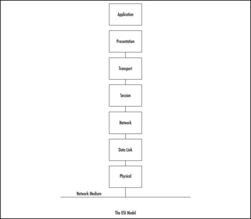
The following sections define the seven layers of the OSI model.
Layer 1: Physical
The first layer of the OSI model is the Physical layer, which specifies the electrical and mechanical requirements for transmitting data bits across the transmission medium (cable or airwaves). It involves sending and receiving the data stream on the carrier, whether that carrier uses electrical (cable), light (fiber optic), radio, infrared, or laser (wireless) signals. The Physical layer specifications include:
■ The timing of voltage changes
■ Data rates
■ Maximum transmission distances
■ The physical connectors to the transmission medium (plug)
■ The topology or physical layout of the network
Many complex issues are addressed at the Physical layer, including digital vs. analog signaling, baseband vs. broadband signaling, whether data is transmitted synchronously or asynchronously, and how signals are divided into channels (multiplexing).
Devices that operate at the Physical layer deal with signaling (e.g., transceivers on the NIC), repeaters, basic hubs, and simple connectors that join segments of cable). The data handled by the Physical layer is in bits of 1 s (ones) and 0 s (zeros), which are represented by pulses of light or voltage changes of electricity, and by the state of those pulses (on generally representing 1 and off generally representing 0).
How these bits are arranged and managed is a function of the Data Link layer (layer 2) of the OSI model.
Layer 2: Data Link
Layer 2 is the Data Link layer, which is responsible for maintaining the data link between two computers, typically called hosts or nodes. It also defines and manages the ordering of bits to and from packets. Frames contain data arranged in an organized manner, which provides an orderly and consistent method of sending data bits across the medium. Without such control, the data would be sent in random sizes or configurations and the data on one end could not be decoded at the other end. The Data Link layer manages the physical addressing and synchronization of the data packets. It is also responsible for flow control and error notification on the Physical layer. Flow control is the process of managing the timing of sending and receiving data so that it doesn’t exceed the capacity of the physical connection or host. Since the Physical layer is only responsible for physically moving the data onto and off of the network medium, the Data Link layer also receives and manages error messaging related to the physical delivery of packets.
Network devices that operate at this layer include layer 2 switches (switching hubs) and bridges. A layer 2 switch decreases network congestion by sending data out only on the port that the destination computer is attached to, instead of sending it out on all ports (hubs). Bridges provide a way to segment a network into two parts and filter traffic, by building tables that define which computers are located on each side of the bridge, based on their MAC addresses. Conversely, bridges also can be used to join separate networks and allow traffic to pass between them.
The Data Link layer is divided into two sublayers: the Logical Link Control (LLC) sublayer and the MAC sublayer.
Layer 3: Network
Moving up the stack, the next layer is the Network layer (layer 3), which is where packets are sequenced and logical addressing is assigned. Logical addresses are nonpermanent, software-assigned addresses that can only be changed by administrators. The IP addresses used by the TCP/IP protocols on the Internet, and the Internet Package Exchange (IPX) addresses used by the IPX/Sequenced Packet Exchange (SPX) protocols on NetWare networks are examples of logical addresses. These protocol stacks are referred to as routable because they include addressing schemes that identify the network or subnet and the particular client on that network or subnet. Other network/transport protocols (e.g., NETBIOS Extended User Interface [NetBEUI]) do not have a sophisticated addressing scheme and thus cannot be routed between different types of networks.
The Network layer is also responsible for creating a virtual circuit (i.e., a logical connection, not a physical connection) between points or nodes. A node is any device that has a MAC address, which typically includes computers, printers, and routers. This layer is also responsible for routing, layer 3 switching, and forwarding packets. Routing refers to forwarding packets from one network or subnet to another. Without routing, computers can only communicate with computers on the same network. Routing is the key to the global Internet, and is one of the most important duties of the Network layer.
Finally, the Network layer provides additional levels of flow control and error control. From this point on, the primary methods of implementing the OSI model architecture involve software rather than hardware.
Devices that operate at the network layer include routers and layer 3 switches.
Layer 4: Transport
Layer 4 is the Transport layer, and is responsible for transporting the data from one node to another. It provides transparent data transfer between nodes, and manages the end-to-end flow control, error detection, and error recovery.
The Transport layer protocols initiate contact between specific ports on different host computers, and set up a virtual circuit. Transmission Control Protocol (TCP) is one such layer 4 protocol. As an example, TCP verifies that the application sending the data is authorized to access the network and that both ends are ready to initiate the data transfer. When this synchronization is complete, the data is sent. As the data is being transmitted, the TCP protocol on each host monitors the data flow and watches for transport errors. If transport errors are detected, TCP provides error recovery.
The functions performed by the Transport layer are very important to network communication. Just as the Data Link layer provides lower-level reliability and connection-oriented or connectionless communications, the Transport layer does the same thing but at a higher level. The two protocols most commonly associated with the Transport layer are TCP, which is connection-oriented, and User Datagram Protocol (UDP), which is connectionless.
The Transport layer also manages the logical addressing of ports. Think of a port as a suite or apartment number within a building that defines exactly where the data should go. Table 1.1 shows the most commonly used Internet ports.
Table 1.1
Commonly Used Internet Ports
| Internet Protocol (IP) Port(s) | Protocol(s) | Description |
| 80 | TCP | Hypertext Transfer Protocol (HTTP), commonly used for Web servers |
| 443 | TCP | HTTP Secure sockets (HTTPS) for secure Web communications. |
| 53 | UDP and TCP | Domain Name Service (DNS) for resolving names to IP addresses |
| 25 | TCP | Simple Mail Transport Protocol (SMTP) for sending e-mail |
| 22 | TCP | Secure Shell (SSH) protocol for encrypting communications |
| 23 | TCP | Telnet, a plaintext administration protocol |
| 20 and 21 | TCP | File Transfer Protocol (FTP) for transferring data between systems |
| 135–139 and 445 | TCP and UDP | Windows file sharing, login, and Remote Procedure Call (RPC) |
| 500 | UDP | Internet Security Association and Key Management Protocol (ISAKMP) key negotiation for Secure Internet Protocol (IPSec) virtual private networks (VPNs) |
| 5060 | UDP | Session Initiation Protocol (SIP) for some Voice over IP (VoIP) uses |
| 123 | UDP | Network Time Protocol (NTP) for network time synchronization |
A computer may have several network applications running at the same time (e.g., a Web browser sending a request to a Web server for a Web page, an e-mail client sending and receiving e-mail, and a file transfer program uploading or downloading information to and from an FTP server). The mechanism for determining which incoming data packets belong to which application is the function of port numbers. The FTP protocol is assigned a particular port, whereas the Web browser and e-mail clients use different protocols (e.g., HTTP and Post Office Protocol (POP3) or Internet Message Access Protocol [IMAP]) that have their own assigned ports; thus the information intended for the Web browser doesn’t go to the e-mail program by mistake. Port numbers are used by TCP and UDP and consist of ports found within a range of 0-65535. Ports 0-1023 are assigned by the Internet Assigned Numbers Authority (IANA) and are considered static. Ports > = 1024 are ephemeral ports, although many are commonly used for specific applications.
Layer 5: Session
After the Transport layer establishes a virtual connection, a communication session is made between two processes on two different computers. The Session layer (layer 5) is responsible for establishing, monitoring, and terminating sessions, using the virtual circuits established by the Transport layer.
The Session layer is also responsible for putting header information into data packets that indicates where a message begins and ends. Once header information is attached to the data packets, the Session layer performs synchronization between the sender’s Session layer and the receiver’s Session layer. The use of ACKs helps coordinate the transfer of data at the Session-layer level.
Another important function of the Session layer is controlling whether the communications within a session are sent as full-duplex or half-duplex messages. Half-duplex communication goes in both directions between the communicating computers, but information can only travel in one direction at a time (e.g., radio communications where you hold down the microphone button to transmit, but cannot hear the person on the other end). With full-duplex communication, information can be sent in both directions at the same time (e.g., a telephone conversation, where both parties can talk and hear one another at the same time).
Whereas the Transport layer establishes a connection between two machines, the Session layer establishes a connection between two processes. An application can run many processes simultaneously to accomplish the work of the application.
After the Transport layer establishes the connection between the two machines, the Session layer sets up the connection between the application process on one computer and the application process on another computer.
Layer 6: Presentation
Data translation is the primary activity of the Presentation layer (layer 6). When data is sent from a sender to a receiver, it is translated at the Presentation layer (i.e., the sender’s application passes data down to the Presentation layer, where it is changed into a common format). When the data is received on the other end, the Presentation layer changes it from the common format back into a format that is useable by the application. Protocol translation (i.e., the conversion of data from one protocol to another so that it can be exchanged between computers using different platforms or OSes) takes place here.
The Presentation layer is also where gateway services operate. Gateways are connection points between networks that use different platforms or applications (e.g., e-mail gateways, Systems Network Architecture (SNA) gateways, and gateways that cross platforms or file systems). Gateways are usually implemented via software such as the Gateway Services for NetWare (GSNW). Software redirectors also operate at this layer.
Data compression takes place in layer 6, which minimizes the number of bits that must be transmitted on the network media to the receiver. Data encryption and decryption take place in the Presentation layer as well.
Layer 7: Application
The Application layer is the point at which the user application program interacts with the network. Don’t confuse the networking model with the application itself. Application processes (e.g., file transfers or e-mail) are initiated within a user application (e.g., an e-mail program). Then the data created by that process is handed to the Application layer of the networking software. Everything that occurs at this level is application-specific (e.g., file sharing, remote printer access, network monitoring and management, remote procedure calls, and all forms of electronic messaging).
Both FTP and Telnet function within the Application layer, as do SMTP, POP, and IMAP, all of which are used for sending or receiving e-mail. Other Application-layer protocols include HTTP, Network News Transfer Protocol (NNTP), and Simple Network Management Protocol (SNMP).
You have to distinguish between the protocols mentioned and the applications that might bear the same names, because there are many different FTP programs made by different software vendors that use FTP to transfer files.
The OSI model is generic, yet provides the appropriate guidelines to be used to explain the majority of network protocols. Various protocol suites are often mapped against the OSI model for this purpose. A solid understanding of the OSI model aids in network analysis, comparison, and troubleshooting. However, it is important to remember that not all protocols map well to the OSI model (e.g., TCP/IP was designed to map to the U.S. Department of Defense (DoD) model). In the 1970s, the DoD developed its four-layer model. The core Internet protocols adhere to this model.
The DoD model is a condensed version of the OSI model. Its four layers are:
■ Application/Process Layer This layer defines protocols that implement user-level applications (e.g., e-mail delivery, remote login, and file transfer.
■ Host-to-host Layer This layer manages the connection, data flow management, and retransmission of lost data.
■ Internet Layer This layer delivers data from the source host to the destination host across a set of physical networks that connect the two machines.
■ Network Access Layer This layer manages the delivery of data over a particular hardware media.
Carrier Sense Multiple Access/Collision Detection (CSMA/CD)
Ethernet uses the CSMA/CD protocol in order for devices to exchange data on the network. The term multiple access refers to the fact that many network devices attached to the same segment have the opportunity to transmit. Each device is given an equal opportunity; no device has priority over another. Carrier sense describes how an Ethernet interface on a network device listens to the cable before transmitting. The network interface ensures that there are no other signals on the cable before it transmits, and listens while transmitting to ensure that no other network device transmits data at the same time. When two network devices transmit at the same time, a collision occurs. Because Ethernet interfaces listen to the media while they are transmitting, they can identify the presence of others through collision detection. If a collision occurs, the transmitting device waits for a small, random amount of time before retransmitting. This function is known as the back off delay. It has also been referred to as a back off timer or exponential back off.
Traditionally, Ethernet operation has been half-duplex, which means that an interface can either transmit or receive data, but not at the same time. If more than one network interface on a segment tries to transmit at the same time, a collision occurs. When a crossover cable is used to connect two devices, or a single device is attached to a switch port, only two interfaces on the segment need to transmit or receive; no collisions occur. This is because the transmit (TX) of device A is connected to the receive (RX) of device B, and the TX of B is connected to the RX of device A. The collision detection method is no longer necessary, therefore, interfaces can be placed in full-duplex mode, which allows network devices to transmit and receive at the same time, thereby increasing performance.
The Major Protocols: IP, TCP, UDP, and ICMP
The next four protocols are at the heart of how the Internet works today.
IP
Internet Protocol (IP) is a connectionless protocol that manages addressing data from one point to another, and fragments large amounts of data into smaller, transmittable packets. The major components of Internet Protocol datagrams are:
■ IP Identification (IPID) Used to uniquely identify IP datagrams and for reassembly of fragmented packets.
■ Protocol Describes the higher-level protocol embedded within the datagram.
■ Time-to-live (TTL) Attempts to keep datagrams and packets from routing in circles. When TTL reaches 0, the datagram is dropped. The TTL allows traceroute to function, identifying each router in a network by sending out datagrams with successively increasing TTLs, and tracking when those TTLs are exceeded.
■ Source IP Address The IP address of the host where the datagram was created.
■ Destination IP Address The destination where the datagram should be sent.
Internet Control Message Protocol
The Internet Control Message Protocol (ICMP) manages errors and provides informational reporting for IP networks. ICMP messages are defined by RFC 792-defined types and codes. The following are common types of ICMP messages:
■ Echo Request (Type 8)/Reply (Type 0) Used by programs such as ping to calculate the delay in reaching another IP address.
■ Destination Unreachable (Type 3): An unreachable message is sent to the source IP address of a packet when a network, host, protocol or port cannot be reached. This can happen when a host or network is down or if there is a network problem. There are a number of subtypes of Destination Unreachable messages that are helpful at diagnosing communication issues.
■ Time Exceeded (Type 11) Occurs when a packet’s TTL reaches 0.
TCP
TCP packets are connection-oriented, and are used most often to transmit data. The connection-oriented nature of TCP packets makes it a poor choice for source IP address spoofing. Several applications use TCP, including the Web (HTTP), e-mail (SMTP), FTP, SSH, Telnet, POP and many others.
The TCP Handshake
An important concept of TCP is handshaking, as depicted in Figure 1.2. Before any data can be exchanged between two hosts, they must agree to communicate. Host A sends a packet to Host B with the synchronize (SYN) flag set. If Host B is willing and able to communicate, it returns the SYN packet and adds an acknowledgement (ACK) flag. Host A indicates to Host B that it received the ACK from B. This is called a TCP 3-way handshake. At this point, data transmission can begin. When the communication between the hosts ends, a packet with the finish (FIN) flag is sent, and a similar acknowledgement process is followed. This process makes up graceful 4-way close as each side of the communication must send a FIN and ACK. If one side of the communication sends a reset (RST) packet during the sequence, the transmission is quickly aborted.

TCP Sequence
Another important component of TCP is sequence identification, where each packet sent is part of a sequence. Through these sequence numbers, TCP handles complex tasks such as retransmission, acknowledgement, and packet ordering.
UDP
UDP packets are the connectionless equivalent to TCP, and are used for many purposes, the most important being that DNS uses UDP for a majority of its name resolution work. DNS has the ability to perform reverse and forward lookups, necessary to determine which IP address corresponds to which hostname and vice versa (e.g., www.example.com is not routable if utilized inside an IP datagram; however, through a DNS system it can find the IP address and include that in the IP datagram to route traffic to). Due to the connectionless nature of UDP, it is considered a speedy protocol and has a wide range of uses, especially for applications that must transmit data very quickly like VoIP, instant messaging, online games, Peer-to-peer (P2P applications, online radio, broadcasts and other streaming media types.
Network Scanning Techniques
Host Discovery
The first part of network scanning is identifying active hosts, known as host discovery. Network scanners perform host discovery by attempting to solicit a response from a host. You can perform host discovery on a single IP address, a range of IP addresses, or a comma-separated list of IP addresses. Some network scanners also allow you to provide an input file that contains a list of IP addresses to scan or an exclude list of IP address not to scan.
Network scanners use a variety of techniques to solicit responses from a target. Host discovery is often performed by the following basic techniques:
■ ICMP ECHO Request An ICMP ECHO request is an ICMP type 8 packet, commonly referred to as a ping. If the target IP address is active, an ICMP ECHO reply (ICMP type 0) is received. Sending ICMP ECHO requests to multiple hosts is known as a ping sweep.
■ ICMP Timestamp An ICMP Type 13 message is a timestamp query. If the target IP address is active it will respond with the current time (ICMP type 14).
■ ICMP Address Mask Request An ICMP Type 17 message is an address mask request. If the target IP address is active it will respond with its netmask (ICMP type 18).
■ TCP Ping A TCP ping sends a TCP SYN or TCP ACK packet to a target IP address. You will need to provide a target port number to send the packet to, such as 21, 25, or 80. If the target IP address is active it will respond, however the type of response depends on the type of packet sent, the target’s operating system, and the presence of firewalls or router access lists.
■ UDP Ping A UDP Ping sends a UDP packet to a specific UDP port at the target IP address. If the target IP address is active, but the UDP port is closed, the system will send an ICMP Port Unreachable. However, due to the connectionless nature of UDP, this type of UDP ping is unique in that no response from the target also indicates the possibility that the port (and therefore, the host) is active.
These host discovery methods are not fool proof. While no response could give an indication of the target’s active status, it could also mean that a router or firewall is dropping the packets. Also, some operating systems may not comply with the requests and drop the packet.
Port and Service Scanning
Once you have identified an active host you can attempt to identify the ports and services running on that host by performing port scanning. When an attacker performs port scanning, it is often compared to a burglar checking for unlocked doors and windows on a house. Knowing the open ports and services helps attackers further investigate vulnerabilities that can be possible entry points into the system. Port scanning sends a request to solicit a reply from ports on a target computer. There are many different types of port scanning techniques. Most of them can be loosely categorized as the following:
■ Connect scan. Connect scans perform a full TCP three way handshake and open a connection to the target. These scans are easily detected and often logged by the host. If a TCP port is listening and not firewalled it will respond with a SYN/ACK packet, otherwise the host responds with a RST/ACK packet.
■ Half-open scan. A half open scan does not complete the full TCP three way handshake. It is also referred to as a SYN scan. With a half open scan, when the scanner receives a SYN/ACK from the target host, implying an open port on the target, the scanner immediately tears down the connection with a RST. This type of scan used to be considered a stealth scan because the connection was not completed and therefore not logged by the host; however it is easily detected by intrusion detection systems.
■ Stealth scan. Stealth scans use various flag settings, fragmentation, and other types of evasion techniques to go undetected. Some examples are a SYN/ ACK scan, a FIN scan, an ACK scan, a NULL scan, and a XMAS (Christmas Tree) scan. Each of these scan types are covered in detail later in the book.
Port scanning solicits a variety of responses by setting different TCP flags or sending UDP packets with various parameters. Both TCP and UDP each have 65,536 possible ports (0 through 65,535). You may scan all of them or a subset, such as the most commonly used ports. For example, it is routine to scan the well-known ports below 1024 that are associated with common services such as FTP, SSH, Telnet, SMTP, DNS, and HTTP. Once a port is discovered, a network scanner may perform additional examination to determine the actual version of the service running on the open port. As with host discovery, port scanning is also subject to intervention by routers and firewalls, thus port responses may be dropped. Also, some operating systems may not comply with the requests and drop the packet.
OS Detection
Operating system detection, also called fingerprinting, is used to determine the type of operating system that is running on the target. Fingerprinting can be performed both actively and passively. With active fingerprinting the network scanner sends several packets to the target with various settings. The responses to the settings are analyzed and compared to a list of known request/response values to find a match. Operating systems are all built with identifying characteristics within their TCP/IP stacks and configurations. This includes settings such as the TCP window size and TCP initial sequence numbers. Passive fingerprinting also looks at deviations in TCP/IP stack implementations; however it looks for these deviations by analyzing the traffic on the network. Passive fingerprinting does not send any packets to the target; it passively monitors the target’s communications.
Optimization
There are several performance optimization techniques for network scanning; however they are dependant on the features of the scanner. High performance network scanners will perform many functions in parallel and utilize efficiency algorithms. For example, a common technique is the ability to scan many targets in parallel. Some scanners allow you to modify timing parameters such as timeouts. Decreasing the time that the scanner waits for a response or the time between retries may increase performance. Another optimization technique is to narrow the number of targets and number of ports to scan. For example, instead of scanning the entire network at once, scan each network segment separately or scan for a particular port or service type.
Evasion and Spoofing
A secure network blocks scanning techniques and alerts when a scan is detected. Firewalls block scanning attempts or drop responses to request packets. Intrusion detection systems (IDS) monitor network and host activity and create alerts when traffic matches predefined signatures. Most scanning techniques are easy to detect and will easily trigger IDS alarms. Attackers therefore use a variety of techniques to scan in stealth mode to evade firewalls and IDSs, including the following:
■ Low and slow scanning Security applications and IDSs watch for a large number of connections during a short period of time to hosts and ports. Low and slow scanning is a painfully slow technique that limits the number of hosts and ports that are scanned in a specified time period. Scanning over a long period of time reduces the chance of triggering an alert. If the attacker is patient, this type of scan can be very successful simply because it has a higher chance of not being detected.
■ Fragmentation Fragmentation splits up TCP-based scan requests over several packets in an attempt to evade detection.
■ Spoofing and decoys Attackers often spoof their IP addresses and use decoys to evade detection. Spoofing changes the source IP address of the scanner. This technique isn’t effective for obtaining scan results since the scanner won’t receive replies; it won’t be able to obtain any information about the targets. Decoys are fake hosts that appear to be scanning your network at the same time the real attacker is also scanning. This makes it difficult to determine which IP address is the valid scanner.
■ Source ports Another firewall evasion technique is to specify a source port that is allowed through a firewall such as port 53 (DNS).
■ IP options Some scanners also allow you to modify IP protocol options to evade firewalls and specify a route to the target.
■ Advanced techniques Other advanced evasion techniques include FTP bounce scans, idle scans, or proxy tunneling. These will be covered in more detail later in this book.
Common Network Scanning Tools
There are numerous network scanners available including free, open source and commercial products. The following list contains a few of the more popular scanners:
■ Nmap Nmap is a free open source network scanning utility. It runs on most operating systems including Linux, Windows, and MacOSX. Nmap is the most widely used network scanner and there are many third party tools that integrate with Nmap. It can be downloaded from http://insecure.org.
■ Superscan Superscan is a free Windows-based network scanner developed by Foundstone. It can be downloaded from www.foundstone.com/us/resources-free-tools.asp.
■ YAPS Yet Another Port Scanner (YAPS) is a free Windows-based port scanner. It has a simple graphical interface and can scan many targets simultaneously. It can be downloaded from www.steelbytes.com.
■ Angry IP Scanner Angry IP Scanner is a small, fast IP and port scanner. It runs on Windows, Linux, and Mac OSX. It can be downloaded for free from www.angryziber.com/ipscan/.
■ NEWT NEWT is both a freeware and commercial Windows-based network scanner. The freeware version has not been updated since 2003, but the commercial version is updated frequently. It is available at www.komodolabs.com.
Who Uses Network Scanning?
System administrators, network engineers, auditors, and security engineers all use network scanners for various reasons including the following:
■ Compliance testing
■ Asset management
■ Network and system inventory
For example, OS and version scanning is used to manage patches, upgrades and to monitor device and service uptime. Port scanning is used to identify services on a host for policy compliance. Network scanning is also used to verify the firewall filter operation.
Network scanning is a double-edged sword. While network, system, and security professionals use it for assessing and managing systems and networks, intruders use network scanning for harmful purposes. A network scanner is a tool, and like all tools, it can be used for both good and bad purposes. Once an intruder has a profile of the organization from performing reconnaissance or footprinting, he or she uses network scanning to gather specific information about the target systems. The intruder scans the target network and systems to identify active hosts, operating systems, and available services and applications. The attacker then uses this information to exploit potential vulnerabilities.
Detecting and Protecting
Because attackers also use network scanning, you must detect when your organization is a target and protect against network scanning activity. Monitoring for port scans can be a tricky task. You must find the right balance between performance and security. For example, it would not be effective to monitor for SYN scanning by alerting on every SYN packet. Most products perform scan detection by monitoring connection attempts to a large number of hosts or ports from a single source IP over a period of time. To keep false alarms at a minimum it is recommended to set realistic thresholds for alerting. For example, you could set a threshold for 25 SYN packets sent to closed ports within a 5 second interval. Keep in mind this is an example figure, the acceptable number of packets received in a given time period will depend on your own specific environment. You could implement filters to detect a variety of scan attempts such as monitoring for a large number of ACK or FIN packets, or packets with strange combinations of TCP flags. These types of rules should also be tested in your infrastructure for efficiency and to minimize pesky false positives or negatives.
One of the easiest methods of protecting against network scanning is to block ping sweeps by not allowing ICMP ECHO requests to enter your network. This can be performed with a router access control list or with a firewall rule. However, remember there are many non-ICMP ECHO techniques used to scan a network. You can also implement a firewall or inline intrusion prevention system (IPS) that monitors connection state. It will block or alert on connection attempts to enter a network with flags such as ACK or FIN, that are not part of a pre-existing connection. Performing your own network scans from outside the network is a great way to protect your network and systems by determining what the attackers can see. Then you can close ports and implement firewall rules as necessary.
There are also open source port scan detection tools available. One such tool is the Linux-based Port Scan Attack Detector (PSAD), nicely maintained by Cipherdyne and available here: www.cipherdyne.org/psad/.
Network Scanning and Policy
There is one very important topic that we would like to take time to address. Before running your newly installed network scanner at work, please read your company policy! A properly written and comprehensive “Appropriate Use” network policy will more than likely prohibit you from running network scanners. Usually the only exception to this is if network scanning is in your job description. Also, just because you may provide security consulting services for company clients, this does not mean that you can use your scanner on the company network. However, if you are an administrator and are allowed to legitimately run a network scanner, you can use it to manage your network, perform security audits, enforce the company’s security policy, and much more. If the policy on the use of network scanners is not clear in your organization, take the time to get permission in writing from the appropriate departments before using a network scanner or any other security-related tools.
Also, if you provide security services for clients, such as an ethical hacker who performs penetration testing, be sure that the use of network scanning is included in your Rules of Engagement. Be very specific about how, where, and when it will be used.
Another word of caution: many ISPs prohibit the use of network scanning in their “Appropriate Use” policy. If they discover that you are scanning devices attached to their network, they may disconnect your service. The best place to experiment with network scanning is on your own home network that is not connected to the Internet. Most network scanners will let you scan your local system. If you get bored with local scanning you can use two computers with a crossover cable between them, or a virtual machine application. You can configure one as a client, and install server services on the other, such as Telnet, FTP, Web, and mail. Install the network scanner on one or both computers and have fun!
Summary
Network scanning is a key component to maintaining secure networks and systems. Proactive management can help find issues before they turn into serious problems and cause network downtime or compromise of confidential data. In addition to managing network and system security, your network scanner may be used for a number of network and system administration tasks.
This chapter provided an overview of network scanning and the specific techniques used to scan networks and systems. To do this adequately it was also necessary to provide some background information on how TCP/IP works. A good networking and protocol reference should be on every administrator’s bookshelf. We provided a list of network scanning tools and some potential uses of network scanning by both the good guys and bad guys. While network scanning is a beneficial tool for a system, network, or security administrator, attackers may also use it against us. Thus, we provided an overview of ways to detect and protect against network scanners.
Now that you have been introduced to network scanning and the techniques used to discover active hosts, ports, services, and operating systems you are armed with the knowledge to start exploring a network scanning product. This book covers the Nmap network scanner and its plethora of uses and add-ons. It was touched on in this chapter, but as you read through this book you will continue to discover the variety of ways to use Nmap in the enterprise environment.
Finally, remember to only use network scanning if you have permission and the law is on your side. A curious, up-and-coming administrator could easily be mistaken for an intruder. Make sure you have permission, or use your own private network to experiment.
Solutions Fast Track
What is Network Scanning?
☑ Network scanning discovers active hosts on the network and information about the hosts, such as type of operating system, active ports, services, and applications.
☑ Network scanning often uses network mapping, port scanning, service and version detection, and operating system detection.
☑ Advanced network scanners include scanning optimization and stealthy scanning techniques.
Networking and Protocol Fundamentals
☑ Ethernet is a shared medium that uses MAC or hardware addresses.
☑ The OSI model has seven layers and represents a standard for network communication.
☑ The IP protocol contains the source and destination IP addresses used for network scanning.
☑ TCP performs a three way handshake to make a connection between two devices.
☑ Both TCP and UDP use ports to communicate.
Network Scanning Techniques
☑ Host discovery identifies active hosts on the network.
☑ Host discovery often uses ICMP ECHO requests to solicit a reply from a host, but non-ICMP methods may also be used.
☑ Firewalls and border routers may block host discovery attempts.
☑ Port scanning identifies open ports and services by attempting to solicit a reply from a specific port on a device.
☑ Port scanning uses a variety of TCP flags or UDP parameters to solicit replies from hosts and to attempt to evade firewalls and border routers.
☑ Active fingerprinting sends several packets to a device with a variety of parameters in order to evaluate the replies and determine the operating system against a known list of requests and replies by OS.
☑ Parallelism and timing parameters provide performance optimization for network scanners.
☑ Low and slow scanning, fragmentation, and spoofing are methods used by advanced network scanners to evade detection by firewalls and intrusion detection systems.
Common Network Scanning Tools
☑ Nmap is the most popular and widely used free network scanner.
☑ Superscan is a popular free Windows-based network scanner.
☑ NEWT is a popular network scanner available for free or as a commercial product.
Who Uses Network Scanning?
☑ Network, system, and security professionals use network scanning for a variety of administrative functions such as security auditing, compliance testing, asset management, and network and system inventory.
☑ Network scanning may be used to manage patching and upgrades, monitor system uptime, assess policy compliance, verify firewall filter operation, and discover unauthorized devices and applications.
☑ Attackers use network scanning to identify active hosts, open ports and services on a target device. The attacker may then exploit discovered vulnerabilities.
Detecting and Protecting
☑ Most products perform scan detection by monitoring connection attempts to a large number of hosts or ports from a single source IP over a specific period of time.
☑ Refining thresholds for your specific infrastructure reduces false positives.
☑ Protect your network from ping sweeps by not allowing ICMP ECHO requests to enter your network.
☑ Products that monitor connection state will detect packets that are not part of an existing connection.
☑ Regularly perform your own network scan attempts from outside of the network, (if you have permission) to see what attackers can see.
Network Scanning and Policy
☑ A good Appropriate Use policy will prohibit the use of network scanners by anyone not specifically designated to perform this function.
☑ Make sure you have permission to use a network scanner on a network that is not your own.
☑ Read the appropriate use policies of your ISP before using a network scanner.
Frequently Asked Questions
Q: Our security administrator uses a network scanner all the time to look for open ports and potential security issues, but as a network and system administrator I never thought about using it. How do I make sure that I am allowed to use a network scanner as part of my job?
A: First, locate the individual that is responsible for the overall security of the organization. This may be the Chief Security Officer (CSO) or Director of IT, or someone else. This is likely the same person that is responsible for the Appropriate Use policies. Next, meet with this person and explain how and why you intend to use a network scanner. Make sure you get signed permission in writing so that you can proceed with these activities.
Q: I keep seeing messages in my logs about port scanning activity, how do I know if this is something legitimate or an attacker?
A: First, report the activity to the security department or team. If they are unaware of this activity they will most likely use a network sniffer, such as Wireshark or tcpdump, to start tracing the source of the scanning.
Q: I see scanning attempts daily on the outside of my border router, should I be concerned?
A: Unfortunately scanning is a typical activity on the Internet. It may be script kiddies, worm traffic, spammers, or other intruders. If you run an IDS outside of your network at the border router you will see a lot of this activity. Make sure your border router and firewall are blocking the scans from reaching inside the network. Also make sure you are using an IDS on the internal network to identify attacks that may result from an attacker or worm successfully scanning, identifying, and exploiting a vulnerability on your network or systems.
Q: Can I trust the results of my network scanner 100%?
A: No. The biggest problem is that routers and firewalls may block responses to a scanner. Thus, the scanner may report that certain systems are inactive, when they are actually active, or that certain ports are closed when they are actually open. Another reason not to fully trust a network scanner is the availability of tools to trick the scanner. For example, there are tools, discussed later in this book that can send fake responses to OS detection. So a system may be a Linux system that is reporting as a Windows system. This doesn’t mean that you shouldn’t run a network scanner, or trust it at all. It just means that you keep this in mind as you perform scanning and analyze the results.