
The previous chapter showed that the BeagleBone Black board is designed to accept hardware add-ons called capes and how they ease the setup of projects. We can apply the same philosophy to the software part, thanks to the different tools that help developers. Now, in this chapter, we will go further with our hands-on approach by creating our applications.
You'll then have an overall view of how you can realize your own ideas without many difficulties. Thus the main purpose of this chapter could be resumed as:
Give a man a fish and you feed him for a day; teach a man to fish and you feed him for a lifetime
I hope that you'll be more eager to develop projects by yourself afterwards.
In this chapter, we will cover the following topics:
- Presenting the "matrix revolution"
- Diving into the software parts
- Example 1 – our first client server application
- Example 2 – improving the first example by adding functionalities
- Example 3 – creating animated graphical patterns
- Final words
This project aims to connect a matrix to the BeagleBone board so that it can be remotely accessed through a network connection. For this purpose, you will program the following parts:
- The client that will establish a connection to the server
- The server on the BeagleBone where you'll be able to interact with all the connected devices

This project allows you to approach the following technologies:
- BeagleBone/I2C: This board communicates with the matrix using the I2C protocol (introduced later).
- Adafruit matrix: The matrix itself in the bicolor version. The good part is that when you buy two colors, you can have three (the combination of green with red will give you the orange color too).
- Client: Even though the hardware part will be the same among the different examples, you are going to implement different ways to control the matrix. These examples will then be different versions of a client program, which can run on a single PC, for example.
- Server: From the other side of the network, the BeagleBone board will have a dedicated program that will wait for commands to be executed. Similar to the client, this part will also evolve along with the project.
- Python: This is a well-known and widely-used language that lets you focus on the project quickly.
- Code repository: Writing code is an activity that lives, which moves as programs are not written in stone. This is why a companion repository for this book has been created on GitHub. With this online code base, you only need to retrieve the Matrix Revolution repository with the local
gitcommand. As you have already used Git in the previous chapters, you know that with a simple command you are sure to work with the last changes (corrections, improvements, fixes, and so on) from the author. The dedicated site can be found at http://dlewin.github.io/BeagleboneBlack-Server-Book, as shown in the following screenshot: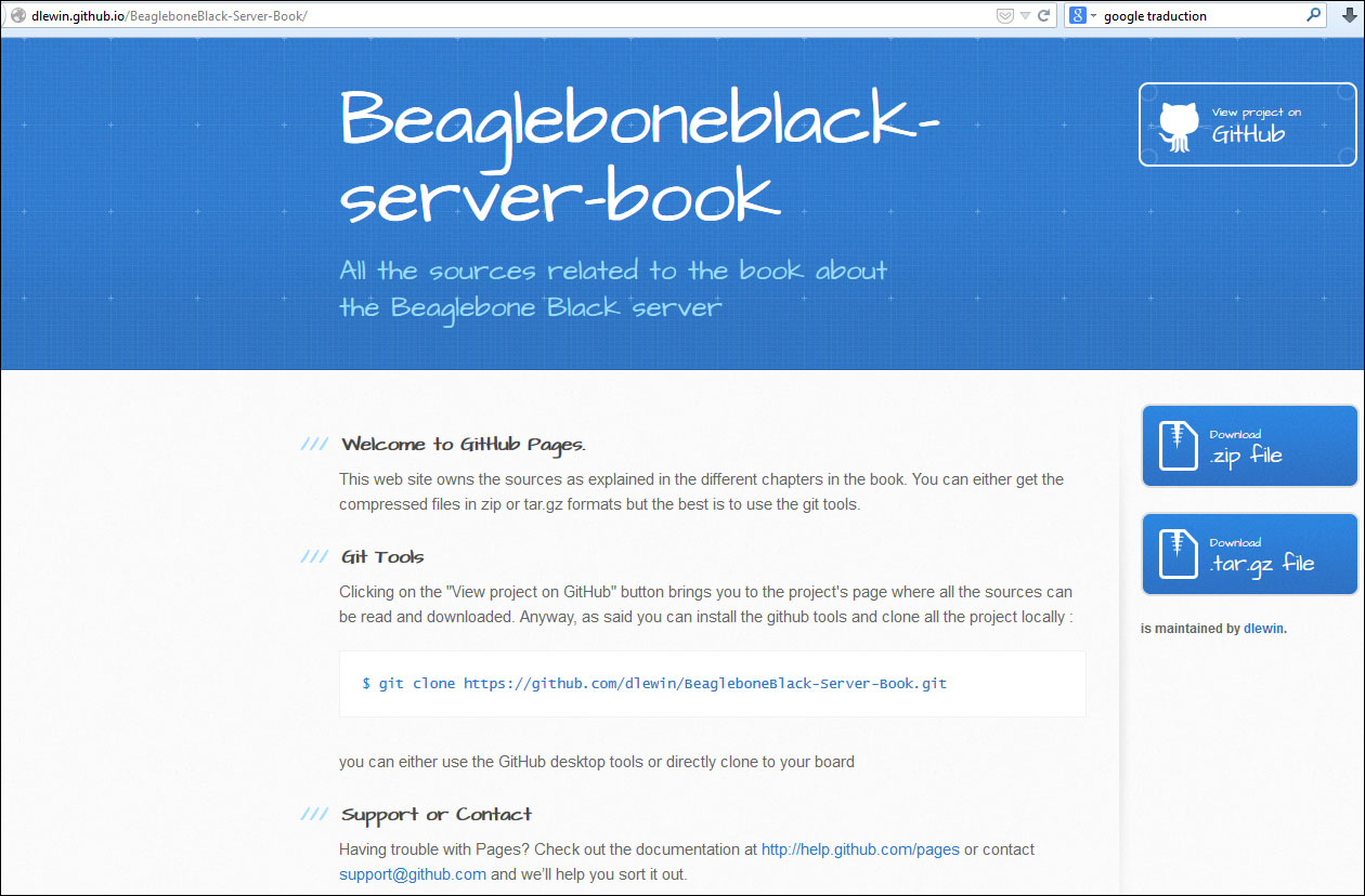
- This is the entry point, in the form of a website where you can grab the latest version of the projects as a compressed file and get basic details.
- Accustomed coders will prefer a more detailed view with commit dates, information about which files have been pulled in the repository, and so on. Indeed, this other view of the site will let you walk through, read, or retrieve the code in many different ways.

- This being said, the best (and the only) way to get the code is to use
gitfrom the command line of your board:git clone https://github.com/dlewin/BeagleboneBlack-Server-Book.git
Now that you know what you are going to play with, we'll mix these technologies in three flavors, elaborating in a progressive manner. Obviously, this implies that you need some additional knowledge but rest assured that it will be explained sufficiently. Having said that, you need to be at ease with the example and its concepts before you go to the next step.
The graphical representation of this project will be a matrix of LEDs that Adafruit has arranged in a very handy product, and there is no need to for additional components such as resistors, power circuits, and so on: the box contains all that is required to start quickly.
You can get more details from their website at http://www.adafruit.com/products/902.
When you receive it, you just need to solder some pins as indicated in the Adafruit documentation and it's ready to be used. As shown in the presentation, the messages between the matrix and the BeagleBone Black board use a form of the I2C protocol. Let's look how it works.
Whichever board you use in your projects—Arduino, Raspberry, Mini2440—most of the time, you need to deal with sensors, components, or devices that "talk" I2C or SPI. These data buses simplify our coder's life. Indeed, our matrix just need to be managed with only two signals, SCL and DAT, to execute all the operations.
Instead of a wire for each function, a communication is specified by Philips on the two wires with the protocol part of the I2C. Fortunately, this happens behind the scenes, thanks to the I2C Linux driver.
Tip
Are you interested in getting more details about the I2C bus? Check out http://support.saleae.com/hc/en-us/articles/200730905-Learn-I2C-Inter-Integrated-Circuit for an interesting explanation.
Using the driver means that, even though you use the I2C protocol, you never have to deal with the bus message frames, CRC, and all the detail of the protocol, so you can focus on the data to be sent from BeagleBone to the matrix.
After this short introduction to the I2C protocol, we can now set up the connection between the two devices, as shown here:

Note
This image is not a drawing. You can obtain the source file from the GitHub website as a design file in order to use it with Fritzing (http://fritzing.org/home/), an open source electronic design software.
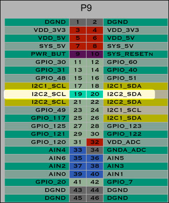
Assuming that the matrix is now built, we can wire the matrix according to the following schema:
- SCL: Pin 20
- DAT: Pin 19
- +5V: Pin 6
- GND: Pin 2
The synoptic is easy to understand: just wire the four pins to the board. However after this, if you want to access the complete header's reference, check the header documentation provided by the BeagleBone Wiki at http://elinux.org/Beagleboard:Cape_Expansion_Headers.
For our experiments, we use the I2C-2 because the device's tree file defines that the I2C-1 is already used.
Usually, you should ensure that the function pin you intend to use is free.
Note
This subject is outside the scope of this book and requires you to understand the device tree mechanism. A complete explanation can be found in the Free Electron presentation at http://free-electrons.com/pub/conferences/2013/elce/petazzoni-device-tree-dummies/petazzoni-device-tree-dummies.pdf.
As BeagleBone Black was the first to follow the recommended guidelines, our board is used as an example along with the explanation, which is handy.