CHAPTER 6
Short-Circuit Analysis—1 (Symmetrical Fault Analysis
6.1 Introduction
Power system equipments are required to work under unpredictable conditions, such as with a live conductor touching the ground (the short circuit problem) or a lightning striking the conductors (the over voltage problem). Under faulty conditions of the system healthy phase voltages may rise beyond the rated value, the faulty phase current may increase abnormally or both these anomalies may occur concurrently. These are undesirable effects that may lead to damage of costly equipment due to the break down of insulation. A short circuit occurs when two points at different potentials are connected either with zero resistance (a dead short circuit) or with a substance of low resistance (a simple short circuit). A short circuit current is several times higher than the rated current of the equipment. In a short circuit, heavy current flows through all parts of the system into the defective area or fault. This problem is of particular significance in the present-day inter-connected power systems. A fault may be designated either as a series or a shunt fault. While a series fault is due to the breakage of conductors, a shunt fault arises due to short circuit. Shunt faults are more serious than series faults, and many times series faults are converted to shunt faults. The excess MVA at the location of a fault is referred to as the fault level at that point.
6.1.1 Applications of Short Circuit Study
Calculation of short circuit currents gains importance in the design of protective switch gear like isolators, circuit breakers, short circuit current limiting reactors and the design of settings for protective relays.
Faults are divided into two types:
- Symmetrical or balanced faults
- Unsymmetrical or unbalanced faults
Balanced faults occur infrequently, but they are serious due to heavy fault levels. During these faulty conditions, symmetry (or balanced condition) may be observed in all the three-phases. The only fault that comes under this category is the three-phase fault. Knowledge of the three-phase fault MVA is essential to estimate the breaking capacity of the circuit breaker, as these fault levels are the highest. Fault levels are maximum when all the three-phases are involved in a fault. Due to symmetry, knowledge of the condition of one phase in a three-phase system is sufficient to estimate the condition of other phases. This simplifies short circuit calculations to a great extent as calculations are made on a single-phase, rather than on a 3-phase basis.
Unbalanced faults occur frequently, and involve one or two phases only. Symmetry condition in the system is lost due to these faults, making fault calculations more difficult than in the case of three-phase faults. Unsymmetrical fault analysis is discussed in the Chapter 7.
6.2 Power System Representation
A power system is made up of three components, namely, generators, transformers and transmission lines. Consider a simple power system network comprising these three components and shown as a single line diagram as in Figure 6.1.

Fig 6.1 Single Line Diagram Representation of a Simple 3-Bus Power System Network
6.2.1 Description of the Single Line Diagram Representation
The single-line diagram of a power system represents a three-phase power system which works perfectly under balanced condition. A three-phase system consists of four lines, namely, R-phase, Y-phase, B-phase and Neutral. Let us understand how these four lines can be represented to a single line.
No consideration of Neutral Line:
Under balanced conditions,
Neutral line current In = IR + IY + IB = 0 and
Neutral line voltage Vn = In Zn = 0 where Zn is the neutral line impedance.
Neutral line power Sn = Vn In = 0. The power carried by the neutral line is zero, as both voltage and current are zeros. For this reason, the neutral of a balanced three-phase system is referred to as a Zero Power Bus (ZPB). The neutral line is insignificant as there is no current, voltage or power. This reduces system from four lines to three lines.
Consideration of only one phase
In addition, as the system is working under balanced conditions, the knowledge of current, voltage or power in one phase is enough to estimate these quantities for the other phases. In other words, calculations on a single-phase basis are enough to claim for three-phase analysis. This reduces the three lines to a single line (or single-phase).
6.2.2 Assumptions made in Fault Calculations
Manufacturers design circuit breakers with standard ratings such as 500, 750 and 1000 MVA. Accurate fault MVA calculation is not required as the circuit breaker is not designed to calculated value. Instead, a nearest high MVA-rated circuit breaker is to be chosen for placement at the fault location. Further, since the reactance of individual equipment is much higher than the resistance, the resistance can be neglected. In view of the above discussion, the following assumptions are made for the simplification of symmetrical fault analysis.
- The generator is represented as a constant voltage source 1<0 per unit behind the sub- transient, transient or steady-state reactance, depending upon the fault current required in sub-transient, transient or steady-state periods.
- The saliency effect of a generator is neglected. Hence cylindrical or salient pole machines are treated the same.
- All generators are represented by a single voltage source 1<0 p. u as all emfs are equal and in phase.
- Compared to the short circuit current, the no load current of a transformer is negligibly small and hence shunt branches of the transformer are neglected.
- Shunt capacitance of transmission lines is neglected.
6.2.3 Network Modeling
Now, the power system represented as a single line diagram is converted to an equivalent reactance diagram as shown in Figure 6.2.

Fig 6.2 Reactance Diagram of the Power System Shown in Figure 6.1
In the figure, the generator is represented by a constant voltage source behind the reactance; the transformer is shown as a series reactance element (provided per unit reactance is used); and the transmission line is represented by a series reactance element. The ‘per unit method', which uses per unit values of electrical quantities simplifies power system calculations. It is customary to use this method for performing fault calculations and knowledge of arriving at per unit values is essential.
6.3 Per Unit Method
A per unit value has no unit. A quantity expressed in a certain unit becomes unit less when it is divided by another quantity expressed in the same unit. Hence, per unit value is defined as:
The base or reference value is chosen by us according to our convenience.
Example 6.1
Let the actual current be 100 amps. Determine p. u. current if the
- base current is chosen as 10 amps
- base current is chosen as 20 amps
Solution:
Example 6.2
Let the actual rating of the equipment be 100MVA. Determine p. u. MVA for the chosen base MVA: a) 200 MVA and b) 100 MVA.
Solution:
- if base MVA is chosen as 2000, then p. u MVA = 0.5 p. u
- if base MVA is chosen as 100, then p. u MVA = 1 p. u
6.3.1 Selection of Base Values
It is important to select appropriate base values for converting the actual rating of electrical equipment to per unit values. Once the base values are chosen, converting actual values to per unit values becomes a simple task. In this context, we may ask the question: Is it required to select base values for all electrical quantities?
The answer is Yes as well as No.
The answer is Yes if we come across different electrical quantities in a problem. To convert it into per unit value, base value is needed. Hence we need to select base values for all electrical quantities.
The answer is No in fault calculations, where this method is normally used. We come across only four electrical quantities in these calculations:
- Rated power in MVA,
- Rated voltage in KV,
- Rated current in amperes and
- Impedance or reactance in Ohms.
Hence, it is sufficient to choose base values for these quantities, as other quantities are absent in the calculations. However, base values are not selected for all the four quantities. These values are set for power and voltage, and those for current and impedance are derived from them. All the four quantities are treated as a set of base values.
6.3.2 Base Quantities
Let Base power = MVAb or KVAb and Base voltage = KVb.
Now, Base current Ib in amperes is:
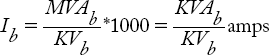
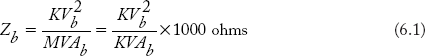
The Base impedance Zb in Ohms is:
Note:
- The dimension of the four base quantities are chosen to suit the given power system
- Percentage value of the quantity is:

- When the base values are changed from old to new, the p. u values changes. Accordingly, the formula for new p. u. impedance is:

Example 6.3
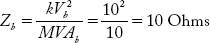
A 10MVA, 10 KV equipment has an impedance of 1Ohm. Find its
a) p. u impedance
b) % impedance
Solution:
Take the rating of the equipment as its base value:
- Base impedance
Therefore,

- % impedance = p. u impedance × 100
0.1 × 100 = 10%
Example 6.4
For the equipment in Example 6.3, the base values are chosen as 20MVA, 5KV. Find the new % impedance.
Solution:
Old base values = 10MVA, 10KV
New base values = 20MVA, 5KV
Using Equation (6.3)

6.3.3 Advantages of the Per Unit Method
The following are the advantages of the per unit method.
- It simplifies power system calculations.
Power system quantities are big numerical values. For example, power is expressed in KVA or MVA and voltage in KV. The per unit method enables such big quantities to be expressed in small numerical values. This makes power system calculations simple and easy. - It avoids the discontinuity problem posed by the presence of a transformer in the power system network.
Consider the power system shown in Figure 6.2. In the figure, the transformer is shown as a series reactance element. This is not possible when the actual ohm values are considered because of the difference in equivalent impedance of the transformer (in Ohms) when referred to the HV side and the LV side. Further, the transformer divides the network into two sides — the high voltage, low current side and the low voltage, high current side. No electrical quantity (except the power) is the same on either side of the transformer, and this leads to a problem in representing it in an equivalent network. In other words, the transformer poses a problem of discontinuity in the representation of power system network. The solution to this difficulty is to represent the transformer as per unit equivalent impedance, which is the same on both HV and LV sides. If impedance value is the same on both sides of transformer, then it can be represented as a series reactance element and discontinuity can thus be avoided.
To make equivalent impedance of the transformer same on either side, individual sets of base values must be chosen for the HV and LV regions based on the following directions:
- A common base power is chosen for the LV and HV sides of the transformer. This may be the rating of the transformer itself or the largest MVA rating of any other equipment in the network.
- Two different base voltages are chosen for both sides in such a way that their ratio is exactly equal to the transformation ratio of the transformer.
The following numerical example illustrates the selection of base values in the networks containing transformers.
Example 6.5
Choosing the transformer ratings as base values, prove that the equivalent impedance of a transformer in p. u referred to the LV and HV sides is the same.
Solution:
Base power on the LV side = Base power in HV side = MVA rating of transformer = MVAb
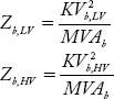
Base voltage on the LV side = KV rating on LV side = KVb,LV
Base voltage on the HV side = KV rating on the HV side = KVb,HV
As the rated voltages of the transformer are taken as base voltages, their ratio is exactly equal to the transformation ratio of the transformer. Now the base impedances on the LV and HV sides are:
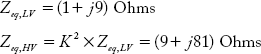
Let the equivalent impedance of the transformer referred to the LV side be Zeq,LV Ohms.
The p. u value is

We know,

In the above step, the numerator Zeq,HV = N2 × Zeq,LV
and the denominator is Zb,HV.
![]()
Hence, the condition is proved.
Example 6.6
A single-phase 8 MVA, 33/11 KV transformer has equivalent impedance referred to the LV side as: (1 + j9) Ohms. Choosing transformer rating as the base values, obtain per unit equivalent impedance referred to the LV and HV sides.
Solution:
Transformer ratio = 33/11 = 3

Example 6.7
By choosing the three-phase power and line voltage as base values for a three-phase system, demonstrate how the per unit method performs power system calculations on the single-phase basis.
Solution:
For a single-phase system the base impedance is
For a 3-phase system, three-phase power and line-to-line voltage are chosen as base values. Hence the base impedance is:
As the system is assumed to be star connected,
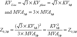
The above derivation proves that base impedance calculated for a 3-phase system is equivalent to base impedance calculated for a single phase. Hence, per unit method performs power system calculations on a single-phase basis.
Example 6.8
Consider the power system shown in Figure 6.3(a). Choosing appropriate base values convert the diagram into per unit reactance diagram. Use the data given in the table.

Fig 6.3(a) Single-Line Diagram of a Power System Network
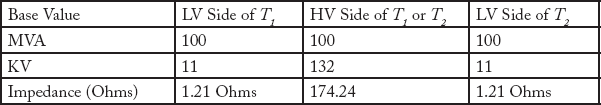
Per unit reactances:
- Generator G1 is on the LV side of T1.

- Generator G2 is on the LV side of T2.
%XG2 = 10% on 50 MVA, 11 KV base
or per unit reactance of G2 = 0.1 p. u
per unit reactance of G2 on selected base values of 100MVA, 11KV is: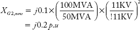
- Transformer T1:

Using the LV side base values of T1,
the per unit reactance value is :

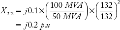
- Transformer T2:
XT2 = j0.1 p.u on 132KV or 11KV and 50MVA
XT2 on the selected base values 132 KV or 11KV and 100MVA is:
- Transmission lines (L1 and L2) are on HV side of T1 or T2. Hence using the corresponding base values, the p. u reactance is:
The per unit reactance diagram is shown in Figure 6.3(a)
6.4 Symmetrical Fault Caculation
Computation of three-phase fault currents is quite an easy process as calculations are carried out on a single-phase basis. The computation needs knowledge of:
- Converting electrical quantities into per unit values and
- Converting per-unit single-line diagram into Thevenin's equivalent circuit across the faulted point terminal and the ZPB terminal.
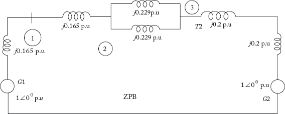
Fig 6.3(b) p. u. Reactance Diagram
6.4.1 Thevenin's Equivalent Circuit
Let a three-phase fault occur at the ith bus in a power system. Reduce the per unit reactance diagram into Thevenin's equivalent circuit across the faulted ith bus and the neutral (ZPB) as shown in Figure 6.4. In the figure, XTh is the Thevenin's equivalent reactance expressed in per unit value.
Let ISC be the short circuit current. The value of ISC is limited by XTh.
Define the base values as:
Base voltage V = Rated voltage E
Base current I = Full load or rated current
Base Impedance ![]()
Thevenin's equivalent reactance in per unit is given by
Rewriting the above,
By substituting V = E in the Equation (6.4) and using the above equation, it can be written as:
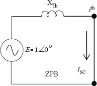
Fig 6.4 Thevenin's Equivalent Circuit
Note:
The ratio of rated current I to short-circuit ISC, gives the per unit reactance of the equipment.
% reactance is given by:
Rewriting the Equation (6.6) as
Multiplying both sides of Equation (6.7) with rated (or base) voltage
Equation (6.8) can be written as
The above equation is a useful formula to determine short-circuit KVA.
6.4.2 Calculation of Symmetrical Fault Currents
Procedure for the calculation of symmetrical fault involves the following steps:
- Choose convenient base values.
- Convert all the actual values into per unit values
- Convert the single-line diagram into per unit reactance diagram.
- Indicate the fault location.
- Reduce the p. u reactance diagram into Thevenin's equivalent reactance diagram.
- Finally, calculate short-circuit KVA using common base and % Thevenin's equivalent reactance using Equation 6.9.
Example 6.9
A 3-phase 10MVA, 11KV alternator has 10% sub-transient reactance. Find short circuit MVA and current, if a symmetrical fault occurs at its terminals.
Solution:
Take the alternator ratings as base values.
Base MVA 5 10MVA
Base KV 5 11KV

Example 6.10
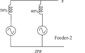
Two 11KV, 3-phase, 5MVA generators having sub-transient reactance of 3% and 2% respectively operate in parallel. Suppose the power loaded through a 11/220 KV, 10MVA transformer has % equivalent reactance of 4%. Calculate fault current and fault MVA for there-phase occurring on the H.T side of the transformer as shown in Figure 6.5(a). Also calculate the fault MVA supplied by each generator.
Solution:
Let common base MVA = 10
Base voltage for LT side of the transformer = 11KV
Base voltage for HT side of the transformer = 220KV
The % reactance of generators on selected base values are:
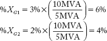
The reactance diagram is shown in Figure 6.5(b)
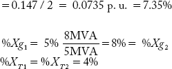
Thevenin's equivalent % reactance is


Fig 6.5(a) Power System Network of Example 6.10
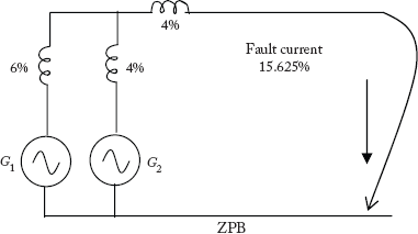
Fig 6.5(b) p. u. Equivalent Reactance Diagram
Using the current division formula,

Example 6.11
Two generators rated 11KV, 5000KVA having 5% reactance are interconnected by a transmission line of length 50 kms. The reactance of the line is 0.4 ohms/phase/km. Generators are connected to the line through a step-up transformer rated 11KV/33KV, 8000KVA and having 4% reactance. A three-phase fault occurs at the middle of transmission line. Calculate the fault MVA and current. Neglect load current.
Solution:
Selection of Base values
Common Base MVA = 8 MVA = 8000 KVA
Base KV (LT side) = 11 KV
Base KV (HT side) = 33 KV
Base impedance (HT side) ![]()
Total reactance of the line = 50 kms × 0.4 Ohms/phase/km = 20 Ohms
p. u. reactance of the line ![]()
p. u. reactance of the line up to the fault location
The reactance diagram is shown in Figure 6.6(b)
Thevenin's equivalent % reactance across the fault terminals is
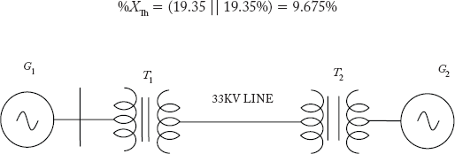
Fig 6.6(a) Power System Network of Example 6.11
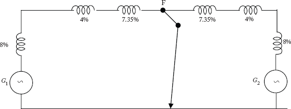
Fig 6.6(b) p. u. Equivalent Reactance Diagram
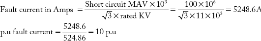
Short-circuit MVA at the fault location
Short-circuit current at the fault location
6.5 Current-Limiting Series Reactors
The extent of short-circuits at different locations can be reduced by connecting current-limiting reactors also known series reactors. A series reactor is an inductive coil having a large inductance with negligible resistance. These reactors are designed without saturation problems. By designing the reactance of the series reactor to a suitable value, short-circuit currents can be reduced to such a level where circuit breakers can handle them quite easily. As the present day power system is largely interconnected, a fault at a particular location is contributed to by the large number of generators. These unacceptable short-circuit levels can be easily adjusted to an acceptable value by using series reactors.
Types of series reactors:
Depending upon the location at which the series reactor placed, these can be divided into:
- Generator reactors
- Feeder reactors
- Bus bar reactors
6.5.1 Generator Reactors
Generator reactors are connected between the generator and the generator bus. The present-day generators are designed to have high reactance. Therefore, under dead three-phase fault condition of generator, the fault current is limited by its own reactance and hence generator reactors become unnecessary. However, older generators may require them. It is not a common practice to use separate reactors for each generator due to the following disadvantages.

Fig 6.7 Generator Reactors
Disadvantages
- Due to load variations, the generator terminal voltage fluctuates rapidly leading to a voltage drop in the series reactor.
- Continuous reactive power loss
- Bus bar voltage drops due to a short-circuit in any one feeder. Hence, healthy feeders experience low voltage problems.
- Generators may loose synchronism.
6.5.2 Feeder Reactors
In this case, each feeder is equipped with a series reactor as shown in Figure 6.8
Advantages
- Common bus bar voltage is unaffected by short-circuit in any feeder.
- As voltage drop is restricted to the respective feeders, the generators which are connected to common bus bars have least tendency to lose synchronism.
- Feeder reactors are commonly used, as faults occur more frequently on feeders.
Disadvantages
- As the power system has a large number of feeders, there is a requirement for more reactors.
- No short-circuit protection for generators and bus bars.

Fig 6.8 Feeder Reactors
6.5.3 Bus Bar Reactors
These reactors are connected to the bus bars as shown in Figure 6.9. Use of bus bar reactors avoids continuous voltage drop and power loss. This is because power flow through the reactor is small. It can be seen from the figure that if fault occurs on any one feeder, the generator connected to the feeder feeds the fault directly, whereas other generators feed the fault through bus bar reactors.
Types of Bus Bar reactors
Bus bar reactors can be connected in two ways to avoid power loss and voltage drop across the system under normal conditions.
- By Sectionalizing Bus Bar Reactors
In this method, the bus bar is divided into a number of sections. Each section is provided with one bus bar reactor as shown in Figure 6.10. Power loss is minimized as each generator supplies less power to other section feeders. If a fault occurs on any one feeder, the generator connected in this section feeds the fault directly, while other generators feed through bar reactors. Due to this, only that section of the bus bar connected to the feeder is affected, while other sections continue to function normally. - By Sectionalizing Bus Bars (Tie Bar System)
In this method we use two bars, namely, local bus bar and group bus bar as shown in Figure 6.11.
This method reduces the reactance value that is required for bus bar reactors. It can be understood with the help of Figure 6.11 that fault on a particular feeder does not affect other generators.

Fig 6.9 Bus Bar Reactors
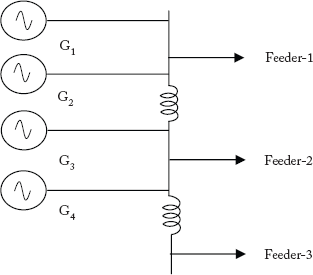
Fig 6.10 Sectionalized Bus Bar
Advantages
- New generator can be connected to the system without many modifications in the bus bar system.
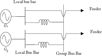
Fig 6.1 Sectionalizing of Bus Bars
- When new generators are connected, the reactors of the old generator need no replacement.
The only disadvantage of this method is the requirement of an additional bus bar.
Example 6.12
Figure 6.12 shows the single-line diagram of a power system. The % reactance of the generators is calculated by taking their ratings as base values. Calculate the short-circuit KVA if a 3Φ fault occurs on the feeder at the beginning. If the short circuit KVA has to reduce to 50% of that obtained earlier, then find the % reactance of feeder reactor.
Solution:
Common base MVA = 20.
![]()
The reactance diagram is shown below:

Fig 6.12 Power System Network of Example 6.12
Thevenin's equivalent resistance ![]()
- Short circuit MVA
- The reactance diagram is modified as shown by accommodating the feeder reactor.

Short circuit MVA = 50% of earlier value = 45 MVA

Base impedance ![]() Example 6.16
Example 6.16
Xsc 5 0.2222 p.u × 6.05 = 1.344 Ohms
Example 6.13
A 3-phase 100 MVA, 10KV alternator has 5% reactance. Find the external reactance per phase to be connected in series with the alternator so that three-phase short-circuit does not exceed eight times the full load current.
Solution:
Full load current of alternator

Therefore %Xse = % reactance of series reactor = 7.5%
The formula for % reactance is:
Where I = full load current
V = rated voltage per phase
From the above, the value of series reactor in Ohms is
Example 6.14
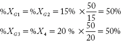
A power plant has four generators. Two generators rated 15 MVA have a reactance of 15%, and the other two rated 20MVA have 20% reactance. These generators are connected to station bus bars. Power is drawn to the load centers through two power transformers rated 50MVA each and having % reactance of 10%. It is required to design circuit breakers with ratings that are to be provided at the LT and HT side of transformer. The system is shown in Figure 6.13.
Solution:
Let 50 MVA be taken as the common base MVA. The % reactance of the generators is recalculated for the new base MVA taken
Design of circuit break rating on LT side of transformer
To design CB rating on the LT side, a three-phase fault is shown on the LT side as shown in the figure. Other feeder and transformer reactances do not appear in the fault current path. Obviously, the Thevenin's equivalent reactance is given by
Therefore CB rating on LT side = short circuit MVA = ![]()
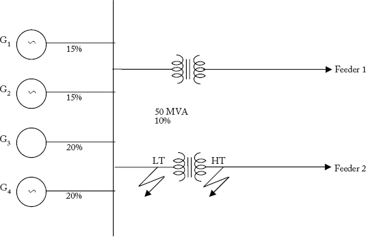
Fig 6.13 Power System Network for Example 6.14
Design of CB rating on the HT side:
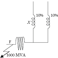
To design CB rating on the HT side, the fault has to be considered on the HT side as shown in the figure. Now, % reactance of the transformer comes in the way of fault current
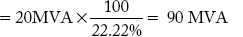
CB rating on the HT side = Short circuit MVA = 50 MVA × (100/22.5) = 222.22 MVA
Example 6.15
A generating station has four generators, each rated 11 KV, 100 MVA and each having a sub transient reactance of 10%. A sectionalized bus reactor is placed as shown in Figure 6.14. A three-phase fault occurred at a point near the bus as shown in the figure.
- Determine the fault level if % X = 0 ohm.
- Determine the X value in Ohms to limit the fault level to 3000 MVA

Fig 6.14 Power System Network for Example 6.15
Solution:
Common base MVA = 100
Base kV = 11kV
Base impedance = ![]() = 1.21 Ohms
= 1.21 Ohms
(a) The equivalent circuit to determine Thevenin's equivalent reactance is shown below.
The % X = 0 Ohms taking

(b) The generator G1 and G2 will supply MVA directly to the fault, the value of which is 50% of total fault, i.e., 2000MVA. Now, G3 and G4 have to supply 3000 – 2000 = 1000MVA fault power. Consider the following equivalent reactance diagram
Short circuit MVA = 1000 = 100 × 
Xtotal = ![]()
But %Xtotal = ((10% || 10%) + % X
From the above, % X = 5%
Therefore ![]()
Example 6.16
Particulars of three generators namely A, B and C are as follows.
GA: 11 KV, 40 MVA, X = 10%
GB : 11 KV, 60 MVA, X = 12%
GC : 11 KV, 25 MVA, X = 10%
Three generators are inter-connected as shown in Figure 6.15(a). The generators are provided with bus bar reactors, each having Xse = 10% reactance based on their ratings. A feeder directly connected to Generator A as shown in the figure has an impedance of Z = 0.05 + j 0.1 Ohms/phase. Estimate the short-circuit MVA if a symmetrical fault occurs at the far end of the feeder.
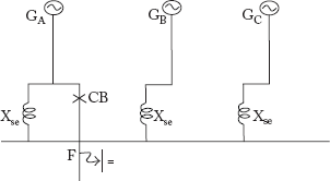
Fig 6.15(a) Power System Network of Example 6.16
Solution:
Let 60 MVA, 11 KV be common base values. The p. u. reactances based on common base values are computed below:
Generator A: XA = 10% = 0.1 p.u on 11 KV, 40 MVA

Generator B: XB = 0.12 p. u on 11 KV, 60 MVA
Generator C: ![]()
Series bus bar reactor
Feeder impedance Zbase= 0.05 + j0.1 Ohms /phase
Base impedance 
Feeder impedance in p. u

assuming that pre-fault current is zero (No Load).
The equivalent circuit is shown in Figure 6.15(b). The figure can be used to find Thevenin's equivalent reactance.
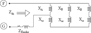
Fig 6.15(b) p. u. Equivalent Reactance Diagram

Finally, Thevenin's impedance:

Short-circuit MVA 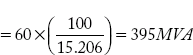
Example 6.17
Two power stations, namely, A and B have short-circuit capacities of 800 and 600 MVA respectively. Both are operating at 11 KV. Find the short-circuit MVA if they are interconnected by a cable of 0.4 Ohm reactance per phase.
Solution:
Using Equation (6.9) p. u reactance of the two stations can be obtained as below:
Let Base MVA = 100;
Base KV = 11;
p. u. reactance of 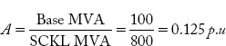
p. u. reactance of B = ![]()
Base impedance = ![]()
Cable reactance in p. u = 
The equivalent circuit is shown in Figure 6.16.

Fig 6.16 Power System Network of Example 6.17
It can be verified from Figure 6.16 that short circuit MVA is maximum when the fault occurs at point B.
Taking terminal-A and grand as terminals,
XTh = (0.166 || (0.125 + 0.3305)
= 0.122 p.u
Short-circuit MVA
6.6 Consideration of Pre-Fault Load Current
Short-circuit currents are several times more than pre-fault load currents and hence neglected. If load currents are large they may be required to be considered in short-circuit analysis. In addition, if a large number of synchronous motors are working in the system, under faulty conditions they feed power to the fault momentarily before the circuit breaker operates, working as synchronous generators with available kinetic energy in the rotor. As there is a separate field system available, the case is not applicable to induction motors. The exact fault current in this case can be obtained by superimposing load current on fault current through the use of super position theorem.
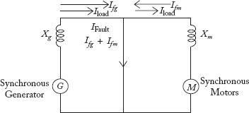
Fig 6.17 Consideration of Pre-Fault Load Current
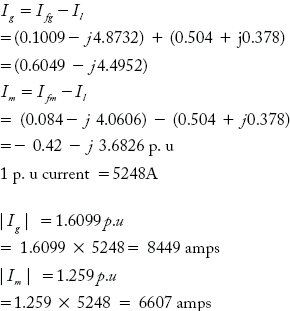
It can be seen in Figure 6.17 that under faulty conditions,
- The generator current is the vector sum of Ifg and ILoad
- The synchronous motor current is the vector difference between Ifm and ILoad
- Fault current flowing into the fault is the vector sum of Ifg and Ifm
where Ifg = Component of fault current supplied by the generator
Ifm = Component of fault current supplied by the synchronous motor
ILoad = Pre-fault load current supplied from generator to motor
Example 6.18
A synchronous generator is supplying 60MVA power to a synchronous motor through a transmission line. Numerical data of the equipment depicted in Figure 6.18(a) are per unit values computed on common base values of 100MVA, 11KV.

Fig 6.18(a) Power System Network of Example 6.18
Motor is drawing 50MW at 0.8 P. f (lead). Terminal voltage of the motor is 10.9 KV. Now, a 3-phase fault occurs in Bus-1 as shown in the figure. Considering the pre-fault load current, compute the total generator and motor currents under faulty conditions.
Solution:
The equivalent circuit is shown in Figure 6.18(b)
Base MVA = 100; Base KV = 11;
Base current = ![]()
Terminal voltage of the motor = 10.9KV
Power drawn by the motor = 50 MW
Load current 
Load current in p. u
Let the receiving end voltage (motor terminal) be taken as reference

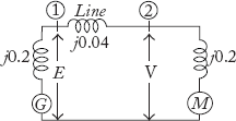
Fig 6.18(b) p. u. Equivalent Reactance Diagram
Motor terminal voltage in p. u ![]()
Generator terminal voltage
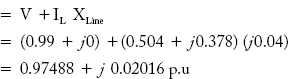
Thevenin's equivalent voltage = Pre-fault voltage across generator terminals = 0.97488 + j0.02016 p.u
Thevenin's equivalent reactance across fault terminals 1 and ground G terminals from Fig 6.18(c) is:
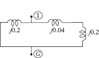
Fig 6.18(c) Thevenin's Equivalent Circuit
Total fault current = ![]()
Using current division formula, fault current supplied by the generator is

Total fault current supplied by the generator and motor is:
Questions from Previous Question Papers
- What is the importance of base KVA in short-circuit calculations?
- A generating station has four bus bar sections. Each section is connected to the tie bar through 20% reactors rated at 200MVA. Generators of total capacity 100MVA and 20% reactance are connected to each bus bar section. Calculate the MVA fed to a fault under short-circuit condition on two of the bus bars.
- (a) Explain the harmful effects of short-circuit faults on the power system.
(b) Two generators are connected to a common bus bar at which an outgoing feeder is connected. The generator ratings are 15MVA, 30% and 20MVA, 50% respectively. The percentage reactance of each alternator is based on its own capacity. The bus bar voltage is 12KV. Find the short-circuit current that will flow into a complete 3-φ short-circuit at the beginning of the outgoing feeder.
- (a) What are the direct symmetrical faults and compare their properties?
(b) The section bus bar A and B are linked by a bus bar reactor rated at 5000KVA with 10% reactance. On bus bar A there are two generators, each of 10,000KVA with 10% reactance and on bus bar B there are two generators, each of 8000KVA with 12% reactance. Find the steady MVA fed into a dead short-circuit between all phases on A and B with bus bar reactor in the circuit.
- (a) Why do you use a single-line diagram for power system representation? What are the assumptions that are being made while drawing a single-line diagram?
(b) A transmission line of inductance 0.1 H and resistance 5 Ω is connected to a source of V = 100 sin (ωt + 150), f = 50 Hz at one end and the other end is suddenly short circuited at t = 0 at the bus bar end. Write the expression for the short circuit current i(t). Find approximately, the value of the first current maximum.
- (a) Explain the need for per unit method in power system calculations.
(b) Explain how base quantities can be selected, and derive the formula for base impedance.
- What is the per unit system? Why it is required in power system calculations?
- Explain how base values can be selected in the networks containing transformers.
- Explain how base quantities can be selected and derive the formula for base impedance.
- Why do you a single line diagram for power system representation. What are the assumptions that are made while drawing a single line diagram.
- By choosing the rating of transformer as base values, convert all electrical quantities of the following transformer is rated as 100KVA, 2000/200 V, single phase has equivalent impedance referred to H.V. side as (1 + j1) ohm and exciting current referred to LV side is 3 Amps.
- For the power shown in Figure Q1, draw the equivalent reactance diagram by selecting generator as the base values.
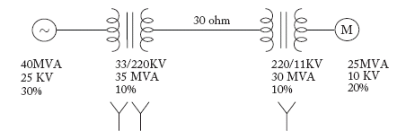
Fig Q1
- Figure Q2 shows two generators are connected to a common bus bar, at which an outgoing feeder is connected. The generator ratings are 15 MVA, 30% and 20 MVA, 50% respectively. The % reactance of each alternator is based on its own capacity. The bus bar voltage is 12 KV. Find the short circuit current that will flow into a complete 3-phase short circuit at the beginning of the outgoing feeder.
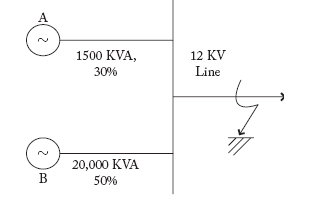
Fig Q2
- A generating station has four bus bar sections as shown in Figure Q3. Each section is connected to tie bar through 20% reactors rated at 200MVA. Generators of total capacity 100MVA and 20% reactance
are connected to each bus bar section. Calculate the MVA fed to a fault under short-circuit condition on two of the bus bars.
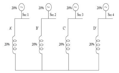
Fig Q3
- The section bus bar A and B are linked by a bus bar reactor rated at 5000 KVA with 10% reactance. On bus bar A there are two generators each 10,000KVA with10% reactance and on B two generators each of 8000 KVA with 12% reactance. Find the steady MVA fed into a dead short circuit between all phases A and B with bus bar reactor in the circuit.
- Explain the harmful effects of short circuit fault on the power system.
- Why do we use series reactors in the power system? Discuss their advantages.
- Explain the various methods of connecting current limiting series reactors
- The plant capacity of a 3-phase generating station consists of two 8MVA generators of reactance 14% each. These are connected to a common bus bar from which loads are taken through a 5MVA, 11/33 KV step up transformer having 4% reactance. Determine the MVA ratings of the circuit breakers, when a symmetrical 3-phase fault occurs at the LV side of the transformer. The reactances given are based on MVA of each equipment.
- The plant capacity of a 3-Phase generating station consists of two 10MVA generators of reactance 14% each. These are connected to a common bus-bar from which loads are taken through two 3MVA, 11/33 KV setup transformer each having 5% reactance. Determine the MVA rating of the circuit breakers, when a 3-phase symmetrical fault occurs at the HV sides of two transformers. The reactances given are based on the MVA of each equipment.
Competitive Examination Questions
- The impedance value of a generator is 0.2 p. u on a base value of 11KV, 50MVA. The impedance value for a base value of 22KV, 150MVA is
- 0.15 p. u
- 0.2 p. u
- 0.3 p. u
- 2.4 p. u
- In a power system with negligible resistance, the fault current at a point is 800 p. u. The series reactance to be included at the fault point to limit the short circuit to 5.00 p. u. is
- 3.00 p. u
- 0.200 p. u
- 0.125 p. u 8
- 0.075 p. u
- When a line-to-ground fault occurs, the current in a faulted phase is 100A. The zero sequence in this case will be
- 0
- 33.3A
- 66.6A
- 100A
- The p. u impedance of a synchronous machine is 0.242. If the base voltage is increased 1.1 times, the p. u value will be
- 0.266
- 0.242
- 0.220
- 0.200
- The system is on no-load when a 3-ф fault occurs at ‘F’ on the high voltage side of the transformer T2. The fault current will be
- –j0.8187 p. u
- j0.8187 p. u
- –j8.187 p. u
- j8.1871 p. u
- An isolated synchronous generator with transient reactance of 0.1 p. u on a 100MVA base is connected to a high voltage bus through a step-up transformer of reactance 0.1 p. u on a 100MVA base. The fault level at the bus is
- 1000MVA
- 500MVA
- 50MVA
- 50MVA
- The p. u impedance of a circuit element is 0.15. If the base KV and base MVA are halved, then the new value of the p. u impedance of the circuit element will be
- 0.075
- 0.15
- 0.30
- 0.60
- The p. u impedance of an alternator corresponding to base 13.2 KV, 30MVA is 0.2 p. u. The p. u value of the impedance for base values 13.8KV and 50 MVA is
- 0.131
- 0.226
- 0.305
- 0.364
- For a given base voltage and base volt-amp, the p. u impedance value of an element is X. What will bet the p. u impedance value of this element when the voltage and volt-amp bases are both doubled?
- 4X
- 2X
- X
- 0.5X
- Four identical 100MVA, 33KV generators are operating in parallel as shown, in two bus bar sections interconnected through a current limiting reactor of X p. u reactance on the generator base. Each generator has a reactance of 0.2 p. u. The value of the reactor is 0.2 p. u. The value of reactor X to limit a symmetrical short-circuit (a-b-c) current through the circuit breaker to 1500 MVA is
- 0.05 p. u.
- 0.10 p. u
- 0.15 p. u
- 0.20 p. u
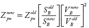
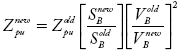
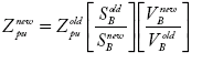
- Zpuold is the p. u impedance on the power base SBold and voltage base VBold .What would be the p. u. impedance on the new power base SBnew and Voltage base ZBnew?
Which of the following are correct?
- 2 and 3
- 1 and 2
- 1 and 3
- 1, 2 and 3
- Match List-1 with List-2
List — 1 List — 2 (Type of element) (Application) 1. Series Reactor A. Power Factor 2. Shunt Reactor B. Stability 3. Series Capacitor C. Ferranti Effect 4. Shunt Capacitor D. Faults - 1A, 2B, 3C, 4D
- 1D, 2C, 3B, 4A
- 1D, 2C, 3A, 4B
- 1D, 2B, 3C, 4A
- Circuit breaker rating is designed based on the following fault current
- LG
- LLG
- LL
- 3-Phase
- The p. u. fault current at a fault location is 10 p. u. The series reactor reactance value that is required to reduce fault current to 2 p. u is
- 0.1 p. u
- 0.3 p. u
- 0.4 p. u
- 0.5 p. u
- The bus bars of two alternators of 10% reactance each are interconnected through a tie bar reactor of 20% each. The short-circuit current in p. u if a 3-phase fault occurs on any alternator bus bar is
- 10 p. u
- 12 p. u
- 15 p. u
- 20 p. u
- The p. u. impedance of a synchronous machine is 0.25p. u. The machine is rated 10MVA. The short-circuit capacity of the machine is
- 25 MVA
- 40MVA
- 50MVA
- 100MVA
- The symmetrical fault current at the fault location F is
- 5p. u
- 6p. u
- 7p. u
- 15p. u

- A 500 MVA, 11 KV synchronous generator has 0.2 p.u. synchronous reactance. The p.u. synchronous reactance on the base values of 100 MVA and 22 KV is:
- 0.16
- 0.01
- 4.0
- 0.25
[GATE 1991 Q.No. 1]
- In the power system circuit diagram shown in figure, the current limiting reactor X is to be chosen such that the feeder breaker rating does not exceed 425 MVA, The system data is as follows:
Feeder transformer reactance: 10% on 50 Mva base.
The generating source A, B, C have individual fault levels at 1000 MVA with respective generator breakers open. Ignore pre-fault currents and assume 1.0 p.u. voltages throughout before fault. Assume common base of 1000 MVA.
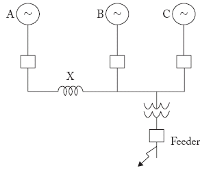
[GATE 1996 Q.No. 10]
- The synchronous reactance of a 200 MVA, 10 kv, 3-phase, 50 Hz generator is 1.0 p.u. at its own base. Its p.u. reactance at 100 MVA, 20 kv base will be ……………………
[GATE 1997 Q.No. 9]
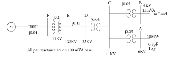
- The system shown in figure feeds two loads — (a) a factory load of 15 MVA consisting of induction motors and (b) a domestic load of 10 MW at 0.8 p.f. lagging at 6 kV. If the induction motors are rated at 6 kv and take 5 times their rated current at zero p.f. at starting, calculate the dip in voltage at the domestic load bus bar when all the induction motors are started at the same time.
[GATE 1997 Q.No. 10]
- Series capacitive compensation in EHV transmission lines is used to
- reduce the line loading
- improve the stability of the system
- reduce the voltage profile
- improve the protection of the line
[GATE 1998 Q.No. 2]
- A 10 kVA, 400 V/200V single-phase transformers with 10% impedance draws a steady short circuit line current of
- 50 A
- 150 A
- 250 A
- 350 A
[GATE 1999 Q.No. 12]
- Determine the required MVA rating of the circuit breaker CB for the system shown in figure. Consider the grid as infinite bus. Choose 6 MVA as base.
Transformer: 3-phase, 33/11 kV, 6 MVA,0.01+ j0.08 p.u. impedance.
Load: 3-phase, 11 kv, 5800 MVA, 0.8 lag, j0.2 p.u. impedance.
Impedance of each feeder 9 + j18Ω
[GATE 1999 Q.No. 15]
- For a given base voltage and base volt-amperes, the per unit impedance value of an element is x. What will be the per unit impedance value of this element when the voltage and volt-ampere bases are both doubled?
- 0.5x
- 2x
- 4x
- x
[GATE 2000 Q.No. 2]
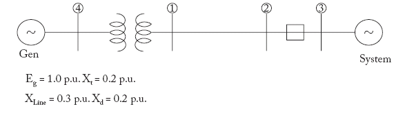
- For the configuration shown in figure, the breaker connecting a large system to bus 2 is initially open. The system 3-phase fault level at bus 3 under this condition is not known. After closing the system breaker, the 3-phase fault level at bus 1 was found to be 5.0 p.u. What will be the new 3-phase fault level at system bus 3 after the interconnection? All per unit values are on common bases. Prefault load currents are neglected and prefault voltages are assumed to be 1.0 p.u. at all buses.
[GATE 2000 Q.No. 13]
- A 3-phase transformer has rating of 20 MVA, 220 kv (star) — 33kv (delta) with leakage reactance of 12%. The transformer reactance (in Ohms) referred to each phase of the L.V. delta-connected side is
- 23.5
- 19.6
- 18.5
- 8.7
[GATE 2001 Q.No. 3]
- A 75 NVA, 10 kV synchronous generator has Xd = 0.4 p.u. The Xd value (in p.u.) is a base of 100 MVA, 11 kV is
- 0.578
- 0.279
- 0.412
- 0.44
[GATE 2001 Q.No. 4]
- A 3-phase generator rated at 110MVA, 11 kV is connected through circuit breakers to a transformer. The generator is having direct axis sub-transient reactance X''d = 19%, transient reactance X'd = 26% and synchronous reactance=130%. The generator is operating at no load and rated voltage when a three-phase short circuit fault occurs between the breakers and the transformer. The magnitude of initial symmetrical rims current in the breakers will be
- 4.44 kA
- 22.20 kA
- 30.39 kA
- 38.45 kA
[GATE 2004 Q.No. 11]
- The p.u. parameters for a 500 MVA machine on its own base are:
inertia M = 20 p.u.; reactance x = 2 p.u.
The p.u. values of inertia and reactance on 100 MVA common base, respectively, are
- 4, 0.4
- 100, 10
- 4, 10
- 100, 0.4
[GATE 2005 Q.No. 1]
- Two generating stations G1 and G2 of ratings 10 MVA and 8 MVA respectively are linked by a line rated at 5 MVA, 0.1 pu reactance. Each station has a reactance of 0.5 pu. If the base MVA is 10 MVA, short-circuit MVA of G1 is
- 36.6
- 34.28
- 32.15
- 10
[JTO 2009 Section II, Q.No. 38]