
CHAPTER 3
Power System Network Matrices—2
3.1 Introduction
In the previous chapter, we have discussed the methods for formulating ZBus either directly or through the inversion of YBus. These topological methods, though effective for small-sized networks, have the following disadvantages when applied to large networks such as a real power system:
- For a large-sized power system, the dimension of YBus is very high. Inversion of such large size matrices may have computational difficulties.
- Network changes such as outage of lines, addition of lines and disconnection of sources are frequent. For these changes, the topology or the structure of the network is not the same and we shall have to formulate of network matrices from the beginning again. This procedure is unnecessary and is rather wasteful.
- The computational effort in constructing ZBus by adding one element at a time is much greater than that required to construct YBus. However, ZBus furnishes more information regarding the network, as is evident from the non-zero elements (zero sparsely) present in the ZBus matrix. Further, if the network contains open circuits such as those in the zero sequence network of the system, then some zero elements may be present. Otherwise ZBus is never sparse.
Bus admittance matrix has been used in power flow studies (discussed in Chapter-4) because of its sparsity advantages, whereas the bus voltages are explicitly expressed in terms of bus currents using the bus impedance matrix in short-circuit studies (Chapter-6).
This chapter presents an algorithm for building up the bus impedance matrix in a step-by-step procedure (adding one element at a time). In this building up algorithm, modifications required in ZBus can be easily incorporated in accordance with the network changes.
3.2 Partial Network
A partial power system network is a linear passive inter-connected network with all passive elements being thoroughly connected to form a complete network. However, some or all the buses are available outside as shown in Figure 3.1.
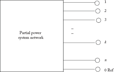
Fig 3.1 n-Bus Partial Power System Network
The performance equations in the bus-frame of reference can be written as:
and represent n-number of system equations for an n-bus power system.
The matrix ZBus is a symmetric square matrix of dimension (n 3 n) and is given below:

The performance equations are:

Procedure for finding the elements of ZBus:
To find the diagonal elements Zii, we inject Ii = 1 p.u current at the ith bus and open all remaining buses such that all Ik's are zeros for k = 1, 2,…, n but k ≠ i (See Figure 3.2). Since Ii = 1 p.u current, measurement of the ith bus voltage with respect to the reference bus directly gives the value of Zii as:
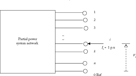
Fig 3.2 Determination of Diagonal Elements in ZBus

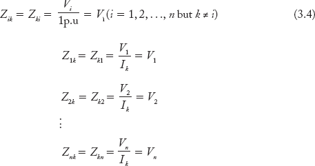
To find the off-diagonal elements Zik, inject 1 p. u current at the kth bus and keep the remaining buses open such that all Ii's are zeros for i = 1, 2,…, n but i ≠ k. Since Ik = 1 p. u the measurement of the ith bus voltage (I = 1, 2, …, n but i ≠ k) shall give directly the value of Zik as:
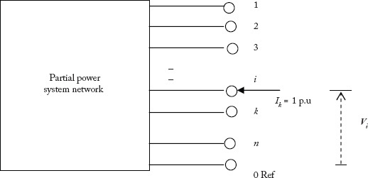
Fig 3.3 Determination of Off-Diagonal Elements in ZBus
The following sections present the algorithm for building up ZBus by adding only one element at a time, in a step-by-step process. This procedure can be programmable and has the advantage of not requiring a complete rebuilding of the ZBus for any modification of the network.
3.3 Case Studies in ZBus ALGORITHM
For an existing n-bus partial connected power system network, the ZBus would have been previously formulated. Let this be designated as ZBus-Old and is given by Equation (3.1), which is repeated below for convenience.

Whenever a new element is added or removed, the matrix modifies ZBus-Old to ZBus-New. We shall now discuss modifications to the ZBus algorithm in the following cases. First, we consider the modifications in ZBus when an element is added to the existing network.
Case-1: Whenever a branch (or twig) element is added, either a new bus (or node) is created. This increases the dimension of ZBus-New to (n + 1 3 × n + 1), i.e, by one row and one column, over ZBus-Old. The elements of the new row and column need to be determined.
Case-2: Whenever a link element is added, the dimension of ZBus remains the same. However, some of the elements of ZBus-Old matrix related to the link elements need to be modified to obtain ZBus-New.
Each of the above two cases can be further subdivided into four types:
Type-1: The added element is a branch element between a new bus and the reference bus.
Type-2: The added element is a branch element between an existing old bus (other than the reference bus) and a new bus.
Type 3: The added element is a link element between the reference bus and an existing old bus.
Type-4: The added element is a link element between two existing old buses other than the reference bus.

Fig 3.4 Various Cases in ZBus Algorithm
Further, the added element may or may not have mutual coupling with the already existing elements in the partial network. Figure 3.4 depicts all the above cases in building up the algorithm for ZBus.
3.4 Algorithm for Formation of Bus Impedance Matrix — No Mutual Coupling between the Elements
This section presents the four type-modifications in the partial network and describes the consequent modifications in the ZBus. A simple case of 2-bus partial network is chosen for better understanding of the algorithm. However, the modifications are later generalized for large-sized n-bus power system.
3.4.1 Type-1 Modification
The performance equation for a 2-bus partial network Figure (3.5) can be written as:
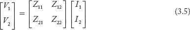
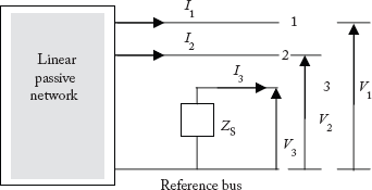
Fig 3.5 Type-1 Modification (No Mutual Coupling)
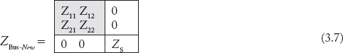
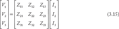
A branch element with self-impedance Zs is added between the new bus (3) and the reference bus (0). Since the added element is a branch, the size of ZBus increases from 2 × 2 to 3 × 3 and Equation (3.5) is modified to:

To find the diagonal element Z33, induce I3 = 1 p. u current into the third bus, and open buses 1 and 2 (I1 and I2 = 0).
To find the off-diagonal elements, we first induce I1 = 1 p.u (I3 and I2 = 0) and later I2 = 1 p. u (I3 and I1 = 0) and measure voltage V3. Since current in the buses cannot affect the voltage V3, we can write the off-diagonal elements as:
Now, the modified ZBus is:
Type-1 modification for the existing n-bus partial network is given below.
For the added branch with impedance Zs between the new bus (k) and the reference bus (0), as:

3.4.2 Type-2 Modification
The branch element with self-impedance Zs is added from the new bus 3 to the old bus 2.
With reference to Figure 3.6, the bus voltages are:

Fig 3.6 Type-2 Modifications
Substituting (3.11) in (3.12) we obtain:
Rearranging the above equation,
Equations (3.10), (3.11) and (3.14) give the new matrix as:
where Z13 = Z12, Z31 = Z21, Z23 = Z22, Z32 = Z22, Z33 = Z22 + Zs
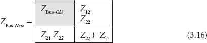
In the generalized form the above Equation (3.16) can be rewritten for the added branch with impedance Zs between the new bus k and the old bus j as:
3.4.3 Type-3 Modification
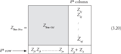
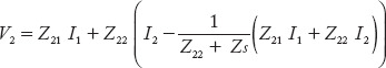
Let a link element with self-impedance ZS be added between bus 2 and reference bus 0 as shown in Figure 3.7. This can be treated as an extension of Type-2 modification by introducing a new bus 3. However, bus 3 is eliminated later by setting V3 = 0 (node elimination technique). The modified performance equation can be written as:

where Z13 = Z12, Z31 = Z21, Z23 = Z22, Z32 = Z22, Z33 = Z22 + ZS
Node elimination technique
Set V3 = 0 by closing the switch in Figure 3.7. By setting V3 = 0 in equation in Equation (3.21),


Fig 3.7 Type-3 Modification
Substituting the value of I3 in (3.10)
By rearranging the terms in the above equation,
and the values of I3 in Equation (3.11), we get
By rearranging the terms in the above equation,
Equations (3.23) and (3.24) can be written in the matrix form, as:
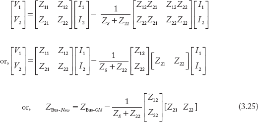
Let Equation (3.25) be written in a more generalized form. Assume that an element with self-impedance Zs is added between the old bus k and the reference bus in an n-bus partial power system network.

Any general term in the Equation (3.26) can be written as:
3.4.4 Type-4 Modification
A link element with self-impedance Zs connects old bus 2 to old bus 3 as shown in Figure 3.8. Referring to the figure, we can write performance equations as:


Fig 3.8 Type-4 Modification
The voltages of the buses 2 and 3 can be written as:
or
Z31 I1 + Z32 (I2 + I4) + Z33 (I3 – I4) = Z21 I1 + Z22 (I2 + I4) + Z23(I3 – I4) + ZS I4
Rearranging, the above equation
0 = (Z21 – Z31) I1 + (Z22 – Z32) I2 + (Z23 – Z33) I3 + (Z22 + Z33 – Z23 – Z32 + ZS) I4
or,
where Zx = (Z22 + Z33 – Z23 – Z32 + ZS)
I4 in the matrix form can be written as

Separating I4 terms in the matrix Equation (3.27) can be written as:

Substituting the value of I4 from Equation (3.29) in Equation (3.30),
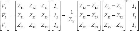
Extracting ZBus-New from the above equation, it can be written as:

Let Equation (3.31) be written in a more generalized form. Assume an element with self-impedance Zs be added between the old buses i and k in an n-bus partial power system network.
Let a link element with self-impedance Zs be added between two existing old buses, say k and l
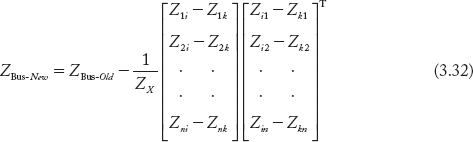
where, ZX = ZS + Zii + Zkk – Zik – Zki.
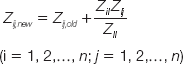
Any general pth row—qth column element in the modified matrix is:
3.4.5 MATLAB Program for Zbus Formation
Students may use MATLAB function Zbus to verify the results of numerical problems. While executing the program the input data is entered under the matrix variable “nw_data”.
It is required to take the reference bus as 0.
% This program was developed by Dr. N.V.RAMANA
% On command prompt enter nw_data
% Calculate zbus by building algorithm
function zbus = zbus_nvr(nw_data)
resistance = nw_data(:,3);
reactance = nw_data(:,4);
elements = length(nw_data(:,1));
rb = 0;
cb(1)=[0];
z = zeros(elements,1);
h = sqrt(—1);
z = resistance+ reactance*h;
fb = nw_data(:,1);
tb = nw_data(:,2);
nodes = max(max(fb),max(tb));
zbus = zeros(nodes,nodes);
for i=1:elements
nb = max(fb(i),tb(i));
ob = min(fb(i),tb(i));
m = length(cb);
zs = z(i);
if (ob = rb)
link = 0;
branch = 0;
for ii = 1:m
if nb — cb(ii) == 0
link = 1;
else,
end
end
if link == 0
branch = 1;
cb = [cb nb];
else,
end
if branch == 1
m=length(cb);
for ii=1:m — 1
zbus(ii,nb) = 0;
end
zbus(nb,nb)=zs;
else
end
if link == 1
zbold = zbus;
for i=1:m—1
for j=1:m—1
zbus(i,j) = zbold(i,j) — ((zbold(i,nb))*(zbold(nb,j))/(zbold(nb,nb) + zs));
end
end
else,
end
else,
end
if ob~ = rb
link1 = 0;
link2 = 0;
branch = 0;
for ii = 1:m
if cb(ii) — fb(i) == 0
link1 = 1;
else,
end
end
for ii = 1:m
if cb(ii) — tb(i)==0
link2 = 1;
else,
end
end
if link1 == 1 &link2 == 1
zbold = zbus;
for k=1:m-1
for j=1:m-1
zbus(k,j) = zbold(k,j) — ((zbold(k,ob) — zbold(k,nb))*(zbold(ob,j) — …
zbold(nb,j))/(zs+zbold(ob,ob)+zbold(nb,nb) — 2*zbold(ob,nb)));
end
end
else
if link1 == 1
for ii = 1:m
if cb(ii) — fb(i) == 0
ob = fb(i);
nb = tb(i);
cb = [cb nb];
else,
end
else,
end
if link2 == 1
for ii = 1:m
if cb(ii) — tb(i) == 0
ob = tb(i);
nb=fb(i);
cb = [cb nb];
else,
end
end
else,
end
m = length(cb);
for ii=1:m — 1
zbus(nb,ii) = zbus(ob,ii);
zbus(ii,nb) = zbus(ob,ii);
end
zbus(nb,nb) = zbus(ob,ob) + zs;
end
else,
end
end
end
Example 3.1
Obtain the bus impedance matrix for the power system network shown in Figure 3.9(a) when the line L5 is not connected between buses 1 and 3. Take reactance of each line as j0.2 p. u.
Solution:
Consider the graph for the network in Figure 3.9(b), that is, without L5 line.
Step 1: Add branch 1–2. This is a Type-1 modification.
Step 2: Add branch 2–3. This is a Type-2 modification.
Step 3: Add link between buses 2 and 3. This is a Type-4 modification. With a fictitious bus l the ZBus is:

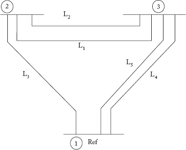
Fig 3.9(a) Power System Network for Example 3.1
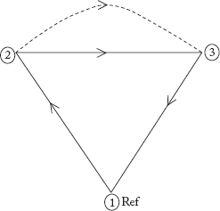
Fig 3.9(b) Graph of the Network shown in Figure 3.9(a)
where,
Now, the modified ZBus obtained by removing the fictitious bus l is:

Step 4: Add link L3. This is a Type-3 modification. With a fictitious bus l the ZBus is:
Now, the modified ZBus obtained by removing the fictitious bus l is:
Note: As the reference bus should be 0, observe buses are renumbered in the MATLAB program.
MATLAB RESULTS
nw_data =
0 1.0000 0 0.2000
0 2.0000 0 0.2000
1.0000 2.0000 0 0.2000
1.0000 2.0000 0 0.2000
zbus =
0 + 0.1200i 0 + 0.0800i
0 + 0.0800i 0 + 0.1200i
Example 3.2
If the line L5 in Figure 3.9(a) is added between the buses 1 and 3, modify the ZBus.
Solution:
The line L5 is another link added across buses 1 and 3. This is Type-3 modification. With a fictitious bus l the ZBus is:

The modified ZBus obtained by removing the fictitious bus l is:
Note: As the reference bus should be 0, observe buses are renumbered in the MATLAB program.
MATLAB RESULTS
nw_data =
0 1.0000 0 0.2000
0 2.0000 0 0.2000
1.0000 2.0000 0 0.2000
1.0000 2.0000 0 0.2000
0 2.0000 0 0.2000
zbus =
0 + 0.1000i 0 + 0.0500i
0 + 0.0500i 0 + 0.0750i
Note: The student is advised to refer to Section 3.6 to understand numerical examples that involve modifications in ZBus, where certain elements are removed.
Example 3.3
If the line L2 is removed between the buses 2 and 3 in Figure 3.9(a), modify the ZBus.
Solution:
If the line L2 in the figure is removed the modified ZBus can be obtained by adding a link in parallel with the element such that the impedance of the link added equals to the negative of the impedance of the element to be removed.
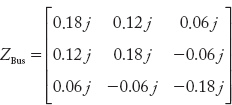
The actual ZBus of the network is:

Now, add a link across 2–3 with impedance j0.2 p. u. Type-4 modification with a fictitious bus l, the ZBus is:


The modified ZBus by removing the fictitious bus l is:
MATLAB RESULTS
nw_data =
0 1.0000 0 0.2000
0 2.0000 0 0.2000
1.0000 2.0000 0 0.2000
0 2.0000 0 0.2000
zbus =
0 + 0.1200i 0 + 0.0400i
0 + 0.0400i 0 + 0.0800i
Example 3.4
The positive sequence impedance of a power system network is shown in Figure 3.10(a). All reactance are in per unit system. Obtain the ZBus matrix by building an algorithm.
Solution:
The graph for the positive sequence impedance network is shown in Figure 3.10(b).
Step 1: Add branch 0–1, this Type-1 modification gives:
Step 2: Add branch 1–2, this Type-2 modification gives:
Step 3: Add branch 2–3, this Type-2 modification gives:

Step 4: Add branch 3–4, this Type-2 modifications gives:

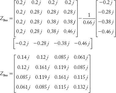
Step 5: Add link 0–4, this Type-3 modification gives:
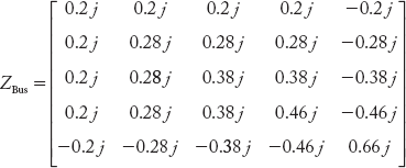
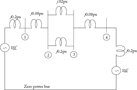
Fig 3.10(a) Power System Network for Example 3.4
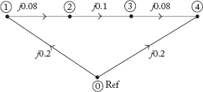
Fig 3.10(b) Graph for Figure 3.10(a)
Now, the modified ZBus obtained by removing the fictitious bus is:
MATLAB RESULTS
nw_data =
0 1.0000 0 0.2000
0 4.0000 0 0.2000
1.0000 2.0000 0 0.0800
2.0000 3.0000 0 0.1000
3.0000 4.0000 0 0.0800
zbus =
0 + 0.1394i 0 + 0.1152i 0 + 0.0848i 0 + 0.0606i
0 + 0.1152i 0 + 0.1612i 0 + 0.1188i 0 + 0.0848i
0 + 0.0848i 0 + 0.1188i 0 + 0.1612i 0 + 0.1152i
0 + 0.0606i 0 + 0.0848i 0 + 0.1152i 0 + 0.1394i
Example 3.5
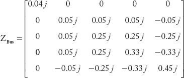
The zero sequence impedance of a power system network is shown in Figure 3.11(a). All reactance are in per unit. Obtain the ZBus matrix by building an algorithm.
Solution:
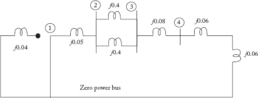
Fig 3.11(a) Zero Sequence Network for Example 3.5(a)
The graph for the zero sequence impedance network is shown in Figure 3.11(b)
Step 1: Add branch 0–1, this Type-1 modification gives:
Step 2: Add branch 1–2, this Type-1 modification gives:
Step 3: Add branch 2–3, this Type-2 modification gives:
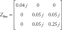
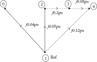
Fig 3.11(b) Graph of the Network
Step 4: Add branch 3–4, this Type-2 modification gives:
Step 5: Add link 1–4, this Type-3 modification gives:
Now, the modified ZBus obtained by removing the fictitious bus is:

MATLAB RESULTS
nw_data =
0 1.0000 0 0.0400
0 4.0000 0 0.1200
0 2.0000 0 0.0500
2.0000 3.0000 0 0.2000
3.0000 4.0000 0 0.0800
zbus =
0 + 0.0400i 0 0 0
0 0 + 0.0444i 0 + 0.0222i 0 + 0.0133i
0 0 + 0.0222i 0 + 0.1111i 0 + 0.0667i
0 0 + 0.0133i 0 + 0.0667i 0 + 0.0880i
Example 3.6
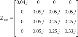
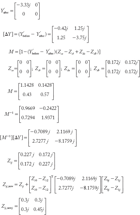
Obtain the bus impedance matrix of the power system network shown in Figure 3.12(a). Take reactance of each line as j0.3 p.u.
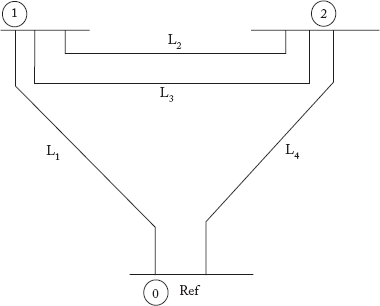
Fig 3.12(a) Power System Network for Example 3.6
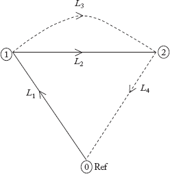
Fig 3.12(b) Graph for the Power System Network
Solution:
The graph for the network is given in Figure 3.12(b).
Step 1: Add branch L1 between buses 0 and 1, this Type-1 modification gives:
Step 2: Add branch L2 between buses 1 and 2, this Type-2 modification gives:

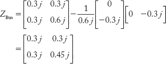
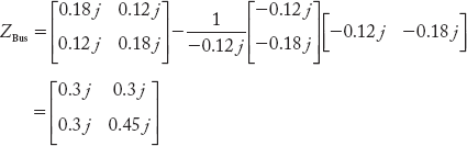
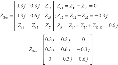
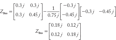
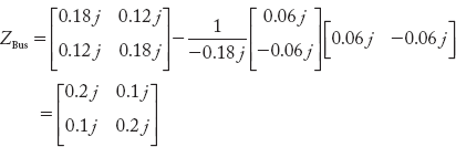
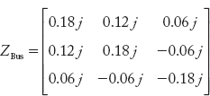
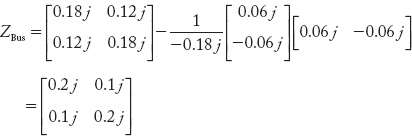
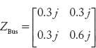
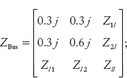
Step 3: Add link L3 between buses 1 and 2, this Type-4 modification gives:

where,

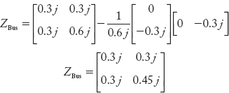
Now, the modified ZBus obtained by removing the fictitious bus l is:
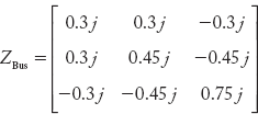
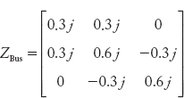
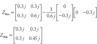
Step 4: Add link L4 between buses 0 and 2, a Type-3 modification gives:

Now, the modified ZBus obtained by removing the fictitious bus is:

MATLAB RESULTS
nw_data =
0 1.0000 0 0.3000
0 2.0000 0 0.3000
1.0000 2.0000 0 0.3000
1.0000 2.0000 0 0.3000
zbus =
0 + 0.1800i 0 + 0.1200i
0 + 0.1200i 0 + 0.1800i
Example 3.7
If the line L1 between the buses 0 and 1 is removed in Figure 3.12(a), modify the ZBus.
Solution:
If the line L1 in the figure is removed, the modified ZBus can be obtained by adding a link in parallel with the element such that impedance of the link added equals to the negative of the impedance of the element to be removed.
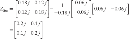
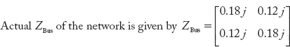
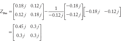
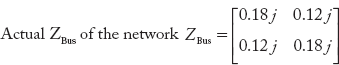
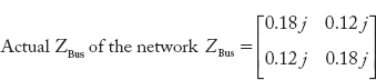
Actual ZBus of the network 
Add the link –j0.3 p. u between buses 0 and 1, a Type-3 modification gives:
Now, the modified ZBus obtained by removing the fictitious bus is:


Fig 3.12(c) Adding of a Link Element to Remove Branch
MATLAB RESULTS
nw_data =
0 1.0000 0 0.3000
0 2.0000 0 0.3000
1.0000 2.0000 0 0.3000
1.0000 2.0000 0 0.3000
0 1.0000 0 —0.3000
zbus =
0 + 0.4500i 0 + 0.3000i
0 + 0.3000i 0 + 0.3000i
Example 3.8
If the line L2 between the buses 1 and 2 is removed in Figure 3.12(a), modify the ZBus.
Solution:
If the line L2 in the figure is removed the modified ZBus can be obtained by adding a link in parallel with the element such that the impedance of the link added equals to the negative of the impedance of the element to be removed.
Actual ZBus of the network 
Add link –j0.3 p. u between 1 and 2, a Type-3 modification gives:
Now, the modified ZBus by removing the fictitious bus is:

MATLAB RESULTS
nw_data =
0 1.0000 0 0.3000
0 2.0000 0 0.3000
1.0000 2.0000 0 0.3000
1.0000 2.0000 0 0.3000
1.0000 2.0000 0 —0.3000
zbus =
0 + 0.2000i 0 + 0.1000i
0 + 0.1000i 0 + 0.2000i
Example 3.9
If the line L3 between the buses 1and 2 is removed in Figure 3.12(a), modify the ZBus.
Solution:
If the line L3 in the figure is removed, the modified ZBus can be obtained by adding a link in parallel with the element such that the impedance of the link added equals to the negative of the impedance of the element to be removed, as there is no mutual coupling between the elements. This is an example of removal of Type-4 modified element.
The actual Z-Bus of the network, 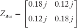
By adding link –j0.3 p. u between buses 1 and 2, we get

Now, the modified ZBus obtained by removing the fictitious bus is:
MATLAB RESULTS
nw_data =
0 1.0000 0 0.3000
0 2.0000 0 0.3000
1.0000 2.0000 0 0.3000
1.0000 2.0000 0 0.3000
1.0000 2.0000 0 —0.3000
zbus =
0 + 0.2000i 0 + 0.1000i
0 + 0.1000i 0 + 0.2000i
Example 3.10
If the line L4 between the buses 0 and 2 is removed in Figure 3.12(a), modify the ZBus.
Solution:
If the line L4 in the figure is removed, the modified ZBus can be obtained by adding a link in parallel with the element such that the impedance of the link added equals to the negative of the impedance of the element to be removed.
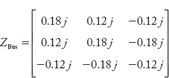
The actual Z-Bus of the network, 
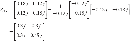
By adding link –j0.3 p. u between buses 0 and 2, we get
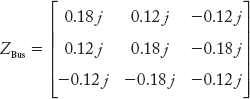
Now, the modified ZBus by removing the fictitious bus is:
MATLAB RESULTS
nw_data =
0 1.0000 0 0.3000
0 2.0000 0 0.3000
1.0000 2.0000 0 0.3000
1.0000 2.0000 0 0.3000
0 2.0000 0 — 0.3000
zbus =
0 + 0.3000i 0 + 0.3000i
0 + 0.3000i 0 + 0.4500i
3.5 Algorithm for the Formation of ZBus— CONSIDERATION OF MUTUALLY COUPLED ELEMENTS
In this section for the network changes we modify the bus impedance matrix by taking into account the mutual impedance.
3.5.1 Type-1 and Type-2 Modifications
In these cases, a new branch p-q is added as shown in Figure 3.13 to a partial (already assembled) network.
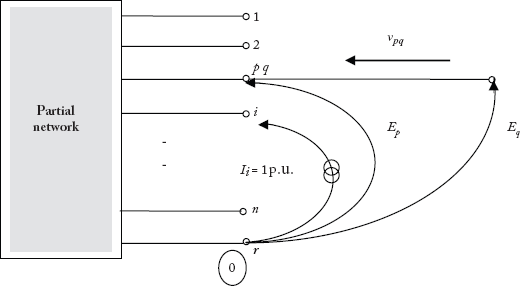
Fig 3.13 Addition of a Branch to a Partial Network
The performance equation for the modified network with the new branch p-q is

The network consists of bilateral passive elements, therefore Zqi = Ziq (q = 1, 2,…,n). Now we shall determine the elements of ZBus.
Determination of off-diagonal elements (Ziq):
The elements Ziq can be determined by injecting a current Ii = 1 p. u. at each ith bus except at the qth bus and calculating the voltage at the qth bus with respect to the reference node r as shown in Figure 3.13.
Since all other bus currents are zero except at ith bus, we can write:
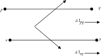
Assume that the element p-q is mutually coupled with a group of elements indicated by x-y. The currents in the elements of the network can be written in terms of primitive admittances and the voltages across the elements. Thus,
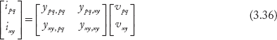
where,
ipq is the current through the added element.
vpq is the voltage across the added element.
ixy is the current through the already existing element in the partial network.
vxy is the voltage across of the already existing element xy.
ypq,pq is the self-admittance of the added element.
ypq,xy is the vector of mutual admittance between p-q and all other elements x-y with which it has mutual coupling.
From Figure 3.13,
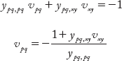
Further, from Equation (3.36)
The current in the added branch, ipq, is zero because the current source is connected between the bus i and the reference. However, the voltage vpq, across p-q, is not zero due to mutual coupling.
From Equation (3.38),

from the above,
Substituting Equation (3.39) in Equation (3.37),

By substituting Equation (3.35) in the above equation the off-diagonal elements are given by:
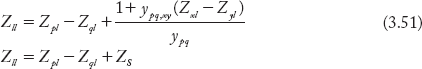
Determination of the diagonal element (Zqq):
To calculate Zqq, we inject Iq = 1 p. u. current and set all other bus currents as zeros (Ii = 0 p. u. for i = 1, 2,…, n).
It can be noted from Figure 3.13,
Now measure Eq with respect to reference. By using Equation (3.34) the bus voltages are:
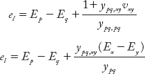
Substituting for ipq in Equation (3.38), we obtain
Substituting for vpq in Equation (3.37), we obtain

By substituting the Equation (3.41) in the above equation the diagonal element is given by:
3.5.2 Type-3 and Type-4 Modifications
Let the added element p-q be a link. A voltage source el is connected in series with the added element as shown in Figure 3.14. This creates a new fictitious node l which will be eliminated later. The value of el is such that the current through the fictitiously added branch element is zero i.e ipq = ipl = 0
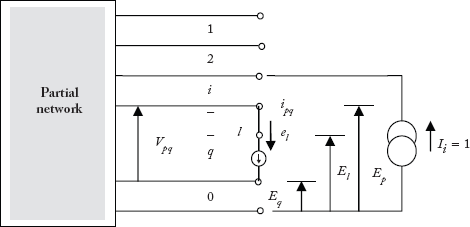
Fig 3.14 Addition of a Link to a Partial Network
The performance equation for the partial network with the added element p-l and the series voltage source el is:

Determination of off-diagonal elements:
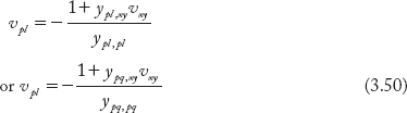
In the above equation E1, E2,…, En are measured voltages with respect to the reference bus. Where as El is the voltage of the lth bus with respect to bus q. Therefore,
The elements Zil, i fi l can be determined by injecting 1 p. u. current at the ith bus and setting all other bus currents as zeros and then calculating el with respect to the qth bus.
For Ii = 1 p. u., and for other bus currents zero in Equation (3.43), the bus voltages directly give impedance values as:
The voltage of the series source is:
From Equation (3.38) the ipl is:
Since ipq = ipl = 0
the value of vpl from the above equation is:
Taking ![]() the above equation can be written as:
the above equation can be written as:
Substituting Equation (3.47) in Equation (3.46),

Substituting Equation (3.45) in the above equation,
Determination of the diagonal element:
The value of Zll can be determined by injecting 1 p. u. current at the lth bus and then determining the voltage of bus l with respect to bus q.
For Il = 1 p. u., and for other bus currents zero in Equation (3.43), the bus voltages directly give impedance values as:
where, Ek (k = 1, 2,…, n) are the voltages with respect to the reference bus. The value of Zll can be found out directly by computing el. The current in the element p-l is
The current in terms of primitive admittances and voltages across the element are:
Since ypl,xy = ypq,xy and ypl,pl = ypq,p q, it follows that,
Substituting Equation (3.50) in Equation (3.46), we get
Substituting Equation (3.49) into the above equation,
Here, the summary of equations for formation of the bus impedance matrix is given as per the type modification defined earlier in Section 3.4.
3.5.3 Summary of Formulas
In this section, we summarize all types of modifications in ZBus.
Case-1: Mutually coupled elements are absent
For the case when mutually coupled elements are absent, the following relations are valid:

Substitution of above relations in Equations (3.40) and (3.42) yields:
Type-2 Modification
and
Type-1 Modification
If p is the reference bus, then EP = 0.
From Equation (3.35),
Therefore,

Type-4 Modification
From Equations (3.48) and (3.51),
and
Type-3 Modification
If p is the reference bus then,
and
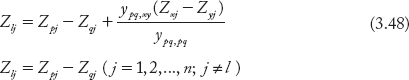
Elimination of lth row and lth column modifies the bus impedance matrix element as:
Case-2: Mutually coupled elements are present
The summary of formulas for this case is as given in the following table:
| Type Modification | Addition of an element to the network | Modified ZBus elements |
|---|---|---|
| Type-1 | A branch is added from a new bus q to the reference bus having mutual coupling with link between bus x and bus y |  |
| Type-2 | A branch is added from a new bus q to an old bus p having mutual coupling with link from bus x to bus y. | 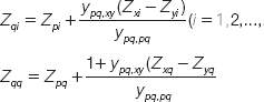 |
| Type-3 | A link is added from an old bus q to a reference bus having mutual coupling with link from bus x to bus y. | 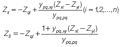
By eliminating fictitious bus l,
|
| Type-4 | A link is added from an old bus q to another old bus p having mutual coupling with link from bus x to bus y. | 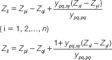
By eliminating fictitious bus l
|

3.6 Modifications In ZBus FOR CHANGES IN THE NETWORK
When the elements are added, the procedure presented in Section 3.5 can be used. In a power system, certain elements may have to be removed in situations such as tripping of generators, transformers and transmission lines. This section presents modifications in ZBus for the case when elements are removed or when the impedance value of an element is changed.
Case-1: Uncoupled Case
a) Procedure for removal of an element
If the element that has to be removed is not coupled to any other element, then the procedure for modifying ZBus is rather a simple one. The modified ZBus can be obtained by adding a link element in parallel with the element, such that its impedance value is negative and equal to the impedance value of the latter. This type of network changes is applicable to Type-3 and Type-4 modifications.
b) Impedance value of an uncoupled element is changed
If the impedance value of an element is changed, then the modified ZBus can be obtained by adding a link element in parallel to the element. The effective impedance of both the parallel elements should be equal to the desired impedance value of the element.
Case-2: Coupled Case
Modifying ZBus for the case when a mutually coupled element is to be removed or its impedance value has to be changed may be illustrated with the following derivation. Since the element is coupled with some other elements in the network, it is required to consider changes in the bus currents and voltages throughout the network.
The performance equations for the partial network are given by:
The ith bus voltage from the above equation is:
Upon removal of one element or due to change in the impedance value of a coupled element, the matrices of the network, equation (3.52) modifies to:
The ith bus voltage now changes to:
It is to be noted that, when a mutually coupled element is removed from the network, only those ZBus matrix elements corresponding to the element removed get affected, while the rest of the matrix elements remain the same. However, all bus voltages and currents change in the network, and in order to get the desired bus voltages in accordance to the said network changes, we provide suitable increments to the bus currents retaining the same ZBus.
Following the above discussion,
From the above, the ith bus voltage is:
where, ∆Ik change in the k th bus current.
Now, let a current source of 1 p. u. be connected at the jth bus and the other buses be kept open-circuited.
i.e., Ij = 1 p. u.
and
Suppose an element p-q which is to be removed (or its impedance value is to be changed) is mutually coupled to an element say x-y. Changes in the element currents are given by:
where, ∆Ik = ∆Ipq for k = p

and ∆Ik = 0 (for k = 1, 2,…, n; k ≠ j)
Substituting Equations (3.55) and (3.56) in Equation (3.54), we obtain the ith bus voltage as:

Let the group of subscripts p-q and x-y be denoted as a and b, as shown:
By substituting the above-defined subscripts into Equation (3.57), its condensed form is:
In view of the primitive admittance matrix, the performance equation (3.58) can be written as:
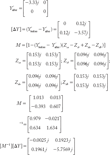
Y'before is primitive admittance matrix before removing the element
Y'after is primitive admittance matrix after removing the element
The subscripts of (Y'before — Y'after) are cd.
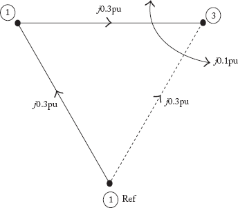
Fig 3.15 Example for Formation of Y'before and Y'after
Formation of primitive impedance matrices before and after removal of elements
Consider the power system graph shown in Figure (3.15). Self and mutual reactances are marked in the figure.
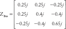
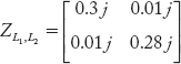
The primitive impedance matrix before elimination of element between buses 1–3 is:

The primitive impedance matrix before elimination of element between buses 1–3 is:
The voltage vector in the Equation (3.59) is:
Using Equation (3.58),
Substituting Equations (3.60) and (3.61) in Equation (3.59), we get
Rearranging the terms in the above equation, we obtain
On simplification of the above,
where,![]()
Substituting Equation (3.62) in Equation (3.58), we get
From the above equation the elements of the impedance matrix can be obtained as:
The following numerical problems explain all the modifications in ZBus. They consider the mutual effect and removal. Answers to the problems can be verified by executing the MATLAB program.
MATLAB Program for the formation of ZBus when mutual coupling of elements is considered.
% The student can use this program for forming ZBus when the elements have
% mutual coupling with other elements
%This program is developed by Dr. N. V. RAMANA
fprintf(‘Take reference bus 0 always ')
elements=input(‘enter number of elements='),
zdata=zeros(elements,6);
fprintf(‘enter data in this format: 1.Element no. 2.From bus no. 3.To bus no. 4.Self impedance ')
fprintf(‘5.Mutually coupled to element no 6. Mutual Impedance Value ')
fprintf(‘if element has no mutual coupling enter Item 6 as zero ')
fprintf(‘when the program ask for “zdata”, enter like the following example: ')
fprintf(‘Zdata= [1 0 2 0.25j 2 0.01j; 2 0 1 0.2j 1 0.01j; 3 1 3 0.25j 0 0;4 1 2 0.3j 0 0; = 2 3 0.1j 0 0]; ')
yprimitive=zeros(elements,elements);
zprimitive=zeros(elements,elements);
zdata=input(‘enter Zdata='),
%formation of primitive impedence matrix
x=zdata(:,5);
for i=1:elements
zprimitive(i,i)=zdata(i,4);
if x(i)~=0
zprimitive(x(i),i)=zdata(i,6);
end
end
yprimitive=inv(zprimitive);
%formation of bus incidence matrix A begins
nb=max(max(zdata(:,2)),max(zdata(:,3)));
%initialize A matrix
nbuses=nb—1;
A=zeros(elements,nbuses); % gives size of matrix A and is initialized to zero
for i=1:1:elements,
if zdata(i,2)~=0 % formation of matrix A
A(i,zdata(i,2)) =1;
end % end for ‘if’ statement
if zdata(i,3)~ =0
A(i,zdata(i,3)) = –1;
end % end for ‘if’ statement
end
ybus=A'*yprimitive*A;
zbus=inv(ybus)
Example 3.11
A 3-bus power system network is shown in Figure 3.16(a). Obtain the bus impedance matrix by using building algorithm. Take bus (1) as reference. The self and mutual reactances are indicated in the figure.
Solution:
The graph of the power system is shown in Figure 3.16(b). Consider 1–2, 2–3 as branches and 1–3 as a link.
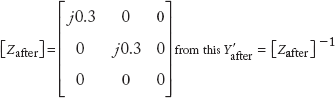
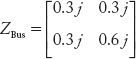
Step 1: Add branch 1–2, a Type-1 modification gives

Fig 3.16(a) Power System for Example 3.11
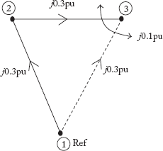
Fig 3.16(b) Graph of the Power System for Example 3.11
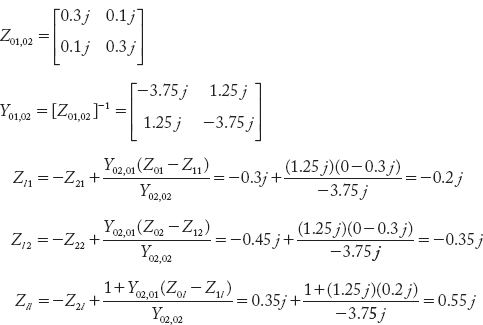
Step 2: Add branch 2–3, a Type-2 modification gives
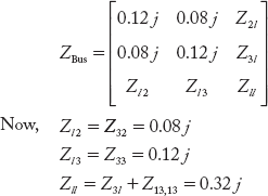
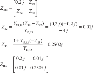
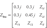
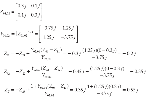
Step 3: Add link 1–3, which is mutually coupled with link 2–3. This is a Type-3 modification.
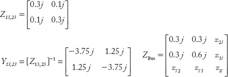
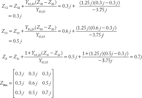
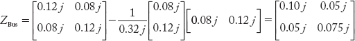
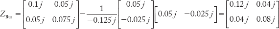
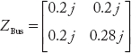
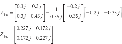
The modified Z-bus obtained by removing fictitious bus is:

MATLAB RESULTS
>> zbus_mutual_nvr
Take reference bus 0 always
Enter number of elements=3
Enter Zdata=[1 0 1 0.3j 0 0; 2 1 2 0.3j 3 0.1j; 3 0 2 0.3j 2 0.1j]
zbus =
0 + 0.1714i 0 + 0.0857i
0 + 0.0857i 0 + 0.2429i
Example 3.12
For the power system in Example 3.11,
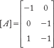
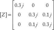
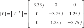
(a) Obtain the bus incidence matrix [A], (b) Primitive impedance matrix[z], (c) Primitive admittance matrix [y] = [z–1], (d) YBusby singular transformation method, (e) Obtain ZBus by taking the inverse of ZBus.
Compare the zBus with the result of Example 3.11.
Solution:
With reference to the graph in Figure 3.16(b),
- Bus impedance matrix
- Primitive impedance matrix
- Primitive admittance matrix
-

-

ZBus obtained in both the examples is same.
Example 3.13
Obtain the bus impedance matrix for the power system network shown in Figure 3.17(a) by the step-by-step method. The self and mutual reactances indicated in the figure are per unit values.
Solution:
The graph for the power system is shown in Figure 3.17(b). Consider the elements 1—3, 1—2 and 2—4 as branches and others as links.
Step 1: Add branch 1—2, this Type-1 modification gives:
Step 2: Add branch 1–3, which is mutually coupled with 1–2. This is also a Type-1 modification.

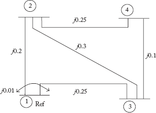
Fig 3.17(a) Power System for Example 3.13
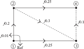
Fig 3.17(b) Graph of the Power System of Example 3.13
Step 3: Add link 2–3, this is Type-4 modification.

Now, the modified Z-Bus by eliminating the fictitious bus,

Step 4: Add branch 2–4, this is Type-2 modification.
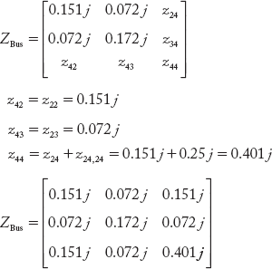
Step 5: Add link 4–3, this is Type-4 modification.
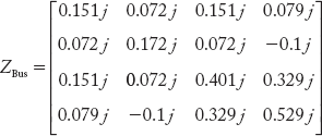
Now, the modified Z-Bus is given by
MATLAB Program Results
>> zbus_mutual_nvr
Take reference bus 0 always
Enter number of elements=5
Enter data in this format: 1. Element no. 2.From bus no. 3. To bus no. 4. Self impedance 5. Mutually coupled to element no. 6. Mutual Impedance Value
If element has no mutual coupling enter Item 6 as zero
When the program ask for “zdata”, enter like the following example:
Zdata=[1 0 2 0.25j 2 0.01j; 2 0 1 0.2j 1 0.01j; 3 1 3 0.25j 0 0;4 1 2 0.3j 0 0; = 2 3 0.1j 0 0];
Enter Zdata=[1 0 2 0.25j 2 0.01j; 2 0 1 0.2j 1 0.01j; 3 1 3 0.25j 0 0;4 1 2 0.3j 0 0; = 2 3 0.1j 0 0];
zbus =
0 + 0.1390i 0 + 0.0871i 0 + 0.1019i
0 + 0.0871i 0 + 0.1526i 0 + 0.1339i
0 + 0.1019i 0 + 0.1339i 0 + 0.1962i
>>
Example 3.14
Obtain the ZBus of the power system network shown in Figure 3.18(a) by using building algorithm. The self and mutual reactances are indicated in the figure. Take Bus (1) as reference.
Solution:
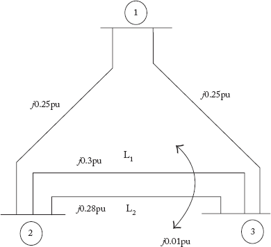
Fig 3.18(a) Power System for Example 3.14
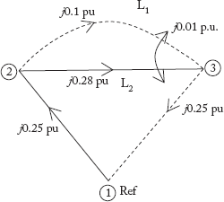
Fig 3.18(b) Graph of the Power System for Example 3.14
Consider the graph in Figure 3.18(b).
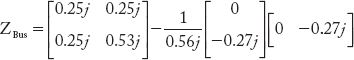
Step 1: Add branch 1–2, this is a Type-1 modification.
Step 2: Add branch L2, this is a Type-2 modification.

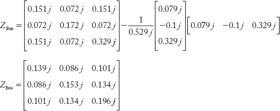
Step 3: Add the link L1, which is mutually coupled with L2. This is a Type-4 modification. The primitive impedance and admittance matrices are:

The augmented impedance matrix is:

Now, the modified ZBus is given by eliminating the fictitious bus,
Step 4: Add link 1– 3, this is a Type-3 modification.
Now, the modified ZBus is given by eliminating the fictitious bus,

MATLAB Program Results
>> zbus_mutual_nvr
Take reference bus 0 always
Enter number of elements = 4
Enter Zdata = [1 0 1 0.25j 0 0; 2 2 1 0.28j 3 0.01j; 3 1 2 0.3j 0 0.01j;4 0 2 0.25j 0 0];
zbus =
0 + 0.1527i 0 + 0.0973i
0 + 0.0973i 0 + 0.1527i
>>
Example 3.15
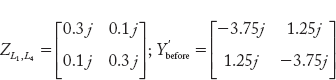
In the power system network shown in Figure 3.18(a), the line L2 is removed between buses 2 and 3. Obtain the modified ZBus matrix.
Solution:
Removal of network element L2, which is mutually coupled to L1 can be obtained as:
where, the indices a = 2; b = 3; c = 2; d = 3;
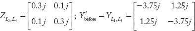
The primitive impedance and admittance matrices before elimination are:

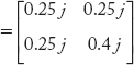
The modified primitive admittance sub-matrix after elimination of element is:
Before elimination 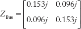
After elimination of element

Example 3.16
For the graph of a power system network shown in Figure 3.19. Obtain the Z-Bus matrix by building algorithm. The self reactance of each element is j0.2 p. u. Branch elements are shown as dark lines and link elements as dotted lines. Take mutual reactance as j0.01 p. u.
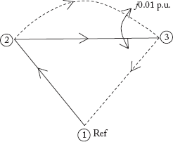
Fig 3.19 Graph of the Power System for Example 3.16
Solution:
In the figure take the branch between 2 and 3 as L1 and link as L2.
Step 1: Add branch 1–2, this is Type-1 modification.
Step 2: Add branch L1, this is Type-2 modification.
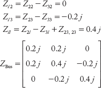
Step 3: Add link L2, which is mutually coupled with L1. This is a Type-4 modification.


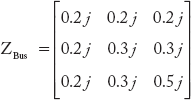
Step 4: Add link 1–3, this is a Type-3 modification.
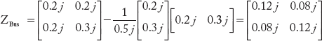
Now, the modified ZBus is given by
Matlab results
zbus_mutual_nvr
Take reference bus 0 always
Enter number of elements=4
Enter Zdata=[1 0 1 .2j 0 0;2 1 2 .2j 3 0.01j;3 1 2 .2j 2 .01j;4 0 2 0.2j 0 0]
zbus =
0 + 0.1208i 0 + 0.0792i
0 + 0.0792i 0 + 0.1208i
Example 3.17
If one of the lines in Figure 3.18 is removed, modify the ZBus matrix.
Solution:
Let the line 1–3 in Figure 3.18 be removed. For this we should add a link across 1 and 3 such that its value is —j0.2 p. u.
Now add the new link across 1 and 3. This is Type-3 modification.
The modified ZBus is given by

Example 3.18
Let the lines L1 and L4 be mutually coupled to each other with reactance j0.1 p. u. Obtain ZBus using the building algorithm.
Solution:
The graph of the power system is shown in Figure 3.20.
Step 1: Add branch L1 between 0 and 1, This is Type-1 modification.
Step 2: Add branch L2 between 1 and 2, this is a Type-2 modification.
Step 3: Add link L3 between 1 and 2, this is a Type-4 modification.
Now, the modified Zbus is given by
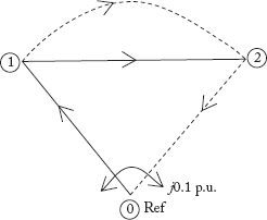
Fig 3.20 Graph of the Power System in Example 3.18

Step 4: Add link L4 between 0 and 2, which is mutually coupled with L1. This is a Type-3 modification.
The primitive impedance matrix is,
Now, the modified Zbus is given by

Matlab results
>> zbus_mutual_nvr
Take reference bus 0 always
Enter number of elements=4
Enter Zdata= [1 0 1 0.3j 4 0.1j; 2 2 1 0.3j 0 0; 3 1 2 0.3j 0 0;4 0 2 0.3j 1 0.1j];
zbus =
0 + 0.2273i 0 + 0.1727i
0 + 0.1727i 0 + 0.2273i
>>
Example 3.19
In Figure 3.20, if the element L4 is removed, find the modified ZBus.
Solution:
Removal of network element L4, which is mutually coupled to L1, is obtained from
Where the indices a = 0; b = 2; c = 0; d = 1.
The primitive impedance matrix is
The modified primitive admittance sub-matrix is
Example 3.20
Obtain the bus impedance matrix of the power system network shown in Figure 3.21(a). Take reactance of each line as j0.3 p. u.
Solution:
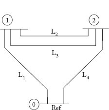
Fig 3.21(a) Power System for Example 3.20
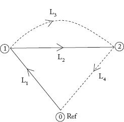
Fig 3.21(b) Graph of the Power System for Example 3.20
The graph for the network is given in Figure 3.21(b)
Step 1: Add branch L1 between 0 and 1. This is Type-1 modification.
Step 2: Add branch L2 between 1 and 2. This is Type-2 modification.

Add link L3 between 1and 2. This is Type-4 modification.
Now, the modified Zbus is given by eliminating the fictitious bus l
Step 4: Add link L4 between 0 and 2. This is Type-3 modification.
Now, the modified Z-bus is given by eliminating the fictitious bus l
Matlab results
zbus_mutual_nvr
Take reference bus 0 always
Enter number of elements=4
Enter Zdata=[1 0 1 .3j 0 0;2 1 2 .3j 0 0;3 1 2 .3j 0 0;4 0 2 .3j 0 0];
zbus =
0 + 0.1800i 0 + 0.1200i
0 + 0.1200i 0 + 0.1800i
Example 3.21
If the line L1 between the buses 0 and 1 is removed from Figure 3.21(a), modify the ZBus.
Solution:
If the line L1 in Figure 3.20 is removed, the modified ZBus can be obtained by adding a link in parallel with the element such that the impedance of the link added equals to the negative of the impedance of the element to be removed, as there is no mutual coupling between the elements. This is the removal of a Type-1 modified element.
By adding the link — j0.3 p. u between 0 and 1, we get


Figure 3.21(c) Graph of the Power System for Example 3.20 with L1 removed
Now, the modified Z-bus is given by:
Example 3.22
If the line L2 between the buses 1 and 2 is removed from Figure 3.21(a), modify the ZBus.
Solution:
If the line L2 in the figure is removed, the modified Z Bus can be obtained by adding a link in parallel with the element such that the impedance of the link added equals to the negative of the impedance of the element to be removed, as there is no mutual coupling between the elements. This is the removal of a Type-2 modified element.

By adding link —j0.3 p. u. between 1 and 2, we get:
Now, the modified ZBus is given by eliminating the fictitious bus l,
Example 3.23
If the line L3 between the buses 1 and 2 is removed from Figure 3.21(a), modify the ZBus.
Solution:
If the line L3 in the figure is removed, the modified Z-Bus can be obtained by adding a link in parallel with the element such that impedance of the link added equals to the negative of the impedance of the element to be removed, as there is no mutual coupling between the elements. This is the removal of a Type-4 modified element.
By adding link —j0.3 p. u. between 1 and 2, we get
Now, the modified ZBus is given by eliminating the fictitious bus l
Example 3.23
If the line L4 between the buses 0 and 2 is removed from Figure 3.21(a), modify the ZBus.
Solution:
If the line L4 in the figure is removed, the modified ZBus can be obtained by adding a link in parallel with the element such that impedance of the link added equals to the negative of the impedance of the element to be removed, as there is no mutual coupling between the elements. This is the removal of a Type-3 modified element.
By adding link —j0.3 p. u. between 0 and 2, we get
Now, the modified ZBus is given by eliminating the fictitious bus l
Example 3.24
Let the lines L1 and L4 be mutually coupled to each other with reactance j0.1 p. u. Obtain the ZBus.
Solution:
The graph is given in Figure 3.21(d).
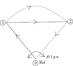
Fig 3.21(d) Consideration of Mutual Coupling
Step 1: Add branch L1 between 0 and 1. This is Type-1 modification.
Step 2: Add branch L2 between 1 and 2. This is Type-2 modification.
Step 3: Add link L3 between 1 and 2. This is Type-4 modification. The augmented impedance matrix is:
where,

The augmented impedance matrix with fictitious bus l,
Now, the modified ZBus given by eliminating fictitious bus l is:
Step 4: Add link L4 between 0 and 2, which is mutually coupled with L1. This is a Type-3 modification.
The primitive impedance matrix is,
Now, the modified ZBus is given by eliminating the fictitious bus l
Matlab results
>> zbus_mutual_nvr
Take reference bus 0 always
Enter number of elements=4
Enter Zdata= [1 0 1 0.3j 4 0.1j; 2 2 1 0.3j 0 0; 3 1 2 0.3j 0 0;4 0 2 0.3j 1 0.1j];
zbus=
0 + 0.2273i 0 + 0.1727i
0 + 0.1727i 0 + 0.2273i
>>
Example 3.25
In Figure 3.21(a), if the element L4 is removed, find the ZBus from the ZBus obtained in Example 3.24.
Solution:
Removal of network element L4, which is mutually coupled to L1, is obtained from
Where the indices are a = 0, b = 2, c = 0, d = 1.
The primitive impedance matrix corresponding to the element to be removed is:
The modified primitive admittance sub-matrix is,

where,

Questions from Previous Question Papers
- Give the applications of the ZBus building algorithm.
- For a partial n-bus power system ZBus is available. An element needs to be added to the existing network. Now describe how the step-by-step procedure shall modify the ZBus for Type-1 modification. Neglect mutual effect.
- For a partial n-bus power system ZBus is available. An element needs to be added to the existing network. Now describe how the step-by-step procedure shall modify the ZBus for Type-2 modification. Neglect mutual effect.
- For a partial n-bus power system ZBus is available. An element needs to be added to the existing network. Now describe how the step-by-step procedure shall modify the ZBus for Type-3 modification. Neglect mutual effect.
- For a partial n-bus power system ZBus is available. An element needs to be added to the existing network. Now describe how the step-by-step procedure shall modify the ZBus for Type-4 modification. Neglect mutual effect.
- For a partial n-bus power system ZBus is available. An element needs to be added to the existing network. Now describe how the step-by-step procedure shall modify the ZBus for Type-1 modification. Consider the mutual effect.
- For a partial n-bus power system ZBus is available. An element needs to be added to the existing network. Now describe how the step-by-step procedure shall modify the ZBus for Type-2 modification. Consider the mutual effect.
- For a partial n-bus power system ZBus is available. An element needs to be added to the existing network. Now describe how the step-by-step procedure shall modify the ZBus for Type-3 modification. Consider the mutual effect.
- For a partial n-bus power system ZBus is available. An element needs to be added to the existing network. Now describe how the step-by-step procedure shall modify the ZBus for Type-4 modification. Consider the mutual effect.
- Explain how an element can be deleted or how its impedance value can be changed. Neglect Mutual effect.
- Explain how an element can be deleted or how its impedance value can be changed. Consider the mutual effect of elements.
- Build the ZBus for a power system whose element data is given in the following table.
Element No. Connected Between Bus Nos. Self Reactance in P. U. 1 1–2 0.3 2 1–3 0.4 3 2–3 0.5 - Modify the ZBus that is obtained in Q. 3.12, if a line is added between buses 1 and 3 with a self-reactance value of j0.5 p. u.
- Modify the ZBus that is obtained in Q. 3.12, if a line is added between buses 1 and 3 with a self-reactance value of j0.5 p. u. reactance and a mutual reactance of j0.01 p.u.
- Explain what do you mean by a partial network.
- Explain representation of an element in admittance form and impedance form.
- Describe the algorithm for formation of bus impedance matrix for addition of a branch.
- Describe the algorithm for formation of bus impedance matrix for addition of a link.
- Derive an expression for addition of a link to a network with mutual inductance.
- Derive an expression for adding a branch element between two buses in the Zbus building algorithm with mutual inductance.
- Explain the modifications necessary in the ZBus when a mutually coupled element is removed or its impedance is changed.
- What the advantages of ZBus building algorithm? Explain what is primitive network, primitive admittance and impedance matrix. Explain by giving an example.
- Consider the graph of a power system network shown in Figure Q1.
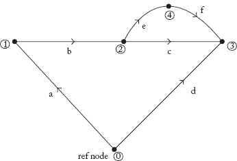
Fig Q1
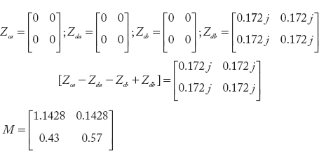
Per unit impedance values of various elements are:
Xa = j1.25; Xb = j0.25; Xc = j0.4; Xd = j1.25; Xe = j0.125; Xf = j0.2
Determine the bus impedance matrix for the network connecting above impedances.
- Describe the procedure of modifications in the existing Zbus by adding mutually coupled branch from existing buses (P) and (K).
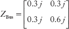
- Obtain the bus impedance matrix by the step-by-step method. A three-bus system having reference node (4), has line impedances in per unit as shown in Figure Q2.

Fig Q2
Competitive Examination Questions
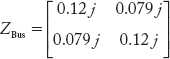
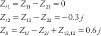
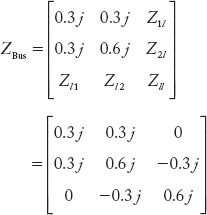
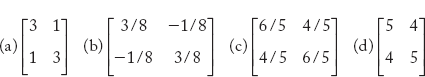
- The bus numbers and impedances are marked. The bus impedance matrix of this network is
[IES 1996 Q NO: 106]
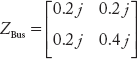
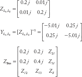
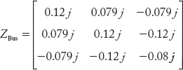
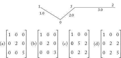
- A power system network consists of three elements 0—1, 1—2 and 2—0 of p.u. impedances 0.2, 0.4 and 0.4 respectively. Its bus impedance matrix is given by
[IES 1997 Q NO: 42]
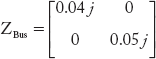
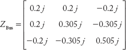
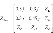
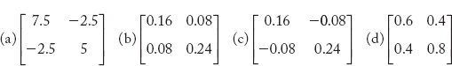
- With the usual notation, impedance matrix for the system shown in the accompanying figure is

[IES 1999 Q NO: 60]
- The bus admittance matrix of a power system is as shown below. The impedance of the line between buses 2 and 3 will be

- j0.1
- —j0.1
- j0.2
- —j0.2
[IES 2003 Q NO: 30]
- Normally ZBus matrix is a
- Null matrix
- Sparse matrix
- Full matrix
- Unity matrix
[IES 2004 Q NO: 111]
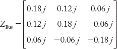
- The bus impedance matrix of a 4-bus power system is given by
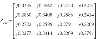
A branch having an impedance of j0.2Ω is connected between bus 2 and the reference. Then the values of Z22,new and Z23,new of the bus impedance matrix of the modified network are respectively.
- j 0.5408 Ω and j 0.4586 Ω
- j 0.1260 Ω and j 0.0956 Ω
- j 0.5408 Ω and j 0.0956 Ω
- j 0.1260 Ω and j 0.1630 Ω
[GATE 2003 Q.No. 11]