CHAPTER 7
Short-Circuit Analysis—2 (Unbalanced Fault Analysis)
7.1 Introduction
If the fault involves only one or two of the three possible phases, then the fault is said to be an unbalanced or asymmetrical fault. Due to these faults, the system loses symmetry or balanced condition. Fault calculations can be easily performed by the use of a tool known as the “symmetrical component”. Using these components unbalanced vectors can be transformed into balanced vectors, through which calculations can be performed on a single-phase basis. This makes calculations easier as seen in the case of symmetrical fault analysis.
7.2 Symmetrical Components
In the year 1918, French mathematician Fortescue proposed a mathematical tool known as “symmetrical components”. According to this, a set of n-unbalanced vectors can be resolved into n sets of balanced vectors, with each set comprising of n-balanced vectors. For example, a set of 3-unbalanced vectors IR, IY and IB can be transformed into three sets of balanced vectors, with each set containing 3-balanced vectors.
As our interest is in 3-phase, let us transform the three unbalanced vectors into three sets of balanced vectors. These three sets are:
- Positive sequence set
- Negative sequence set
- Zero sequence set
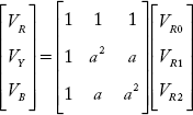
In terms of balanced sequence components, the unbalanced vectors can be written as follows:
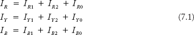
Equation (7.1) can be written in the matrix form as:
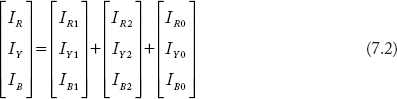
In Equation (7.2) the matrix on the left hand side represents the three-phase unbalanced currents. On the right hand side, the first matrix corresponds to the positive sequence set, the second matrix corresponds to negative sequence components and the last, third matrix represents zero sequence in the three-phase system RYB. Suffix 1, 2 and 0 are assigned respectively to positive, negative and zero sequence components. The description of sequence components is as follows:
1) Positive sequence components
IR1, IY1 and IB1 corresponding to the respective unbalanced vectors IR, IY and IB are the balanced vectors having the same magnitude but displaced 120° apart. These components have the sequence of RYB of the original unbalanced vectors and are shown in Figure 7.1
2) Negative sequence components
IR2, IY2 and IB2 corresponding to the unbalanced vectors IR, IY and IB respectively are the balanced vectors having equal magnitudes, but displaced 120° apart. These components have the sequence exactly opposite to that of original unbalanced vectors. These components are shown in Figure 7.2.
In order to obtain the opposite sequence, the negative sequence components are rotated in the clockwise direction, in contrast to the conventional anticlockwise direction. This is shown in Figure 7.2(b): RBY, BYR and YRB are the negative sequences. The same negative sequence can be obtained when the vectors are rotated in the anticlockwise direction as shown in Figure 7.2(c), with the positions depicted differently.

Fig 7.1 (a) Original Unbalanced Vectors, (b) Positive Sequence Components
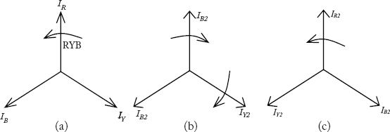
Fig 7.2 (a) Original Vectors, (b) Negative Sequence Components (Cw Direction), (cz) Negative Sequence Components (Acw Direction)
3) Zero sequence components
These components have no (zero) sequence. These components are equal in magnitude and are in phase with each other as shown in Figure 7.3.
In addition to the currents discussed earlier, voltages and powers are can also be transformed into sequence components.
7.2.1 Operator a
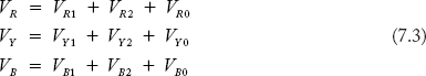
Operator ‘a’ is defined as a unit vector with magnitude equal to 1 and angle 120° and is given as:
When a vector is multiplied by the operator ‘a’, the vector shifts to 120° in the anticlockwise direction without the magnitude being changed. Similarly, when it is multiplied by a2, it shifts to 240° in the anticlockwise direction.
Some important relations with operator a:
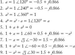

Fig 7.3 Zero Sequence Components
7.2.2 Sequence Components in Terms of Operator a
As sequence components have the same magnitude, the Y- and B-phase sequence components can be written in terms of R-phase.
Referring to Figure 7.1(b), and by taking IR1 as reference:
Referring to Figure 7.2(c) and by taking IR2 as reference:

As zero sequence components have no phase difference,
Rewriting Equation (7.1) and substituting the above relations,
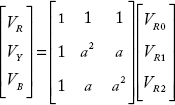
Equation (7.4) may be represented in the matrix form as

Equation (7.5) may be rewritten with the operator A matrix.
where A is the operator A matrix. Similarly the voltages can be written as:
Note: For the given digital vectors, the sequence components can be obtained as:

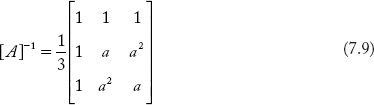
where the inverse of the operator matrix [A] is
Example 7.1
Let the three-phase currents be ![]() Determine the sequence components. Assume the sequence is RYB.
Determine the sequence components. Assume the sequence is RYB.
Solution:

The three phase currents are balanced. Using Equation (7.8b)

Using relations on operator a,
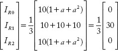
From the above,
Note: The above numerical example illustrates that in the balanced system only positive sequence currents are present.
Example 7.2
Let the three-phase currents be ![]() The phase sequence is RYB. Find the sequence components.
The phase sequence is RYB. Find the sequence components.
Solution:
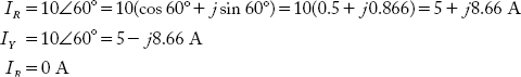
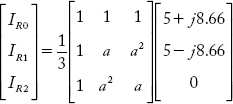
On simplification,
Example 7.3
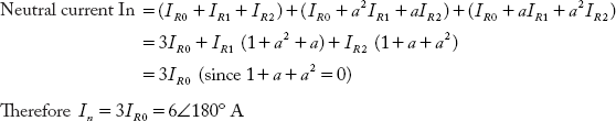
Determine the neutral current in the star, neutral grounded system from the given symmetrical components ![]()
Solution:
7.3 Sequence Impedances
The impedance offered by the circuit component to the flow of positive sequence current is known as positive sequence impedance. Similarly, the negative and zero sequence impedances can be defined.
7.3.1 Sequence Impedances of Individual Components
A summary of the experimental results of sequence impedances is presented below.
a) Generator
Positive sequence impedance
Z1 = jX″d (if the sub-transient state of fault is of interest)
= jX′ d (if the transient state fault is of interest)
= jXd (if the steady-state value of fault is of interest)
Negative sequence impedance
The negative sequence impedance offered by the generator is generally written as:
The zero sequence impedance of the generator is usually much smaller than Z1 and Z2 of values. Let Zg0 is be the zero sequence impedance of the generator. Then, the numerical values of the generator follow the relation:
b) Transformer and Transmission line
These two are said to be static devices. Since phase sequence has no effect on their operation, positive and negative sequence impedance and negative impedance are exactly be the same. For these devices, the relation between the sequence impedances is given as:
Example 7.4
Consider a fully transposed 3-phase transmission line, having self reactance of Xs and Xm.
Solution:
Consider the transposed transmission as shown in Figure 7.4
Let Xs = Self reactance of each line
Xm = Mutual reactance between any two lines

Fig 7.4 Power System Network of Example 7.4
Voltage drop across each line is due to self and mutual reactance and is given by:
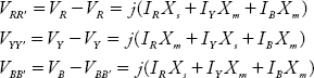
In the matrix form, the above equations can be written as:
the voltage drop and current in terms of sequence components can be written as
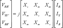
The voltage drop of sequence components can be obtained by multiplying sequence currents with sequence impedances. Therefore, from the above equations the sequence impedance matrix is:

On simplification of the above equation, the sequence impedance can be obtained as
where is
Note: Sequence impedance and sequence network are mutually disjoint as evident from the observation that the off-diagonal terms are zeros in Equation (7.10).
7.3.1 Summary of Sequence Components
- Three-phase unbalanced currents and voltages can be transformed into three sets of symmetrical components, namely, the positive, negative and zero sequence components.
- Symmetrical component theory is a tool to tackle unbalance fault analysis and its use is justified more analytically than physically.
- It may be understood that positive sequence such as currents and voltages are the original vectors while the other two sequence components are fictitious.
- In a balanced system, only positive sequence components are present (refer Example 7.1).
- The zero sequence currents in an unbalanced system is equal to one-third of total current in the neutral (I0 = IN /3).
- The positive, negative and zero sequence networks are mutually disjoint (refer Ex: 7.4) and can be handled separately.
7.4 Sequence Networks
A single-phase per-unit equivalent reactance network is sufficient to couple three-phase fault analysis. This makes three-phase fault analysis simple and easier. The question of present interest is:
Can we complete unbalanced fault analysis on a single-phase basis?
The answer to this question is yes because of the use of symmetrical components in unbalanced fault analysis. The method of performing unbalanced fault analysis on a single-phase basis is presented below.
Consider the unbalanced current described by Equation (7.5)

The equation explains that unbalanced currents can be determined, once the three sequence currents are known. The three sequences IR0, IR1, IR2 are the components of R-phase currents IR. IR1 can be obtained through the positive sequence network containing positive sequence component voltages and impedance. In a similar manner the negative and zero sequence currents can also be obtained through negative and zero sequence networks. These three networks are mutually disjoint. Hence, we need to convert the given single-line diagram of the power system into three mutually disjoint sequence networks for the purpose of determining the three sequence currents. Once the sequence currents are known, the fault analysis may be concluded. The following section describes the method of converting the single-line representation of a power system into three-sequence networks.
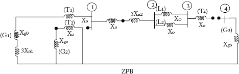
Consider the single-line diagram shown in Figure 7.5
Figure 7.1 shows a generator, transformer and transmission line. We need to convert this into three-sequence networks. We deal this problem by understanding the procedure of representing generator, transformer and transmission line individually in the three- sequence networks. Once the procedure for individual components is known, the sequence network can be easily obtained by integrating the individual elements.
7.4.1 Generator Representation in Three-Sequence Networks.
Let the generator sequence impedances be known values. Zg1, Zg2 and Zg0 are the positive, negative and zero sequence impedances of the generator. In fault analysis, the generator is represented as a constant voltage source behind the reactance. As a first step the generator placed in positive, negative and zero sequence networks is represented in a similar manner as shown in Figure 7.6.
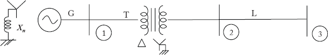
Fig 7.5 Single-Line Diagram of a Single-Power System Network
In Figure 7.6, E is the internal emf produced by the generator. The sequence currents, impedances and voltages are also indicated in the figure. In the second step, we verify two aspects:
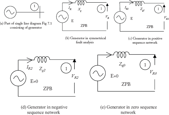
Fig 7.6 Generator Representation in Three-Sequence Networks
- Can the generator be shown as voltage source in all sequence networks?
- The star-connected generator winding neutral may be grounded or ungrounded. Does it have any effect on generator representation?
Verification of the above aspects results in modification of the generator representation in the three-sequence networks.
For a given direction of rotation of the rotor, the generator sets up emfs in the three phases with a phase sequence of RYB. As the positive sequence of voltages is also RYB, there is no problem for the generator to produce positive sequence voltages. Hence, the generator can be represented as a voltage source in the positive sequence network. To produce negative sequence voltages, the generator rotor has to rotate in the opposite direction.
A single rotor cannot rotate simultaneously in both the directions. Thus, a generator cannot generate negative sequence voltages. Hence it should not be shown as a voltage source in the negative sequence network. Finally, when the rotor starts rotating, it sets up a sequence. The zero-sequence voltages have no sequence. Therefore, the generator should generate zero-sequence voltages under still condition of the rotor. As this is not possible, it can be concluded that the generator should not be shown as a voltage source in a zero-sequence network.
Discussion on the effect of neutral grounding in generator representation
The following discussion is also valid for negative sequence network.
Let the generator neutral current In be resolved into components as: In = In1 + In2 + In0 where In1, In2 and In0 are the sum of positive, negative and zero sequence current components of R, Y and B phases as:


Fig 7.7 Generator Neutral Condition in the Positive Sequence Network
In Figure 7.3, the algebraic sum of currents leaving junction N is IR1 + IY1 + IB1, which is always zero. Since positive sequence currents are balanced and have a 120° phase shift,
Let the switch S in Figure 7.3 be open. That is, the generator neutral is ungrounded. For this condition, the current entering into junction N (i.e. In1) is zero and Kirchhoff's current law (KCL) is satisfied. Hence, there is no problem for the flow of positive sequence currents when the neutral is in open condition. Now, when the neutral is solidly grounded a current of In1 can flow through it. But as In1 = IR1 + IY1 + IB1 = 0, the sum of incoming currents is zero and KCL is satisfied. However, if the neutral is reactance grounded with Zn, the value of In1 cannot be limited to zero current. It can therefore be concluded that neutral grounding has no effect on the representation of a generator in positive and negative sequence networks, and that the condition of the neutral need not be verified.
Zero sequence Network
Let the generator neutral be ungrounded. Referring to Figure 7.8(a), the incoming current into junction N is zero, whereas the algebraic sum of outgoing currents is IR0 + IY0 + IB0 = 3 × IR0. In this ground neutral condition, KCL is not satisfied and therefore such currents do not exist. This effect can be represented as an open circuit between neutral (ZPB) and junction N as shown in Figure 7.8(b).

Fig 7.8(a) Generator Neutral Condition in the Zero-Sequence Network
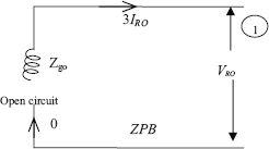
Fig 7.8(b) Neutral Ungrounded Condition of the Generator
Next, let the generator neutral be grounded through an impedance Zn. In this condition, the circuit is closed, and incoming current to junction N can flow through it. The value of incoming current is Ino = 3IR0, and as the sum of outgoing current is also equal to 3IR0, KCL is satisfied. Therefore such currents do exist.
Due to flow of 3IR0 current into neutral, a voltage drop of 3IR0 Zn takes place. This raises the potential of neutral from zero to 3IR0 Zn. Now the zero potential point (ZPB) shifts down from neutral to the ground. Referring to Figure 7.8(b), the total voltage drop from ZPB to Bus-1 is:
where E = 0 in this case.
Let us consider a single-phase current component IR0 flowing into terminals. Equation (7.6) can be rewritten to consider this effect as:
Hence Zn is multiplied by 3 to get voltage drop 3IR0 Zn. The zero-sequence network of the generator is shown in Figure 7.8(d).

Fig 7.8(c) Neutral Grounded Condition of the Generator

Fig 7.8(d) Generator Representation in the Zero-Sequence Network
In Figure 7.8(d), the circuit component 3Zn can be replaced with:
- Open circuit (Zn = ∞), when neutral is ungrounded.
- Short circuit (Zn = 0), when neutral is solidly grounded.
- With numerical value 3Zn, if neutral is grounded with an impedance Zn.
Summary of generator representation
- The generator should be shown as a voltage source only in a positive sequence network.
- The condition of the neutral has no effect in the representation of a generator, both in positive and negative sequence networks.
- The condition of the neutral has a significant effect on generator representation in zero-sequence networks.
Generator representation in the three sequence networks is summarized in Figure 7.9

Fig 7.9. Generator Representation in the Three Sequence Networks
where, Z0 in the Equation (7.10) is
7.4.2 Transformer Representation in the Three Sequence Networks
Power transformer in symmetrical fault analysis is represented as a series impedance element, provided per unit values are considered. Referring to Figure 7.1, the power transformer is connected between buses 1 and 2. Let the transformer be connected as a series impedance element in the three sequence networks, as in symmetrical fault analysis. We need to verify two aspects before finalizing this representation.
- The primary and secondary windings of a power transformer may be star or delta connected. We need to verify whether the type of connection has an effect on representation of the transformer or not.
- If the transformer winding is star connected the neutral point may be ungrounded, grounded or impedance grounded and we need to verify if this condition of the neutral has an effect on representation of the transformer.
Verification of the above, results in modifications to the representation of the transformer in the there sequence networks. First, we verify the effect of the type of windings on transformer representations. The following explanation is valid for positive and negative sequence networks. Consider Figure 7.10, in which a star (ungrounded neutral)-delta transformer is connected between buses 1 and 2.
Let the positive sequence current of the three phases come through the generation terminals before Bus-1. The transformer can be shown as a series reactance element, if this current appears beyond Bus-2. Positive sequence currents can flow into the star winding, provided KCL is satisfied at junction N. The sum of incoming currents of the balanced positive sequence currents is IR1 + IY1 + IB1 = 0. Similarly, the current leaving N is also zero (since N is not grounded). This verifies that KCL is valid and therefore it can be concluded such currents do exist. The flow of sequence currents into the primary winding causes the magnetic core of the power transformer to get magnetized. The magnetized core establishes secondary currents in the delta-connected winding. The line current in the delta winding is the vector difference of the two phase currents, and it is not equal to zero due to the 120° phase difference. The line current flows beyond Bus-2 and this proves that the transformer acts as a series impedance element to pass positive sequence currents from Bus-1 (generator side) to Bus-2 (transmission line side). The currents in other types of transformer windings can be verified in the same way.
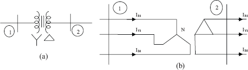
Fig 7.10 Star-Delta Power Transformer Connected Between Buses 1 and 2
Summarizing the above, it can be stated that a transformer can be simply represented as series impedance on a reactance element without verifying the type of transformer winding or the condition of the neutral. Moreover, as Z1 = Z2 for a transformer, both positive and negative sequence networks appear quite similar.
The zero-sequence equivalent circuit of a transformer is not like the others. It is influenced by the type of winding and the condition of the neutral. We shall consider two cases and leave the third to the reader as an exercise.
Case-1: Let the transformer primary be star connected (neutral grounded) and the secondary be delta connected.

Fig 7.11(a) A Star-Delta Transformer for a Zero-Sequence Network
Consider Figure 7.11(a). The transformer is connected between buses 1 and 2. Let the zero-sequence current flow out from generator terminals. These currents can flow into primary winding, provided KCL is satisfied at junction N. The sum of incoming currents to junction N is IR0 + IY0 + IB0 = 3IR0 and the out flowing current is IN0 = 3IR0. This verifies that KCL is valid and that such currents do exist. These primary currents induce secondary currents in the delta connected windings (phases). But the line current on the delta side is zero as the difference between any two phase currents, say for example, IR0 – IY0 = 0. Therefore currents can appear up to the secondary side and return. This is shown in Figure 7.11(b).
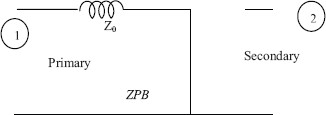
Fig 7.11(b) A Star-Delta Transformer Representation in the Zero Sequence Network
Case-2: Now consider a star-star transformer. The neutral on both sides are grounded solidly. This is shown in Figure 7.12(a).

Fig 7.12(a) A Star-Star Transformer for a Zero Sequence Network
In this case, KCL is satisfied at the junctions on both sides and current can pass from Bus-1 to Bus-2 through the power transformer. In other words, the transformer can act like a series impedance element as shown in Figure 7.12(b).
A current of 3IR0 at the neutral produces a drop of 3IR0 Zn. This effect can be shown in the network by adding 3Zn to Z0 of the transformer.
Switch diagram for the representation of transformer in a zero-sequence network
The switch diagram shown in Figure 7.13 can be used to represent a transformer in the zero-sequence network. The circuit consists of two series switches (1 and 2) and two shunt switches (11 and 21). 1–11 corresponds to the primary and 2–21 corresponds to the secondary side of the transformer. Z0 is the zero sequence impedance of the transformer.
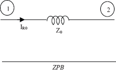
Fig 7.12(b) Representation of a Star-Star Transformer for a Zero Sequence Network

Fig 7.13 Switch Diagram for Representation of Transformer in the Zero-Sequence Network
Rules for using the switch diagram:
- Series switches are closed when the winding is star connected and neutral grounded.
- Shunt switches are closed when the winding is delta connected.
Example: Let the primary side of the transformer be delta connected and the secondary side, star connected with the neutral grounded. Then, switches 11 and 2 may be closed. Other types of connections are given in Example 7.5.
Example 7.5
Give the zero-sequence network equivalent for the transformer connected between buses 1 and 2. Use switch diagram.


7.4.3 Transmission Line Representation
Transmission lines can be represented as series impedance elements in all the three sequence networks. Transmission lines between buses 2 and 3 may be depicted as shown in Figure 7.14. Similar representations may be made for all the three sequence networks. In Figure 7.14, Z1, Z2 and Z0 are the per unit sequence impedance of the respective networks.
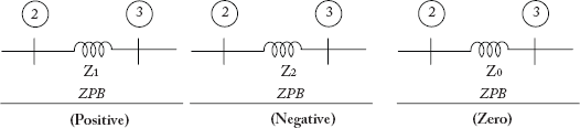
Fig 7.14 Transmission Line Representation for the Three Sequence Networks
Knowledge of representation of individual components helps to convert any power system network into three-sequence networks for the calculation of fault currents in unbalanced fault analysis.
7.4.4 Summary of Sequence Networks
- Only positive sequence network contains voltage sources.
- For equal numerical values of positive and negative sequence impedances, the sequence networks appear quite similar except for the voltage sources present in the positive sequence network.
- Power transformer connection types and the neutral of the generator and the transformer need not be verified while drawing positive and negative sequence networks.
- For a generator, the condition of the neutral may be depicted as given:
- Neutral ungrounded: show open circuit
- Neutral solidly grounded: show short circuit
- Neutral impedance grounded with neutral-to-ground impedance Zn: show generator as impedance element with value Z0. = Zg0. + 0.3Zn, where Zg0 is the zero-sequence impedance of the generator.
- The transformer is represented as a series impedance element both in positive and negative sequence networks. (Remember Z1= Z2 for a transformer)
- Care should be taken while representing a transformer in the zero-sequence network. (Refer Figure 7.13)
- Zero-sequence currents cannot flow if the return path is not available.
- The transmission line is represented as a series impedance element in all sequence networks. (Remember Z1= Z2 for a transmission line)
Example 7.6
Figure 7.15 represents a simple power system. Draw its positive, negative and zero-sequence networks.

Fig 7.15 Simple Power System for Example 7. 6
Solution:
Positive sequence network

Negative sequence network
Zero-sequence network
7.5 Unbalanced or Unsymmetrical Fault Analysis
The following are the types of unbalanced faults:
- Single line-to-ground fault (SLG fault)
- Double line fault (LL fault)
- Double line-to-ground fault (LLG fault)
It has been mentioned in Section 7.4 that fault analysis is also carried out on a single-phase basis, similar to symmetrical fault analysis, with the difference lying in the fact that the former involves working with three-sequence networks instead of with a single network. Though this type of analysis may call for more effort, it is advantageous to work on a single-phase basis. The method of drawing the three-sequence diagram for a given power system network consisting of generators, transformers and transmission lines has also been discussed in earlier sections.
The following steps are involved in unsymmetrical fault analysis. These steps are common to all the three types of balanced faults.
Step 1: Convert the given power system network into three equivalent p. u. sequence networks.
Step 2: Look for the fault location and reduce the three-sequence networks into three Thevenin's equivalents across the fault terminal F and ZPB. Get the Thevenin's positive, negative and zero sequence impedances. Also, obtain pre-fault open circuit voltage E from the Thevenin's equivalent circuit.
Step 3: Obtain the values of sequence currents.
Step 4: Obtain the unbalanced currents using the equation:

Step 5: Obtain the sequence voltages from
where, IR1, IR2, IR0 are previously calculated and Z1, Z2, Z0 are Thevenin's equivalent impedances obtained earlier.
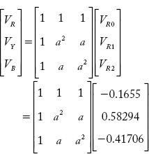
Step 6: Obtain phase voltages from:
This concludes the fault analysis.
7.5.1 Single Line-to-Ground Fault (SLG Fault)
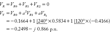
Assume initially that the system is isolated from the load end. The pre-fault balanced condition of the system is:
Now, consider an SLG fault occurring at point F as shown in Figure 7.16.

Fig 7.16 SLG Fault
If is the fault current. The fault has an impedance of Zf. If the fault is a dead short-circuit, then Zf = 0 or VR.= 0 with a fault impedance of Zf. During the fault, the condition of the system is:
To complete the fault analysis, we need the relation between sequence currents and their magnitudes.
Relation between sequence currents:
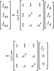
From the above,
The relation between sequence currents for a SLG fault is:
i.e., all the sequence currents are equal. Now, we shall find the magnitudes of the sequence currents:
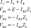
Fault voltage Vf = VR = If Zf = IRZf
In terms of sequence components,
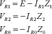
Using Thevenin's equivalent circuits obtained across F and ZPB, the sequence voltages can be written as:
As all the sequence currents are equal,
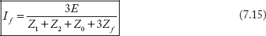
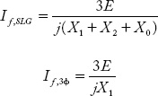
From the above equation, the magnitude of sequence current IR1 is
Since all the sequence currents are equal,

and the fault current is: If = IR = 3IR1
Therefore,
The relations represented by Equations (7.12), (7.13) and (7.14) can be easily obtained by connecting Thevenin's equivalent sequence networks in series as shown in Figure 7.17. Further, the sequence currents may also be computed by using this series circuit.
The next step is finding the sequence voltages as:
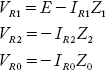
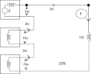
Fig 7.17 Sequence Network Connected in Series for a SLG Fault
and three-phase voltages as:
This concludes SLG fault analysis.
7.5.2 Double Line Fault (LL Fault)
Assume initially that the power system is isolated from the rest of the system, such that IR = IY = IB = 0 and that the three-phase voltages are balanced. Now, assume that a double line fault with a fault impedance of Zf has occurred across Y and B phases as shown in Figure 7.18.
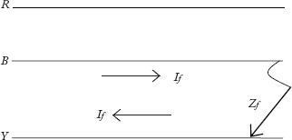
Fig 7.18 LL Fault
During the fault condition of the system:
IR = 0 (due to healthy condition);
Fault current If = IY – IB (for the direction shown)
Relation between sequence currents:
The sequence currents at the fault point are:
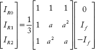
From the above equation,
and ![]()
Therefore the relation between sequence currents for an LL fault is:
Magnitude of sequence currents:
Replacing symmetrical components for VY, VB or If (=IY) in the above equation,
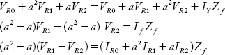
Using Equation (7.16)
Substituting equations for sequence voltages,
As IR2 – IR1, the above equation modifies to:
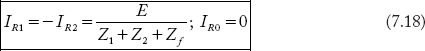
From the above, the magnitude of IR1 is:
where E, Z1, Z2 are Thevenin's equivalent sequence network parameters.
Therefore, the relation may be given by
The fault current If = IY can be obtained as:
but
Substituting a2 – a value, the equation for If is:

and the magnitude of fault current is:
Knowing the values of sequence currents and sequence voltages, three-phase voltages may be obtained by a similar procedure as explained for SLG fault in Section 7.5.1. Sequence networks for the fault can be drawn in series opposition as shown in Figure 7.19
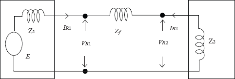
Fig 7.19 Sequence Networks for LL Fault
Figure 7.15 is drawn in accordance with Equation (7.18) and can be used to find and establish sequence currents.
7.5.3 Double Line-to-Ground (LLG) Fault
Let the pre-fault condition of the system be: IR = IY = IB = 0 and the three-phase voltages be balanced. Now, a double line-to-ground fault occurs between Y and B phases to the ground. The fault impedance is Zf. This is shown in Figure 7.20(a).

Fig 7.20(a) LLG Fault on the System
When fault occurs, the condition of the system may be written as:
IR = 0 (due to healthy condition)
If = fault current = IY + IB
Equation (7.18) in sequence components can be written as:
From the above,
From Equation (7.18)
Replacing VY, IY, IB in terms of sequence components,
As
The above equation can be written as
During fault condition,
Substituting the above condition in Equation (7.20),
Equation (7.19, 7.21, and 7.22) can be obtained by connecting the sequence networks in parallel. This is shown in Figure 7.20(b):,
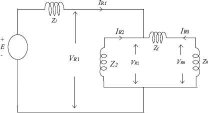
Fig 7.20(b) Connection of Sequence Networks for LLG Fault
In Figure 7.20(a), Equations (7.19, 7.21 and 7.22) can be proved.
Relation between sequence currents:
If Zf = 1 (dead short-circuit), all the sequence voltages are equal. This means all the sequence networks are connected in parallel for an LLG fault. Using Figure 7.20(a), the magnitude of sequence currents can be found as:
IR1 = Total current in the circuit
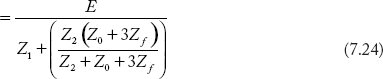
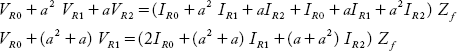
where E, Z1, Z2 and Z3 are Thevenin's equivalences of positive, negative and zero sequence networks. Using current division formula
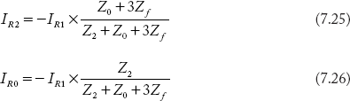
Equations (7.24–7.26) can be used to determine sequence currents. Using these sequence currents, the fault current and sequence voltages can be obtained as:
Using the sequence voltages, all the three phase voltages can be obtained as:

This concludes LLG fault analysis.
7.5.4 Three-Phase Symmetrical Fault in Terms of Sequence Components
Under balanced condition
This means that, symmetrical fault analysis requires only the positive sequence network as shown in Figure 7.21.

Fig 7.21 Three-Phase Fault
Figure 7.21 is the Thevenin's equivalent circuit obtained using positive sequence network across faulted point F and ZPB.
- The three phase fault current

- The positive sequence voltage at the point of fault location is VR1 = 0 (voltage across short circuit)
Summary of Faults
- All types of faults consist of positive sequence networks.
- All types of unsymmetrical faults consist of negative sequence network
- If the fault involves the ground (return path available) then
- zero sequence network is present
- zero sequence currents can flow.
- All the sequence networks are connected in series for an SLG fault and in parallel for an LLG fault.
- All sequence currents are equal for an SLG fault and all sequence voltages are equal for an LLG fault.
- The current flowing through the fault in the case of a three-phase fault is zero because of symmetry. However, the fault across the three phases raises the current in all the three phases.
- All sequence voltages, including positive sequence voltages are zero for a three-phase fault.
7.6 Comparison of SLG and 3-Phase Faults
When the fault involves only one phase, fault current is expected to be the least. Where as, involvement of all the three phases gives rise to the highest fault current. A comparison of these two faults, when they occur on the terminals of various equipments is presented in this section. Let the sequence impedance Z1, Z2 and Z0 be pure reactances, and consider a dead short-circuit with Zf = 0. The three-phase and SLG fault currents are given by:
Case-1: Ungrounded neutral alternator
When the fault is at generator terminals with the generator neutral grounded, Z0 = ∞.
Case-2 : Solidly grounded neutral alternator
In this case, the zero-sequence reactance of the generator is X0 = Xg0 + 3Xn = Xgo (as Xn = 0 for solidly grounded neutral case)
The following relations are valid for the generator:
![]() (for the sub-transient state)
(for the sub-transient state)
Substituting the above relations,
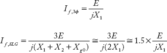
From the above,
It is seen that for the solidly grounded neutral alternator, an SLG fault is more than a three-phase fault.
Case-3: Generator neutral reactance grounded
Generator neutral is grounded through reactance Xn. Xn has no effect on the magnitude of the three-phase fault, but it is designed as ![]() Substituting Xn value of the above and following the relations between sequences of the generator, the SLG fault current is:
Substituting Xn value of the above and following the relations between sequences of the generator, the SLG fault current is:
This means, for the designed value of Xn, the SLG fault current is equal to the three-phase fault current. For different values of Xn, the relations are shown below:
| Xn value | Relation |
|---|---|
Case-4 Faults on Transformer / Transmission line
For the transformer and transmission lines of static devices, X0 >> X1. For this relation of reactances, a three-phase fault is always the reverse of an SLG fault.
7.7 Consideration of Pre-Fault Load Currents
The exact value of current during the faulty condition of a system can be obtained by superimposing pre-fault load currents on to the fault currents. The following presents the procedural steps:
- Calculate the pre-fault load current.
- Calculate the pre-fault voltage at the fault point (this voltage value is to be considered in the positive sequence network).
- For the given single-line diagram, draw the three-sequence networks.
- Obtain the Thevenin's equivalent sequence networks and interconnect the sequence networks depending upon the type of fault.
- Calculate sequence component currents of fault at different locations in the network.
- Sequence components of fault current at different locations are added to the same type of sequence components of pre-fault load currents at the same locations. If the load is balanced, only the positive sequence currents need to be superimposed.
Example 7.7
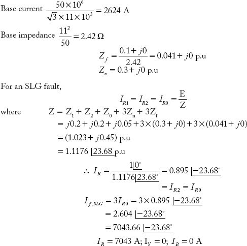
An alternator rated 11 kV, 50 MVA with neutral solidly grounded has X1 = X2 = j0.1 p. u. and X0 = j0.05 p.u. It is supplying power to an 11 KVA, 25 MVA motor which has X1 = X2 = j0.1 p.u and X0 = j0.05 p.u. through a short transmission line. Line reactances are X1 = X2 = j 0.01 p.u and X0 = j0.4 p.u. All the equivalent reactances are pre-calculated on a 50 MVA, 11 KV base. The motor is drawing a power of 25 MW at 0.866 lag. The motor terminal voltage at loaded condition is 0.95 p. u. An SLG fault occurs on the phase-R of the generator. Calculate the fault current in phase-R of the generator under the given fault conditions.
Solution:
Taking the motor voltage as reference, the load current lags it by 30°.
Considering the positive sequence network of the system

Fig 7.22(a) Positive Sequence Network
Terminal voltage of generator = V
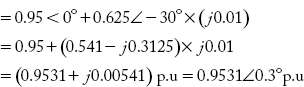
Fig 7.22(b) shows the interconnection of sequence networks for an SLG fault

Fig 7.22(b) Interconnection of Sequence Networks for an SLG Fault
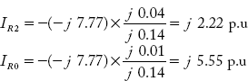
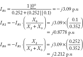
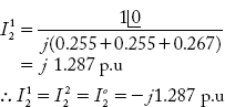
The sequence components of the fault are

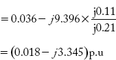
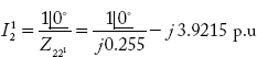
The component of positive sequence fault current flowing through the generator is
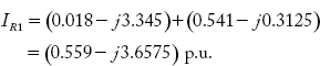
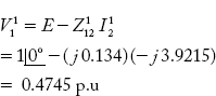
As the load current is a fully positive sequence, the total positive sequence component current during the fault is:
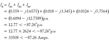
Negative sequence component current through generator (0.018 – j3.345) p.u. Zero sequence component current through the generator

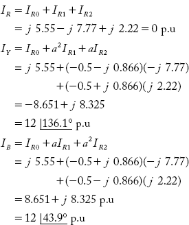
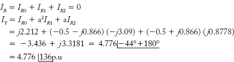
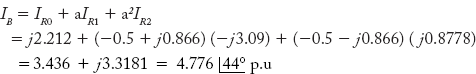
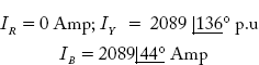
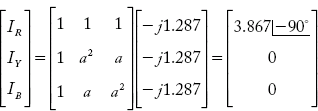
The total current through Generator is
Example 7.8
Figure 7.23 shows a simple power system network. Draw the positive, negative and zero sequence networks.
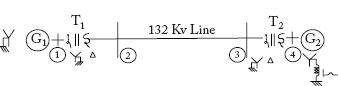
Fig 7.23 A Simple Power System Network
The numerical data of various components in the power system is given as under: (all values are in p. u.)
Generator G1: 50 MVA, 11 KV, X1 = X2 = 0.2; X0 = 0.01;
Generator G2: 100 MVA, 11 KV, X1 = X2 = 0.25; X0 = 0.02;
Transformer T1: 50 MVA, 11/132 KV, X1 = X2 = 0.2; X0 = 0.4
Transformer T2: 100 MVA, 11/132 KV, X1 = X2 = 0.1; X0 = 0.1
132 KV Line: 100 MVA, 132 KV, X1 = X2 = 0.1; X0 = 0.25
Solution:
Common base MVA = 100 MVA;
Base voltage on LT side = 11 KV
Base voltage on HT side = 132 KV
Equipment per unit sequence impedances and common base values are completed below.
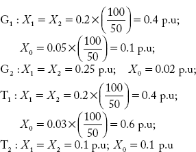
132 KV Line: X1 = X2 = 0.1; X0 = 0.25 p.u
G2 (neutral-ground reactance)

The pre-fault induced emf of G1 and G2 are assumed as 1 p. u.
a) Positive sequence network:

b) Negative sequence network:

Example 7.9
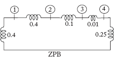
For the network in Example 7.8, simulate fault on Bus-3. Obtain Thevenin's equivalent positive, negative and zero sequence networks.
Solution:
Thevenin's equivalent circuit of positive, negative and zero sequence networks across Bus-3 and ZPB are obtained as follows:
a) Thevenin's equivalent positive and negative sequence networks:
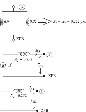
b) Thevenin's equivalent zero-sequence network

The part of the network on the left hand side of Bus-3 is not considered due to discontinuity at Bus-2.
Example 7.10
A single line-to-ground fault occurs at Bus-3 of the network of Example 7.8; using Thevenin's equivalent sequence networks obtained in Example 7.9, determine the faulty phase and healthy phase:
a) Currents
b) Phase voltages
c) Line-to-line voltages
Solution:
(a) Thevenin's equivalent sequence reactance are obtained in Example 7.7. X1 = X2 = j0.252 p. u, X0 = j0.1 p. u.
Sequence currents are equal for an LG fault
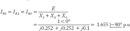
Assuming a fault in an R-phase
The magnitude of SLG fault current
Current in all phases
(b) Sequence voltages at the fault point are:
The three-phase voltage (phase) values are:

Thus, line-to-neutral voltages at the fault point are:

Example 7.11
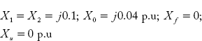
A synchronous generator rated 3-phase 11 KV, 100 MVA has X1 = X2 = j0.1 p.u and X0 = j0.04 p.u. Determine the fault current and line-to-line voltages during the fault condition: (a) if a single line-to-ground (SLG) fault occurs on the generator terminals, (b) if the generator neutral is solidly grounded, (c) if the generator is operating at no-load and rated voltage prior to the fault.
Solution:
It is usual practice for the rating of the equipment to be taken as base values.
For an SLG fault
Sequence voltages at fault point are:

Phase voltages at fault point are:

Line-to-line voltages
since, the generator line-to-neutral voltage is taken as 1 p.u.


Example 7.12
Consider the power system shown in Figure 7.24.
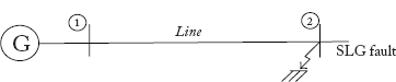
Fig 7.24 Power System Network of Example 7.12
An SLG fault occurs at Bus-2 at the far end of the line. Consider the numerical data:
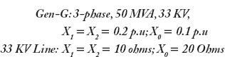
Determine the fault current magnitude:
- If the generator neutral is solidly grounded and fault impedance is zero
- If the generator neutral is solidly grounded and fault impedance is 0.1 p. u on 50 MVA, 33 KV.
- If the generator neutral is reactance grounded with Xn = 0.1 p. u on 50 MVA, 33 KV and fault impedance is 0.1 p. u on 50 MVA, 33 KV.
Let Base MVA = 50 MVA
Base voltage = 33 KV
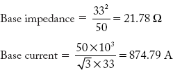
Line sequence reactance in p.u

- Total sequence reactance upto the fault location:
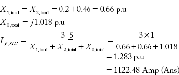
-

-

Example 7.13
Consider the power system of Example 7.12.
- If a three-phase fault occurs at the end of the line, compute the fault current.
- Compare the three-phase fault current with an SLG fault for the conditions (a) to (c)

Example 7.14
Consider the synchronous generator of Example 7.11. Determine the fault current and line-to-line voltages if a double line fault occurs on the generator terminals.
Solution:
For LL fault,

Now, the line current is:

For LL fault,
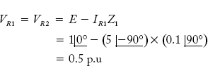
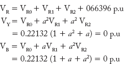
Line-to-neutral phase voltages are:
While calculating the sequence [1 + a + a2 = 0] the current and line-to-neutral voltage (phase voltage) are taken as 1 p.u

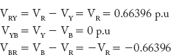
Line-to-line voltages

Example 7.15
Consider the synchronous generator of Example 7.11. Determine the fault current and line-to-line voltages if a double line-to-ground fault occurs at the generator terminals
Solution:
Positive, negative and zero sequence networks are connected in parallel as shown in Figure 7.25.
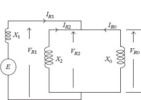
Fig 7.25 Thevenin's Equivalent Sequence Networks Connected in Parallel for an LLG Fault
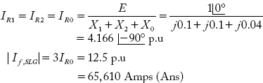
From the figure,

Using the current division formula,
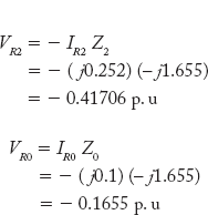
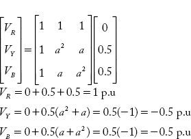
The line currents in R, Y and B are:
For an LLG fault, all the sequence voltages are equal.

Line-to-neutral voltages of the generator are:
Since 1 p.u voltage ![]() KV
KV
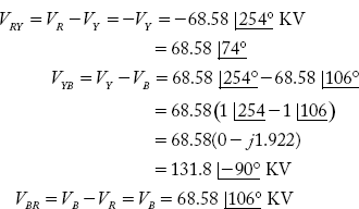
Line voltages
Example 7.16
Consider the power system of Example 7.8 and Thevenin's equivalent sequence networks obtained in Example 7.9. Determine the magnitude of fault current if a double line (LL) fault occurs on Bus-3.
Solution:
Thevenin's equivalent sequence networks for LL fault are connected as shown in Figure 7.26

Fig 7.26 Sequence Networks for Double Line Fault
Considering data E = 1 ![]() X1 = X2 = 0.252 p.u
X1 = X2 = 0.252 p.u

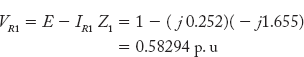
Sequence voltages

Phase voltages at the location of fault are:

Line voltages at the location of fault are:

Since sequence currents are computed by considering line-to-neutral voltage as 1 p. u, the base voltage taken in the problem is:

Example 7.17
Consider the power system of Example 7.8 and Thevenin's equivalent sequence networks obtained in Example 7.9. Determine the magnitude of fault current if a double line- to-ground fault (LLG) occurs on Bus-3. Assume fault impedance as zero.
Solution:
All the three sequence networks are connected in parallel for an LLG fault as shown in Figure 7.27.
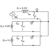
Fig 7.27 Sequence Networks Connected in Parallel for an LLG Fault
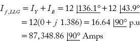
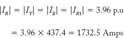
Line current in the three phases are:
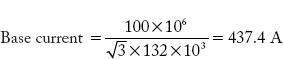
Base current = 437.4 Amp (ref Example 7.10)
Fault current:

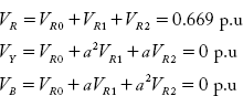
Sequence voltages

Phase voltages at fault location
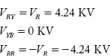
Line voltages at fault location
While calculating sequence voltages, phase voltage E is taken as 1 p.u.
Therefore, 1 p.u voltage at fault location

Example 7.18
Consider the power system of Example 7.7 and Thevenin's equivalent sequence networks obtained in Example 7.9. Determine the magnitude of fault current if a symmetrical three-phase fault current occurs on Bus-3.
Solution:
For symmetrical faults, only positive sequence network is considered.
Fault currents in lines are:
Line voltages at the fault location
Since VR1 = VR2 = VR0 = 0 all line voltages are zero at the fault location.
Example 7.19
Three faults simulated on a power system give the following results:
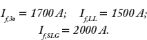
The base values at the fault location are: 100 MVA, 132 KV. Find the p. u values of all sequence impedances of Thevenin's equivalent networks.
Solution:

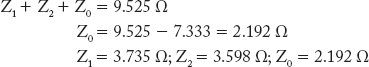
Example 7.20
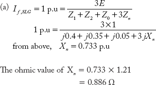
A three-phase generator noted 10 MVA, 11 KV has a solidly grounded neutral. The sequence impedances of the alternator are: Z1 = j 0.4; Z2 = j 0.35 and Z0 = j 0.05 p.u. The resistances are negligible. What value of (a) reactance and (b) resistance must be placed in general neutral for a single line-to-ground fault of zero fault impedance to the rated line current?
Solution:
Taking equipment rated values as base, the generator rated current:
Base impedance
1 p.u current = 524.87 A

Example 7.21
Consider the generator of Example 7.20. What value of reactance is needed to connect from neutral to ground, such that the three-phase fault and SLG fault currents are equal?
Solution:
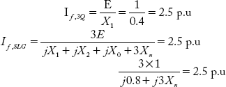
Solving the above,
Example 7.22
A three-phase 50 MVA, 11 KV star-connected alternator neutral is grounded through a 30% pure resistor. It has X1 = X2 = 20% and X0 = 5% when the generator is unloaded. A single line-to-ground fault occurs on the R-terminal through a fault impedance of 0.1 + j0 ohms. Determine fault currents in all the phases and also the earth fault current.
Solution:
Taking equipment rating as base values,
7.8 Fault Calculations Using Bus Impedance Matrix
Symmetrical fault analysis and unsymmetrical fault analysis for a small power system can be carried out by the procedure discussed in Chapter 6. However, for large power systems obtaining Thevenin's equivalent circuit is quite tedious and difficult. Fault analysis for large interconnected power systems can be easily performed by using the bus impedance matrix. The reader should refer to Chapter 3 to understand the algorithm for a bus impedance matrix (ZBus). The three sequence networks are first converted into graphs using the building algorithm for ZBus and the three different sequences of bus impedance machines are initially given names Z1,Bus, Z2,Bus and Z0,Bus. For an n-bus power system the size of these machines are (n × n).
The following mutations are used in the analysis.
Let,
V1,Bus = Positive sequence bus voltage matrix of dimension (n × 1), for Kth bus VK1
V2,Bus = Negative sequence bus voltage matrix of dimension (n × 1), for Kth bus VK2
V0,Bus = Zero-sequence bus voltage matrix of dimension (n × 1), for Kth bus VK0
Similarly, buses I1, I2, and I0 represent three sequence currents with general entries for the Kth bus as IK1, IK2 and IK0 respectively.
EBus = Pre-fault voltage matrix of dimension (n × 1), all elements being equal to ![]() p. u
p. u
Matrices representing sequence voltages can be obtained from:
Analysis of all types of faults using ZBus
Short circuit analysis can be carried out by using Equations (7.28–7.30).
Assume that a fault has occurred at Bus K in an n-bus power system. Initially, the system is working under no fault condition.
7.8.1 Three-Phase Symmetrical Fault
For a three-phase fault, a symmetrical fault corresponding to negative and zero- sequence components does not exist except in the case of positive sequence machines.
Now, the Kth entry of V1,Bus is:
All bus currents except the Kth bus are zero,

Vk1 at the fault location can also be written as,
i.e, the Kth bus voltage is potentially higher by IK1 Zf, where Zf is the fault impedance from Equations (7.31) and (7.32). The symmetrical fault current is
The healthy bus voltages are:

7.8.2 Single Line-to-Ground Fault
For an SLG fault, all sequence currents are equal.
All sequence currents at other healthy buses are zeros
The K 15 bus voltage is potentially higher than ZPB by
The sequence voltages are:

Substituting Equations (7.36–7.38) in (7.35) we get,

The result of Equation (7.39) can be substituted in Equations (7.36)–(7.38) to evaluate sequence voltages.
SLG fault current at the Kth bus is:

The sequence voltages of other healthy buses can be computed as:

and i15 bus voltage is:
7.8.3 Double Line Fault (LL Fault)
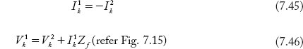
For an LL fault,
In the positive and negative sequence methods, the lines are connected in series opposition and the following equations can be used
Using Equations (7.36) — (7.38), Equation (7.46) is modified as:

From the above equation,
Now, the fault current in the Y-phase of Kth bus is:
The sequence voltages of other healthy buses can be computed as:

I1k is computed using Equation (7.47)
7.8.4 Double Line-to-Ground Fault
For an LLG fault,

From the equivalent circuit drawn for an LLG fault, we can write:
From Equations (7.36–7.38)
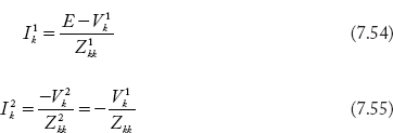
Using Equation (7.53),

Substituting Equations (7.54 to 7.55) in Equation (7.52),
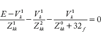
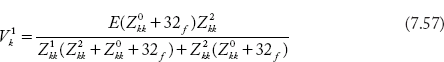
The denominator in the Equation (7.57) can be represented as Z. Substituting Equation (7.57) in Equations (7.54) — (7.56)

where Z = Z1kk(Z2kk + Z0kk + 3Zf) + 22kk(Z0kk + 32f)
Using Equations (7.58) — (7.60), the sequence currents can be determined through which the LLG fault can be computed as:
If1,LLG = Y-phase current of Kth bus
+ B-phase current of Kth bus
The Y and B phase currents can be calculated using sequence currents of Ik
Other healthy bus voltages can be computed as given below:

for i = 1, 2,…, n, i ≠ k.
Ik0 Ik1 and Ik2 can be computed by using Equations (7.54 — 7.56)
Example 7.23
A single line-to-ground fault on phase-R occurs on Bus-2 in the system of Figure 7.28(a)

Fig 7.28(a) A Two-Bus Power System

Compute the following in per unit
Bus impedance matrix of positive, negative and zero-sequence networks
Fault current and healthy phase voltages
Solution:
The passive positive and negative sequence networks are represented by the circuit shown in Figure Ex 7.28(b) and zero sequence network in Figure 7.28(c).

Fig 7.28(b) Positive and Negative Passive Sequence Network

Fig 7.28(c) Passive Zero-Sequence Network
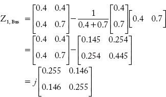
a) Formation of positive and negative sequence bus impedance matrices.
Step-1: Adding element from Reference to Bus-1,
Step-2: Adding element from Bus-2 to Bus-1,
Step-3: Adding element from Bus-2 to Reference,
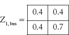
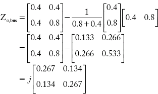
Formation of ZBus
With reference to Figure 7.23 (b), Z, Bus is obtained below
Step-1: Adding element from Reference bus to Bus-1
Step-2: Adding element from Bus-1 to Bus-2

Step-3: Adding element from Bus-2 to Reference
(b) An SLG fault occurs on Bus-2. Using Equation (7.39), the sequence currents are (zf = zn = 0):
The line currents at Bus-2 are
Using Equations 7.41–7.43, the sequence voltage of healthy Bus-1 can be competed.

and V1 = V10 + V11 + V12
= 0.419 p.u (Ans)
Example 7.24
Repeat the Example 7.23, if a 3-phase fault occurs on Bus-2.
Solution:
Using Equation (7.33),
For 3 fault, I20 and I20 are absent.
The line currents at faulted Bus-2 are:

Using Equation (7.34), the healthy Bus-1 voltages can be computed.
For a symmetrical fault V12 = V10 = 0
The line-to-neutral voltages at Bus-1 are:
Example 7.25
Repeat the Example 7.23, if a double line fault occurs at Bus-2.
Solution:
Using Equation (7.47)
Line currents at the faulted Bus-2 are:

From the above, ![]()

The sequence voltages of healthy Bus-1 can be computed by using Equations 7.49 and 7.50

Phase-to-neutral voltage at Bus-1 is:

Example 7.26
The positive sequence bus impedance matrix of a 4-Bus power system network is given below:
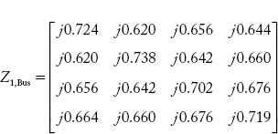
Calculate the fault current, if a symmetrical fault occurs on Bus-2.
Solution:
Using Equation (7.33),

The line currents in R, Y and B Phases at Bus-2 are:

Example 7.27
Consider the data given in Example 7.26 for the 4-bus system. The positive and negative bus impedance matrices are the same. Find the magnitude of fault current if an LL fault occurs at Bus-3.
Solution:
Using Equation (7.47)

using Eq.(7.48);

If the base current is known, the magnitude of fault current in amperes can bedetermined.
Questions from Previous Question Papers
- (a)Draw the positive, negative and zero-sequence networks for a system described as follows. The system consists of a 3-ø star connected to a synchronous motor through a delta-star step-up transformer, a transmission line and a star-delta step-down transformer. The neutral points of the machine windings are solidly grounded and the transformer winding neutrals are ungrounded.
(b) Explain the concept of sequence impedance of a 3-ø star connected, rotating load whose neutral is grounded through some impedance and draw its sequence impedance networks
- A 3-ø alternator is supplying power to the star-connected load through a feeder. The alternator per phase impedance is equal to Zs and the load impedances are ZR, ZY and ZB in the R, Y, B phases respectively. Neglect the feeder impedance. Derive the expression for phase currents and phase voltages at the load end, when there is a line-to-ground fault at the R phase. Assume that both neutrals are solidly grounded.
- A 3-ø, 400 V, 1 MVA alternator having per-phase reactance of 3Ω and negligible resistance, is supplying power to a star-connected load having reactances 10 Ω, 20 Ω, and 15 Ω in the R, Y, and B phases respectively. Calculate the fault current and phase voltages at the load side, when a line-to-ground fault occurs at the middle of the feeder at the R phase. Assume that both neutrals are solidly grounded.
- Derive the expression for the fault current and terminal voltages for a line-to-ground fault which occurs at the terminals of an unloaded 3-ø, alternator. Assume that the alternator has an isolated neutral.
- A 20MVA, 11KV, 3-ø, 50 Hz generator has its neutral earthed through a 5% reactor. It is in parallel with another identical generator having its neutral earthed through a 5% reactor. Each generator has positive, negative and zero sequence reactances which are 20%, 10%, and 15% respectively. If a line-to-ground short circuit occurs in the common bus bar, determine the fault current.
- (a) What are symmetrical components? Why are they used in power system fault analysis? Explain in detail.
(b) Obtain the symmetrical components of the following set of unbalanced currents:

- (a) Derive an expression for the fault current and terminal voltage of the three different phases of an alternator, when a double line-to-ground fault occurs at the R-Phase. Assume that the alternator neutral is isolated
(b) A 3-ø, 11 KV, 25 MVA Generator with X0 = 0.05 per unit and X1 = 0.2 per unit is grounded through a reactance of 0.3 Ω. Calculate the fault current for a double line-to-ground fault. Also calculate the terminal voltage of the faulted phase.
- (a) Draw the sequence diagram for a single line-to-ground fault and derive the equation for the fault current. Assume that the generator neutral is solidly grounded and that the generator terminals are open-circuited.
(b) A 30 MVA, 11 KV, 3-ø synchronous generator has a direct sub-transient reactance of 0.25 per unit. The negative and zero-sequence reactances are 0.35 and 0.1 per unit respectively. The neutral of the generator is solidly grounded. Determine the sub-transient current in the generator and the line-to-line voltages for sub-transient conditions when a single line-to-ground fault occurs at the generator terminals with the generator operating unloaded at rated voltage.
- (a) Derive the expression for fault current and terminal voltages of a 3-ø alternator, when there is a line-to-line fault at the far end of the alternator. Assume that the generator neutral is solidly earthed. [8-8]
(b) A 3-ø, 11KV, 25MVA generator with X0 = 0.05 p.u., X1 = 0.2 p.u. is grounded through a reactance of 0.3. Calculate the fault current for a single line-to-ground fault. Also calculate the terminal voltage of the faulted phase with respect to the ground.
- (a) What are the direct unsymmetrical faults? Compare their characteristics.
(b) A 3-ø, 11 KV, 25 MVA generator with X0 = 0.05 p.u., X1 = 0.2 p.u. is grounded through a reactance of 0.3. Determine the ratio of fault current of double line-to-ground fault to the single line-to-ground fault, considering one fault at a time.
(c) Derive the formulas used in the above problem
- (a) Draw the positive, negative and zero sequence networks for the system described as follows: The system consists of a 3-ø star-connected alternator supplying power to the 3-ø star-connected synchronous motor through a delta-star step-up transformer, a transmission line and a star-delta step-down transformer. The neutral points of the machine windings are solidly grounded and the transformer winding neutrals are un grounded. [10 + 6].
(b) Explain the concept of sequence impedances of a 3-ø star-connected rotating load whose neutral is grounded through some impedance, and draw its sequence impedance networks.
- (a) Obtain the expressions for sequence impedances of a 3-ø, 3-wire un-transposed transmission line. Also draw the sequence impedance networks. Assume that the transmission line is having mutual impedance from phase-to-phase.
(b) Obtain the expressions for sequence impedances of a 3-ø, 3-wire transposed transmission line. Also draw the sequence impedance networks. Assume that the transmission line is having mutual impedance from phase to phase.
(a) A 3-ø alternator is supplying power to the star-connected load through a feeder. The alternator per phase impedance is equal to ZS and the load impedances are ZR, ZY and ZB in R-, Y- and B-phases respectively. Neglect the feeder impedance. Derive the expression for phase currents and phase voltages at the load end, when there is an open conductor fault at the R-phase. Assume both neutrals are solidly grounded.
(b) A 3-ø, 400 V, 1 MVA alternator has per-phase reactance of 3 Ω and negligible resistance supplying power to a star-connected load having reactances 10 Ω, 20 Ω, and 15 Ω in R-, Y-, and B-phases respectively. Calculate the phase currents and phase voltages at the load side, when an open conductor fault occurs at the R-phase of the feeder. Assume that both neutrals are solidly grounded.
- The currents in a 3-phase unbalanced system are:
IR = (12 + j6); IY = (12 - j12) A
IB = (-15 + j10) A
The phase sequence is RYB. Calculate the zero, positive and negative sequence components of the currents.
- Three resistors of 5 ohms, 10 ohms and 20 ohms are connected in Delta across the three phases of a balanced 100 Volts supply. What are the sequence currents in the resistors and in the supply lines?
- What are symmetrical components? Why are they used in power system fault analysis? Explain in detail.
- Derive the expression for neutral current in a three-phase four-wire balanced load which is connected to a 3-phase four wire balanced source in terms of symmetrical components.
- Bring out the relationship between symmetrical components and unbalanced phases.
- A 3-phase unbalanced system currents are read as IR = 150A; IY = 130A and IB = 10A
- Determine the unbalanced phase voltages VR, VY and VB in a circuit where

- Draw the positive, negative and zero sequence impedance diagrams for different 3-phase transformer winding connections.
- Draw the positive, negative and zero sequence networks for the system described as follows: The system consists of a 3-phase star connected alternator is supplying power to the 3-phase star connected synchronous motor through a delta-star step up transformer, a transmission line and a start-delta steps down transformer. The neutral points of the machine and transformer windings are grounded through the impedance Zn.
- Derive the expressions for sequence impedances and draw the sequence impedance diagrams for a 3-phase synchronous generator whose stator winding neutral is solidly grounded.
- What are the different unsymmetrical faults & Compare their characteristics.
- Derive the expression for the faults current and the terminal voltages for a line to ground fault occurs at the terminals of an unloaded 3-phase alternator. Assume that the alternator neutral is solidly grounded. a) neglect Zfault (b) consider Zfault
- Derive the expression for fault current and the terminal voltages of a 3-phase alternator, when there is a line-to-line fault occurs at the far end of the alternator. Assume that the generator neutral is solidly earthed.
- Derive the expressions for the fault current and the terminal voltages of a 3-phase alternator, when there is a double line to ground fault occurs at the terminals of Alternator. Assume generator neutral is solidly earthed.
- Neglect fault inpedance Zfault
- Consider fault inpedance Zfault
- A 30MVA, 11KV 3 synchronous generator has a disrect subtransient reactance of 0.25 p.u. The negative and zero sequence reactances are 0.35 and 0.1 p.u. respectively. The neutral of the generator is solidly grounded. Determine the subtransient current in the generator and the line to line voltages for the subtransient conditions when a LG fault occurs at the generator terminals with the generator operating unloaded at the rated voltages.
- A 15MVA, 11 KV, 3-phase synchronous generator with solidly grounded neutral has a sub-transient reactance of 25%. The negative and zero sequence reactances are 35% and 10% respectively. Determine the subtransient currents in the generator and line to line voltages when a line to line fault occurs at the terminals of an unloaded generator operating at rated voltage. Resistance may be neglected.
- A 3-phase, 11KV, 25MVA generator with X1 = X2 = j0.2 p.u. and x0 = j 0.05 p.u is grounded through a reactance of Xn = j 0.3 ohms. Determine the ratio of fault currents of double line to ground fault to the single line to ground fault, considering one fault at a time.
- The positive, negative and zero sequence reactances of a 20MVA, 13.2KV synchronous generator is solidly grounded and is not loaded. A double line to ground fault occurs on generator terminals Y and B. Find fault current and line voltages.
- A 50Hz, 13.2 KV, 15 MVA alternator has X1 = X2 = 20% and X0 = 8% and the neutral is grounded through a reactor of 0.5 Ohm. Determine the initial symmetrical RMS current in the ground reactor when a double line to ground fault occurs at the generator terminals at the time when the generator voltage was 12Kv.
Competitive Examination Questions
- The positive sequence component of the voltage at the point of fault in a power system is zero for a ________ fault.
[GATE 1995]
- For an unbalanced fault with paths for zero-sequence currents, at the points of fault
- the negative and zero-sequence voltage are minimum
- the negative and zero-sequence voltages are maximum
- the negative sequence voltage is minimum and zero sequence voltage is maximum
- the negative sequence voltage is maximum and zero sequence voltage is minimum
[GATE 1996]
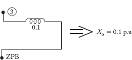
- For the network shown in the given figure, the zero-sequence reactances in p.u. are indicated.
The zero-sequence driving point reactance of the Node 3 is
- 0.12
- 0.30
- 0.10
- 0.20

[GATE 1998]
- A generator is connected to a transformer, which feeds another transformer through a short feeder. The zero-sequence impedance values are expressed in p. u on a common base and are indicated in Figure 7.30. The Thevenin equivalent zero-sequence impedance at point B is
- 0.8 + j0.6
- 0.75 + j 0.22
- 0.75 + j 0.25
- 1.5 + j 0.25
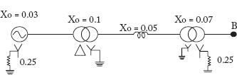
[GATE 2002]
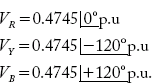
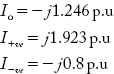
- A three-phase alternator generating unbalanced voltages is connected to an unbalanced load through a three-phase transmission as shown in the figure. The neutral of the alternator and the star point of the load are solidly grounded. The phase voltage of the alternator are
 The positive-sequence component of the current is
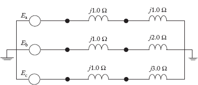

[GATE 2003]
- The percentage of occurrence of the following fault is more:
- SLG
- LL
- LLG
- 3-Phase
- All sequence currents are equal for the following fault:
- SLG
- LL
- LLG
- 3-Phase
- All sequence voltages are equal for the following fault:
- SLG
- LL
- LLG
- 3-Phase
- All sequence networks are connected in series for the following fault:
- SLG
- LL
- LLG
- 3-Phase
- All sequence networks are connected in parallel for the following fault:
- SLG
- LL
- LLG
- 3-Phase
- All sequence voltages at the fault location are zero for the following fault:
- SLG
- LL
- LLG
- 3-Phase
- Zero-sequence currents shall flow
- when SLG and LLG fault Occurs
- all transformers are star-star type
- when return path is available
- when the neutral is only reactance grounded
- For a particular type of fault in a power system, the sequence currents are recorded as:
The fault that has occurred is
- LL
- LLG
- SLG
- 3-Phase
- The ZBus of a system is
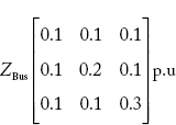
If a 3-Phase fault occurs at Bus-2, the p.u fault current in each phase is

- Tick the correct statement:
- The negative and zero sequence voltages are maximum at the fault location and decrease towards neutral.
- The negative and zero sequence voltages are minimum at the fault point and increase towards neutral.
- The negative sequence is maximum and zero-sequence is minimum at the fault point and decrease and increase respectively towards the neutral.
- The negative sequence and zero-sequence currents do not exist at the fault location.
- A generator has 0.1 p.u impedance. Its short-circuit current in p.u. is
- 20 p.u
- 10 p.u
- 5 p.u
- 0.1 p.u
- For SLG fault shown, the zero-sequence current at Bus-3 is (take = j3 p.u)

- j3 p.u
- j9 p.u
- j3√3 p.u
- 0 p.u
- The nature of the following combination faults as seen by the generator in the network shown is the same.
- LL and LLG
- 3-Phase and SLG
- LL and LLG
- SLG, LL and LLG
- The SLG fault current in the faulted phase is 300 A, the zero-sequence current is
- Zero
- 300 A
- 100 A
- 66.6 A
- The simulated faults on a 100MVA, 11KV 3-Phase generator give
The p.u X1 and X2 of the machine are:
- 0.1, 0.2
- 0.2, 0.1
- 0.1, 0.1
- 0.2, 0.2
- A fault occurring at the terminals of an unloaded synchronous generator operating at its rated voltage has resulted in the following values of current and voltage.
Ia0 = j2.37p.u.
Ia1 = j3.05p.u
Ia2 = j0.68 p.u.
Va0 = Va1 = Va2 = 0.237 p.u.
The fault that has occurred is_____________.
[GATE 1991 Q.No.5]
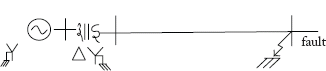
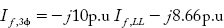
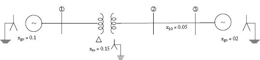
A single line diagram of a power system is shown in figure, where the sequence reactances of generator (G), synchronous motor (M) and transformers (T1,T2) are given in per unit. The neutrals of the generator and transformers are solidly grounded. The motor neutral is grounded through a reactance Xn = 0.05 per unit. Draw the positive, negative and zero sequence networks with reactance values in per unit on a 100 MVA, 13.8 kV base in the zone of the generator. The pre-fault voltage is 1.05 < 20 per unit.
Calculate the per unit fault current for a three-phase to ground fault at bus ‘d’. The system data are as follows:
G - 100 MVA; 13.8 kV; X1 = 0.15; X2 = 0.17; X0 = 0.05
T1,T2-120 MVA; 13.8 kV/138 kV∆/Y; X=0.12
M - 100 MVA; 13.8 kV; X1 = 0.2, X2 = 0.21, X0= 0.1; Xn = 0.05
Line — X1=X2=20 ohms; X0 =60 Ohms
[GATE 1992 Q.No.7]
- In a power system, the 3-phase fault MVA is always higher than the single-line-to-ground fault MVA at a bus. (True/False)
[GATE 1994 Q.No.1]
- A 250 MVA, 11 kv, 3 phase generator is connected to a large system through a transformer and a line as shown in figure below.

The parameter, on 250 MVA base, are as follows:
Generator : X1 = X2 = 0.15 p.u, X0 = 0.1 p.u Transformer : 11/220 kV, 205 MVA X1 = X2 = X0 = 0.12 p.u. Line: X1 = X2 = 0.25 p.u., X0 = 0.75 p.u. Equivalent system X1 = X2 = X0 = 0.15 p.u.> - Draw the sequevce network diagram for the system and indicate the p.u. reactance values.
- Find the driving point impedances of node 2.
- Find the fault MVA for a single line to ground fault at node 2. assume the prefault voltages at all the nodes to be 1.0 p.u.
[GATE 1994 Q.No.8]
- The positive sequence component of the voltage at the point of fault in a power system is zero for a ______________ fault.
[GATE 1995 Q.No.8]
- A three-phase star-connected alternator is rated 30 MVA, 13.8 kV and has the following sequence reactance values:
X1 = 0.25 p.u; X2 = 0.35 p.u and X0 = 0.10 p.u
The neutral of the alternator is solidly grounded. Determine the alternator line currents when a double line-to-ground fault occurs on its terminals. Assume that the alternator is unloaded and is operating at rated voltage when the fault occurs.
[GATE 1995 Q.No.16]
- For an unbalanced fault, with paths for zero sequence currents, at the point of fault
- the negative and zero sequence voltages are minimum.
- the negative and zero sequence voltages are maximum.
- the negative sequence voltage is minimum and zero sequence voltage is maximum.
- the negative sequence voltage is maximum and zero sequence voltage is minimum.
[GATE 1996 Q.No.6]
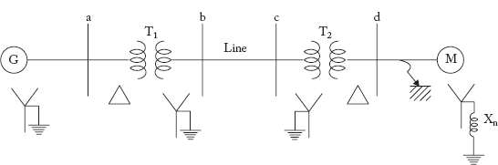
- A single line diagram of a power network is shown in the figure below.
The system data is as given in the table below:

Generator ground reactance is 0.5 p.u.
- draw sequence networks
- find fault currents for a line to line fault on phases B and C at point q. Assume 1.0 p.u. per fault voltage throughout
[GATE 1996 Q.No.14]
- For a fault at the terminals of a synchronous generator, the fault current is maximum for a
- 3-phase fault
- 3-phase to ground fault
- line-to-ground fault
- line-to-line fault
[GATE 1997 Q.No.2]
- For the network shown in figure, the zero sequence reactances in p.u. are indicated. The zero sequence driving point reactance of the node 3 is:
- 0.12
- 0.30
- 0.10
- 0.20
[GATE 1998 Q.No.8]
- The severity of line-to-ground and three-phase faults at the terminals of an unloaded synchronous generator is to be same. If the terminal voltage is 1.0 p.u. and z1 = z2 = j 0.1 p.u., z0 = j0.05 p.u. for the alternator, then the required inductive reactance for neutral grounding is:
- 0.0166 p.u
- 0.05 p.u
- 0.1 p.u
- 0.15 p.u
[GATE 2000 Q.No.10]
- A 50 Hz alternator is rated 500 MVA, 20 kV, with Xd = 1.0 per unit and X″d = 0.2 per unit. It supplies a purely resistive load of 400 MW at 20 kV. The load is connected directly across the generator terminals when a symmetrical fault occurs at the load terminals. The initial rms current in the generator in per unit is generator in per unit is
- 7.22
- 6.4
- 3.22
- 2.2
[GATE 2001 Q.No.7]
- For the Y-bus matrix given in per unit values, where the first, second, third and fourth row refers to bus 1, 2, 3 and 4 respectively, draw the reactance diagram.
[GATE 2001 Q.No.12]
- A single line-to-ground fault occurs on an unloaded generator in phase a positive, negative, and zero sequence impedances of the generator are j0.25 p.u., j0.25 p.u., and j0.15 p.u. respectively. The generator neutral is grounded through a reactance of j0.05 p.u. The prefault generator terminal voltage is 1.0 p.u.
- Draw the positive, negative, and zero sequence networks for the fault given.
- Draw the interconnection of the sequence networks for the fault analysis.
- Determine the fault current.
[GATE 2001 Q.No.5]
- A generator is connected to a transformer which feeds another transformer through a short feeder (see figure). The zero sequence impedance values are expressed in pu on a common base and are indicated in figure. The Thevenin equivalent zero sequence impedance at point B is

- 0.8 + j0.6
- 0.75 + j0.22
- 0.75 + j0.25
- 1.5 + j0.25
[GATE 2002 Q.No.7]
- A 3-phase, 11-kV generator feeds power to a constant power unity power factor load of 100 MW through a 3-phase transmission line. The line-to-line voltage at the terminals of the machine is maintained constant at 11 kV. The per unit positive sequence impedance of the line based on 100 MVA and 11 kV is j0.2. The line-to-line voltage at the load terminals is measured to be less than 11 kV. The total reactive power to be injected at the terminals of the load to increase the line-to-line voltage at the load terminals to 11 kV is
- 100 MVAR
- 10.1 MVAR
- -100 MVAR
- -10.1 MVAR
[GATE 2003 Q.No.10]
- A 20-MVA, 6.6-kV, 3-phase alternator is connected to a 3-phase transmission line. The per unit positive sequence, negative sequence and zero sequence impedances of the alternator are j0.1, and j0.04 respectively. The neutral of the alternator is connected to ground through an inductive reactor of j0.05 p.u. The per unit positive, negative and zero sequence impedances of the transmission line are j0.1 and j0.3 respectively. All per unit values are based on the machine ratings. A solid ground fault occurs at one phase of the far end of the transmission line. The voltage of the alternator neutral with respect to ground during the fault is
- 513.8 V
- 889.9 V
- 1112.0 V
- 642.2 V
[GATE 2003 Q.No.12]
- A three-phase alternator generating unbalanced voltages is connected to an unbalanced load through a 3-phase transmission line as shown in the figure below. The neutral of the alternator and the star point of the load are solidly grounded. The phase voltages of the alternator are
 The positive sequence component of the load current is


[GATE 2003 Q.No.16]
- A 500 MVA, 50 Hz, 3-phase turbo-generator produces power at 22 kV. The Generator is Y-connected and its neutral is solidly grounded. Their sequence reactances are X1 = X2 = 0.15 and X0 = 0.05pu. It is operating at rated voltage and disconnected from the rest of the system (no load). The magnitude of the sub-transient lien current for single line ground fault at the generator terminal in p.u. will be
- 2.851
- 3.333
- 6.667
- 8.553
[GATE 2004 Q.No.13]
- At a 220 kV substation of a power system, it is given that the three-phase fault level is 4000 MVA and single-line to ground fault level is 5000 MVA. Neglecting the resistance and the shunt susceptances of the system,
- The positive sequence driving point reactance at the bus is:
- 2.5 Ω
- 4.033 Ω
- 5.5 Ω
- 12.1 Ω
- And the zero sequence driving point reactance at the bus is:
- 2.2 Ω
- 4.84 Ω
- 18.18 Ω
- 22.72 Ω
[GATE 2005 Q.No.11]
- The positive sequence driving point reactance at the bus is:
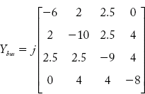
- For a power system the admittance and impedance matrices for the fault studies are as follows.

The pre-fault voltages are 1.0 p.u. at all the buses. The system was unloaded prior to the fault. A solid 3-phase fault takes place at bus 2.
- The post-fault voltages at buses 1 and 3 in per unit respectively are
- 0.24, 0.63
- 0.31, 0.76
- 0.33, 0.67
- 0.67, 0.33
[GATE 2006 Q.No.15]
- The per unit fault feeds from generators connected to buses 1 and 2 respectively are
- 1.20, 2.51
- 1.55, 2.61
- 1.66, 2.50
- 5.00, 2.50
[GATE 2006 Q.No.16]
- The post-fault voltages at buses 1 and 3 in per unit respectively are
- A two machine power system is shown below. Transmission line XY has positive sequence impedance of Z1 Ω and zero sequence impedance of Z0 Ω.
An ‘a’ phase to ground fault with zero fault impedance occurs at the centre of the transmission line. Bus voltage at X and line current from X to F for the ‘a’, are given by Va volts and Ia Amperes, respectively. Then, the impedance measured by the ground distance relay located at the terminal X of line XY will be given by
- Z1/2 Ω
- Z0/2 Ω
- (Z0+Z1)/2 Ω
- Va/Ia Ω

[GATE 2008 Q.No.14]
- Consider a power system shown below:
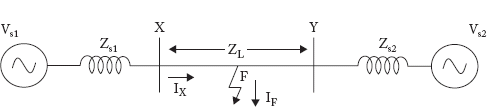
Given that:
Vs1=Vs2=1.0 + j0.0pu;
The positive sequence impedance are Zs1=Zs2=0.001 + j0.01 pu and ZL =0.006 + j0.06pu.
3-phase Base MVA=100
Voltage base = 400 kV (Line to Line)
Nominal system frequency =50 Hz
The reference voltage for phase ‘a’ is defined as v(t)=Vm cos(ωt) .
A symmetrical three-phase fault occurs at centre of the line, i.e. point ‘F’ at time t0.The positive sequence impedance from source S1 to point ‘F’ equals 0.004 + j0.04pu. The waveform corresponding to phase ‘a’ fault current from bus X reveals that decaying dc offset current is negative and in magnitude at its maximum initial value. Assume that the negative sequence impedances are equal to positive sequence impedances, and the zero sequence impedances are three times positive sequence impedances.
- The instant (t0) of the fault will be
- 4.682 ms
- 9.667 ms
- 14.667 ms
- 19.667 ms
[GATE 2008 Q.No.71]
- The rms value of the ac component of fault current (Ix) will be
- 3.59 kA
- 5.07 kA
- 7.18 kA
- 10.15 kA
[GATE 2008 Q.No.72]
- Instead of the three phase fault, if a single line to ground fault occurs on phase ‘a’ at point ‘F’ with zero fault impedance, then the rms value of the ac component of fault current(Ix) for phase ‘a’ will be
- 4.97 p.u
- 7.0 p.u
- 14.93 p.u
- 29.85 p.u
[GATE 2008 Q.No.73]
- The instant (t0) of the fault will be