Chapter 2
Fundamentals of 2D Construction
2-1 Introduction
This chapter demonstrates how to work with AutoCAD commands. You can execute AutoCAD commands by using command tools and a series of prompts. The prompts appear in the command line window and ask the user for a selection or numeric input so that a command sequence can be completed. This chapter uses the Line command to show the various input and prompt sequences that are typical with AutoCAD commands.
Most of the commands contained in the Draw and Modify panels are demonstrated in this chapter. Enough commands are presented for you to be able to create simple 2D shapes. Chapter 3 presents more advanced applications for these commands and introduces some new commands as well.
2-2 Line—Random Points
Use the Line command to draw a straight line between two defined points.
There are four ways to define the length and location of a line:
Randomly select points
Set a specific value for the Snap function and select points with the Snap spacing values
Enter the coordinate values for the starting point and endpoint
Use relative inputs and specify the starting point, the length, and the direction of the line
Randomly Selecting Points
Start a drawing using the acadiso template and select the Line tool on the Draw panel on the Home tab (Figure 2-1).

Figure 2-1
You can also access the Line command by typing the word line or the letter L in response to a command prompt.
The following command sequence appears in the command line window:
Command: _line Specify first point:
Place the cursor anywhere on the drawing screen and press the left mouse button.
AutoCAD responds:
Specify next point or [Undo]:
As you move the cursor from point to point, dynamic input appears on the screen (Figure 2-2). Dynamic input includes an absolute angle box and a length change box. Dynamic input is discussed in Section 2-5.

Figure 2-2
Note
If you do not see dynamic input on the screen, press the F12 function key to turn it on.
Pick another random point on the screen.
AutoCAD responds:
Specify next point or [Undo]:
AutoCAD keeps asking for another point until you press either the Enter key or the right mouse button. When you press the right mouse button (that is, right-click), the right-click menu appears.
Press the right mouse button and click Enter to end the Line command sequence.
You can restart the Line command by pressing the right mouse button immediately after selecting Enter. A right-click menu appears (Figure 2-3). Select Repeat LINE to restart the Line command.

Figure 2-3
Exiting a Command Sequence
If, as you work, you need to exit a command sequence, press the Esc key, and you return to a command prompt. The Esc key allows you to exit almost any AutoCAD command.
Creating a Closed Area
Select the Line tool from the Draw panel.
AutoCAD responds:
Command: _line Specify first point:
Click a random point (such as P1 in Figure 2-4).
Specify next point or [Undo]:

Figure 2-4
Click a second random point.
Specify next point or [Undo]:
Click a third random point.
Specify next point or [Close Undo]:
Type c and then press Enter to activate the Close option.
AutoCAD draws a line from the third point to the starting point, creating a closed area. You can also create an enclosed area by using the Object Snap Endpoint option. As you move the cursor toward a line, a box appears at the line’s endpoint. Clicking within the endpoint box attaches the line to that endpoint. Right-click the Object Snap icon at the bottom of the screen for a list of other Object Snap options.
2-3 Erase
You can erase any line by using the Erase command. There are two ways to erase lines: Select individual lines or use a selection box to choose a group of lines. The Erase tool is located on the Modify panel on the Home tab (Figure 2-5).

Figure 2-5
Erasing Individual Lines
Click the Erase tool on the Modify panel.
The following prompt appears in the command line window:
Command: _erase
Select objects:
The normal crosshairs are replaced by a rectangular selection box called the pickbox. Any time you see the pickbox, AutoCAD expects you to select an entity—in this example, a line.
If you change your mind and do not want to erase anything, select the next command that you want to use, and the Erase command is terminated.
Select the two open lines by placing the rectangular cursor on each line, one at a time, and pressing the left mouse button. The left side of Figure 2-6 shows a single object selected.

Figure 2-6
The lines are highlighted and display grips at their midpoints and endpoints. The highlight indicates that the line has been selected. The selection is confirmed by a change in the prompt:
Select objects: 1 found
Select objects:
Right-click or press the Enter key to complete the Erase sequence.
The two lines disappear from the screen.
Erasing a Group of Lines
Click the Erase tool.
Command: _erase
Select objects:
Place the rectangular select cursor above and to the left of the lines to be erased and click the left mouse button (Figure 2-6). Do not hold the mouse button down.
Move the mouse, and a shaded window drags from the selected first point.
The right side of Figure 2-6 shows a window selection.
When all the lines to be erased are completely within the window, press the left mouse button.
All the lines completely within the window are selected and change to a faint hue. The number of lines selected is indicated in the command line box.
Right-click or press the Enter key to complete the command sequence.
The lines disappear from the screen. You can use the Undo tool to return all the lines, if needed.
If you create the Erase window from right to left, any line even partially within the Erase window is erased. If the left mouse button is held down and dragged across the object, an irregularly shaped window is formed.
2-4 Line—Snap Points
You can draw lines by using calibrated snap spacing. This technique is similar to drawing points randomly, but because the cursor is limited to specific points, the lengths of lines can be determined accurately (Figure 2-7).

Figure 2-7
Drawing Problem
Turn on both the Grid and Snap functions and set both grid spacing and snap spacing to .5. Zoom the grid in or out to fit the screen.
Note
See Section 1-9 for instructions on how to use the Grid and Snap functions.
Select Line from the Draw panel.
Command: _line Specify first point:
Click a grid point.
Specify next point or [Undo]:
Move the cursor horizontally to the right 10 grid spaces and press the left mouse button.
Because the snap spacing has been set to .5, 10 spaces equal 5 units. Watch the dynamic input readings as you move the cursor. The X value should increase by 5, and the Y value should stay the same.
Specify next point or [Undo]:
Move the cursor vertically 6 spaces and press the left mouse button.
Specify next point or [Close Undo]:
Move the cursor horizontally to the left 10 spaces and press the left mouse button.
Specify next point or [Close Undo]:
Type c and press Enter or place the endpoint of the left vertical line on the starting point of the first line. Right-click and select Enter.
You can save or erase the drawing as desired.
2-5 Line—Dynamic Input
Using the Dynamic Input mode allows you to add both angular and distance values to a drawing through the use of screen prompts.
By default, AutoCAD 2023 does not display the Dynamic Input button on the status bar. Use the following steps to turn it on:
Click the Customization button at the right end of the status bar (Figure 2-8).

Figure 2-8
Select Dynamic Input from the pop-up menu to place a check mark next to it and turn it on (Figure 2-9).

Figure 2-9
The Dynamic Input button now appears on the status bar (Figure 2-10).

Figure 2-10
Click anywhere in the drawing area to close the Customization menu.
Dynamic Input mode is enabled when the status bar button is highlighted (Figure 2-10).
Creating Lines Using Dynamic Input
This example was created using inch values.
Click the Line command tool on the Draw panel and select a starting point.
Figure 2-11 shows the dynamic input for the next point.

Figure 2-11
Move the cursor to the approximate location of the second line point.
The distance and angular values for this new point are displayed in dynamic input labels. Do not click the mouse.
Angular values assume that 0
°is a horizontal line to the right of the first line point.
3a Move the cursor to the command line window and type in the desired distance and angle value.
Use the format @Distance<angle. In this example, the input @3.5<45 was entered (Figure 2-12).
Figure 2-12
3b You can also enter the distance and angle for the line by typing the values starting with @. The values appear in the dynamic input boxes on the screen. When the < symbol is entered, a lock icon appears next to the distance value (Figure 2-13). Press Enter when the values are entered.

Figure 2-13
Press Enter.
The angular value is applied to the line, and the dynamic input label prepares for the next line point input.
Complete the desired shape and press Enter.
Accessing Dynamic Input Settings
Use the Drafting Settings dialog box to access dynamic input settings (Figure 2-14).

Figure 2-14
Right-click the Dynamic Input tool at the bottom of the screen and select Dynamic Input Settings.
The Drafting Settings dialog box appears.
The Dynamic Input tab of this dialog box controls the pointer input, dimension input, and dynamic prompts aspects of dynamic input. The default values are used throughout the text.
2-6 Construction Line
The Construction Line (Xline) command is used to draw lines of infinite length. Construction lines are very helpful during the initial layout of a drawing. They can be trimmed as needed during the creation of a drawing.
Note
If you trim a construction line so it now has an endpoint, the remaining part of the construction line becomes a ray. You can create rays directly using the Ray command, which is on the expanded Draw panel.
Select the Construction Line tool from the expanded Draw panel (Figure 2-15).

Figure 2-15
AutoCAD prompts:
Command:_ xline Specify a point or [Hor Ver Ang Bisect Offset]:
Specify a point is the default option.
Note
The Construction Line tool is located on a flyout from the Draw panel. Click the arrow next to the word Draw to access the flyout.
Select or define a starting point.
You can position the direction of the line by moving the cursor or by using dynamic input, as defined in Section 2-5, to define the line’s direction.
Select or use dynamic input to define a through point.
Specify through point:
A line pivots about the designated throughpoint and extends an infinite length in both directions through the cursor. You can position the angle of the line by moving the cursor (Figure 2-16).
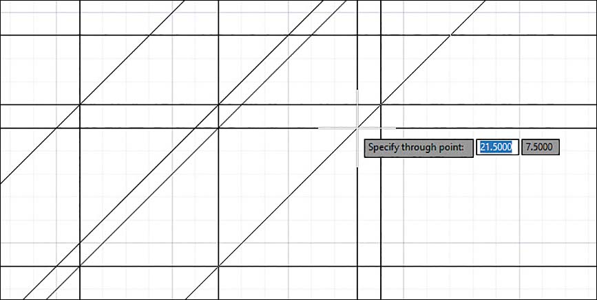
Figure 2-16
Select or define a through point.
An infinitely long line is drawn through the two designated points.
Specify through point:
Press Enter to end the Construction Line command sequence.
You can reactivate the sequence and draw another construction line by pressing the Enter key a second time.
Using Other Construction Line Commands: Hor, Ver, and Ang
The lines shown in Figure 2-16 were created by using the Hor (horizontal), Ver (vertical), and Ang (angular) options. A grid was created, and Snap was turned on so that the lines could be drawn through known points. Figure 2-16 was created as follows:
Set up the drawing screen with grid and snap spacings of .5.
Select Construction Line in the expanded Draw panel.
AutoCAD prompts:
Command:_ xline Specify a point or [Hor Ver Ang Bisect Offset]:
Type H and press Enter.
A horizontal line appears through the cursor.
Specify through point:
Pick or define a point on the drawing screen.
A horizontal line appears through the point. As you move the mouse, another horizontal line appears through the cursor.
Specify through point:
Pick or define a second point.
Specify through point:
Pick or define a third point.
Specify through point:
Right-click, right-click again, and select Repeat XLINE.
Command:_ xline Specify a point or [Hor Ver Ang Bisect Offset]:
Type V and press Enter.
Specify through point:
Draw vertical lines, right-click twice, and select the Repeat XLINE option.
Command:_ xline Specify a point or [Hor Ver Ang Bisect Offset]:
Type A and press Enter.
Enter angle of xline (0) or [Reference]:
Type 45 and press Enter.
Specify through point:
An infinite line at 45
°appears through the crosshairs.Draw 45° lines.
Specify through point:
Press Enter.
Your drawing should look approximately like Figure 2-16.
Using Another Construction Line Option: Offset
The Offset option allows you to draw a construction line parallel to an existing construction line, regardless of the line’s orientation, at a predefined distance (Figure 2-17).

Figure 2-17
Select Construction Line in the expanded Draw panel.
Command:_ xline Specify a point or [Hor Ver Ang Bisect Offset]:
Draw a line approximately 15° to the horizontal.
AutoCAD prompts:
Specify through point:
Double-click the Enter key to restart the Construction Line command sequence.
Command:_ xline Specify a point or [Hor Ver Ang Bisect Offset]:
Type O and press Enter.
The O appears in the dynamic input box.
Offset distance or through <Through>:
Type .5 and press Enter.
Select a line object:
Select the line.
Pick side to offset:
Select a point above the line.
Select a line object:
Select the line just created by the Offset option.
Pick side to offset:
Again select a point above the selected line.
Select a line object:
Draw several more lines below the original line.
Select a line object:
Right-click and select Enter to end the Construction Line Offset sequence and return to the command prompt.
2-7 Circle
The Circle tool button is on the Draw panel. A circle can be defined by a center point and either a radius or a diameter, by two or three points on the diameter, or by the tangents to either two existing lines or arcs and a radius value or to three objects. Each of these command options has a separate tool button on the Draw panel in the Circle tool button’s drop-down (Figure 2-18).
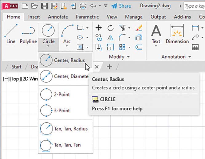
Figure 2-18
Drawing a Circle—Radius
Click Circle on the Draw panel.
Command: _circle Specify a center point for circle or
[3P 2P Ttr (tan tan radius)]
Pick a point or use dynamic input to define a center point.
Specify radius of circle or [Diameter]:
Type 3.50 and press Enter.
The radius value appears in the dynamic input box.
Drawing a Circle—Diameter
Click the down arrow on the Circle tool button and then click Center, Diameter in the drop-down menu.
Command: _circle Specify a center point for circle or
[3P 2P Ttr (tan tan radius)]:
Pick a point or define a center point.
Specify radius of circle or [Diameter]:
Type 8.00 and press Enter.
Drawing a Circle—Two Points
Click the down arrow on the Circle tool button and then click 2-Point in the drop-down menu.
Command: _circle Specify a center point for circle or [3P 2P Ttr
(tan tan radius)]: _2p Specify first end point of circle's diameter:
Select or define a first point.
Select second end point of circle's diameter:
Select or define a second point.
The circle is automatically drawn through the first and second points, as shown on the left side of Figure 2-19.
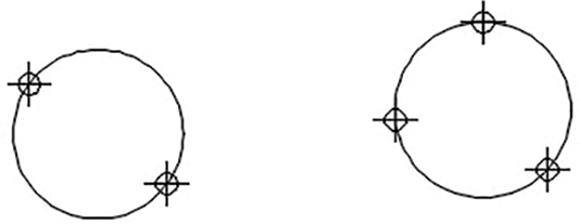
Figure 2-19
Drawing a Circle—Three Points
Click the down arrow on the Circle tool button and then click 3-Point on the drop-down menu.
Command: _circle Specify a center point for circle or
[3P 2P Ttr (tan tan radius)]: _3p Specify first point on circle:
Pick or define a first point.
Specify second point on circle:
Pick or define a second point.
Specify third point on circle:
Pick or define a third point.
The circle is automatically drawn through the three points, as shown on the right side of Figure 2-19.
Drawing a Circle—Tangent Tangent Radius
The tangent tangent radius option allows you to draw a circle tangent to two entities and then specify a radius. Figure 2-20 shows a circle drawn tangent to two lines.

Figure 2-20
Click the down arrow on the Circle tool button and then click Tan, Tan, Radius on the drop-down menu.
Command: _circle Specify a center point for circle or [3P 2P Ttr
(tan tan radius)]: _ttr Specify point on object for first tangent of
circle:
Select an entity.
Specify point on object for second tangent of circle:
Select the other entity.
Specify radius of circle <value>:
Type a radius value and press Enter.
Drawing a circle using the Tan, Tan, Tan option is similar to the steps for Tan, Tan, Radius. Simply select three objects—lines, arcs, or circles—rather than two objects and a radius.
Quadrant-Sensitive Applications
The Circle command’s TTR option is quadrant sensitive—that is, the final location of the tangent circle depends on the location of the tangent spec points. In Figure 2-21, the TTR option was used to draw a large circle tangent to two smaller circles, and in both examples, the larger tangent circle was created by using the same radius. Note the difference in results depending on where on the smaller circles the tangent points were chosen.

Figure 2-21
2-8 Circle Centerline
Standard drawing convention includes centerlines with all circles. Circles usually represent holes. The circle’s center point locates the hole and, during manufacture, serves as the location point for a drill.
Creating Center Marks
Click the Annotate tab on the ribbon.
A new set of ribbon panels appears (Figure 2-22).

Figure 2-22
Click the arrow in the lower-right corner of the Dimensions panel.
The Dimension Style Manager dialog box appears (Figure 2-23).

Figure 2-23
In the Dimension Style Manager dialog box, click Modify.
The Modify Dimension Style: Standard dialog box appears.
Select the Symbols and Arrows tab, then in the Center marks area, click the Line option (Figure 2-24).

Figure 2-24
The preview screen displays centerlines.
Click OK and then Close to return to the drawing screen.
Click the Center Mark tool on the Centerlines panel, and then click the given circle, as shown in Figure 2-25.

Figure 2-25
Centerlines appear on the circle.
2-9 Polyline
A polyline is a linear object made from a series of individual, connected line or arc segments that act as a single entity. Polylines can be used to generate curves and splines and can also be used in three-dimensional applications to produce solid objects.
Drawing a Polyline
Select Polyline from the Draw panel.
AutoCAD prompts:
Command: _pline
Specify start point:
Pick or define a starting point.
Specify next point or [Arc Close Halfwidth Length Undo Width]:
Pick or define a second point.
Specify next point or [Arc Close Halfwidth Length Undo Width]:
Pick or define several more points (Figure 2-26).
Specify next point or [Arc Close Halfwidth Length Undo Width]:
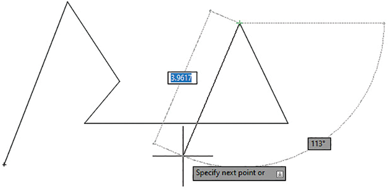
Figure 2-26
Right-click and then select Enter.
Verifying That a Polyline Is a Single Entity
Figure 2-26 shows a polyline.
Select Erase from the Modify panel or enter the word erase.
AutoCAD prompts:
Select objects:
Pick any one of the line segments in the polyline.
Select objects:
The entire polyline, not just the individual line segment, is selected because in AutoCAD, the polyline is a single entity.
Press Enter.
The entire polyline disappears.
Click Undo on the Quick Access Toolbar.
The object reappears.
Drawing a Polyline Arc
Figure 2-27 shows a polyline drawn using the Arc option.

Figure 2-27
Select Polyline from the Draw panel.
AutoCAD prompts:
Specify start point:
Pick or define a starting point.
Specify next point or [Arc Close Halfwidth Length Undo Width]:
Type A and press Enter.
Specify endpoint of arc or [Angle CEnter Direction Halfwidth Line
Radius Second pt Undo Width]:
Pick or define another point.
Specify endpoint of arc or [Angle CEnter Direction Halfwidth Line
Radius Second pt Undo Width]:
Pick or define another point.
Right-click, and then select Enter.
Other Options with a Polyline Arc
Figure 2-28 shows examples of polyline arc options.
Select Polyline from the Draw panel.
Command: _pline
Specify start point:

Figure 2-28
Pick or define a starting point (such as P1 in Figure 2-28).
Specify next point or [Arc Halfwidth Length Undo Width]:
Draw a short horizontal line segment.
Specify next point or [Arc Close Halfwidth Length Undo Width]:
Type A and press Enter.
Specify endpoint of arc or [Angle CEnter CLose Direction Halfwidth Line
Radius Second pt Undo Width]:
Type CE and press Enter.
CE activates the Center option. You can now define an arc that will be part of the polyline by defining the arc’s center point and its angle, chord length, or endpoint.
Specify center point of arc:
Pick or define a center point (such as P2 in Figure 2-28).
Specify endpoint of arc or [Angle Width]:
Pick or define an endpoint (such as P3 in Figure 2-28).
Specify endpoint of arc or [Angle CEnter Direction Halfwidth Line
Radius Second pt Undo Width]:
Type L and press Enter.
The Line option is used to draw straight-line segments.
Specify next point or [Arc Close Halfwidth Length Undo Width]:
Pick or define an endpoint (such as P4 in Figure 2-28).
Specify next point or [Arc Close Halfwidth Length Undo Width]:
Type A and press Enter.
Specify endpoint of arc or [Angle CEnter Direction Halfwidth Line
Radius Second pt Undo Width]:
Type R and press Enter.
Specify radius of arc:
Type 1.5 or another value and press Enter.
Specify endpoint of arc or [Angle]:
Pick or define an endpoint (such as P5 in Figure 2-28).
Specify endpoint of arc or [Angle CEnter CLose Direction Halfwidth
Line Radius Second pt Undo Width]:
Type S and press Enter.
Specify second point on arc:
Pick or define a point (such as P6 in Figure 2-28).
Specify endpoint of arc:
Select or define an endpoint (such as P7 in Figure 2-28).
Specify endpoint of arc or [Angle CEnter CLose Direction Halfwidth
Line Radius Second pt Undo Width]:
Type CL and press Enter.
The CL (close) option joins the last point drawn to the first point of the polyline by use of an arc.
Drawing Different Line Thicknesses
Select Polyline from the Draw panel.
Specify start point:
Select or define a starting point.
Specify next point or [Arc Close Halfwidth Length Undo Width]:
Type W and press Enter.
The Width option defines the width of a line. The Halfwidth option is used to define half of the width of a line.
Specify starting width <0.0000>:
Type 1.00 and press Enter.
Specify ending width <1.0000>:
Press Enter.
Specify next point or [Arc Close Halfwidth Length Undo Width]:
Draw several line segments (Figure 2-29).

Figure 2-29
2-10 Spline
A spline is a non-radial curved line created through (fit spline) or near (control vertex spline) a series of points. If the curve forms an enclosed area, it is called a closed spline. Curved lines that do not enclose an area are called open splines. See Figure 2-30.
Note
There are two ways of drawing splines: using either the Fit or Control Vertex tool buttons on the expanded Draw panel. Fit splines pass through the points you pick onscreen. Control vertex splines are created using inflection points that you pick.

Figure 2-30
Select Spline Fit from the Draw panel. AutoCAD prompts:
Command: _spline

Specify first point or [Method Knots Object]:
Pick or define a starting point.
Specify next point:
Pick or define a second point.
Specify next point or [Close Fit tolerance] <start tangent>:
Select or define two more points.
Specify next point or [Arc Close Halfwidth Length Undo Width]:
Type C and press Enter (Figure 2-30).
2-11 Ellipse
The Ellipse command has two options. These options allow you to define an ellipse by using the lengths of its major and minor axes or by picking a center point and specifying axis lengths. You can also draw elliptical arcs using the third option on the Ellipse tool button.
Drawing an Ellipse—Axis Endpoint
On the Draw panel, click the down arrow next to the Ellipse tool and then click Axis, End.
AutoCAD prompts:
Specify axis endpoint of ellipse or [Arc Center]:
Pick or define a starting point for one of the axes.
Specify other endpoint of axis:
Pick or define an endpoint that defines the length of the axis.
Specify distance to other axis or [Rotation]:
Pick or define a point that defines half of the length of the other axis.
The distance specified in step 4 is the radius of the axis. In the example shown in the extended tooltip (Figure 2-31), points 1 and 2 define the major axes, and point 3 defines the minor axis. The sample ellipse drawn in Figure 2-31 shows an object in which points 1 and 2 were used to define the minor axes, and point 3 was used to define the major axis.

Figure 2-31
Drawing an Ellipse—Center
On the Draw panel, click the down arrow next to the Ellipse tool and then click Center.
AutoCAD prompts:
Specify axis endpoint of ellipse or [Arc Center]:

Specify center of ellipse:
Pick or define the center point of the ellipse (such as P1 in Figure 2-32).
Specify axis endpoint:
Pick or define one of the endpoints of one of the axes (such as P2 in Figure 2-32).

Figure 2-32
The distance between the center point and the endpoint is equal to the radius of the axis.
Specify distance to other axis or [Rotation]:
Pick or define a point that defines half of the length of the other axis (such as P3 in Figure 2-32).
Drawing an Elliptical Arc
On the Draw panel, click the down arrow next to the Ellipse tool button and then click Elliptical Arc.
Specify axis endpoint of elliptical arc or [Center]:
Select or define a point (such as P1 on Figure 2-33).
Specify other endpoint of axis:

Figure 2-33
Select or define a point (such as P2 in Figure 2-33).
The distance between points 1 and 2 defines the length of the major axis.
Specify distance to other axis or [Rotation]:
Select or define a point that defines the minor axis (such as P3 in Figure 2-33).
Specify start angle or [Parameter]:
Type 0 and press Enter.
Specify end angle or [Parameter Included angle]:
Type 315 and press Enter.
2-12 Rectangle
Use the Rectang command to draw rectangular polylines. If you select one of the lines that constitute the rectangle, the entire rectangle is highlighted because it’s a single object. The Explode command, whose tool button is located on the Modify panel, can reduce any block to its individual elements. If a rectangle is exploded, it is changed from a single polyline object to four individual straight lines.
Drawing a Rectangle
Select the Rectangle tool from the Draw panel.
AutoCAD prompts:
Specify first corner point or [Chamfer Elevation Fillet Thickness
Width]:
Pick or define a starting point.
Specify other corner point:
Pick or define a point.
The two points define the length and width of the rectangle. (Figure 2-34).

Figure 2-34
Once you have picked the first corner, you can also choose an option to enter the dimensions, the area, or a non-orthogonal rotation.
Exploding a Rectangle
Select Explode from the Modify panel (Figure 2-35).
Select object:

Figure 2-35
Select the rectangle.
Select object:
Press Enter.
There is no visible change in the rectangle, but it is now composed of four individual straight lines. As a test, use the Erase command to remove one of the lines.
2-13 Polygon
A polygon is a closed polyline object bounded by straight lines. The Polygon command draws only regular polygons, in which all sides and angles are equal. A regular polygon with four equal sides is a square. This example shows how to draw a six-sided polygon, or hexagon.
Drawing a Polygon—Center Point
The Polygon and Rectangle commands share a tool button in the Draw panel. If the tool button shows a rectangle, click the down arrow beside the button and select Polygon.
Select Polygon from the Draw panel (Figure 2-36).
AutoCAD prompts:
Command: _polygon
Enter number of sides <4>:

Figure 2-36
Type 6 and press Enter.
Specify center of polygon or [Edge]:
Select or define a center point.
Enter an option [Inscribed in circle Circumscribed about circle]:
Type C and press Enter.
Specify radius of circle:
Type a value and press Enter.
The Circumscribe option was selected here because the diameter of the designated circle will equal the distance across the flats of the hexagon. The distance across the flats is often used to specify hexagon head bolt sizes and the wrench sizes used to fit them. The Inscribe option creates a polygon where the radius specifies the distance between the corners (see Figure 2-37).

Figure 2-37
Drawing a Polygon—Edge Distance
Select the Polygon tool from the Draw panel.
AutoCAD prompts:
Command: _polygon Enter number of sides <4>:
Type 6 and press Enter.
Specify center of polygon or [Edge]:
Type E and press Enter.
Specify first endpoint of edge:
Pick or define a point.
Specify second endpoint of edge:
Pick or define a point.
2-14 Point
The Point command creates point objects on a drawing. You can set the appearance and size of point objects in the Point Style dialog box. By default, a point object is dimensionless and always appears as a single pixel, regardless of zoom magnification. If you select the Point tool from the Draw menu, you can place multiple point objects until you press Esc to exit the command.
Changing the Shape of a Point
Start with the cursor at the command prompt. Do not click the Point tool.
Type Ptype on the command line and press Enter.
The Point Style dialog box appears, displaying 20 different visual appearances for point objects (Figure 2-38).

Figure 2-38
Click the icon in the middle of the top row and click OK.
On the expanded Draw panel, click Multiple Points and add several points to the screen.
Press the Esc key to exit the Point tool.
Changing the Size of a Point
Type Ptype at a command prompt and press Enter.
In the Point Size edit box, type 2.0 and press Enter.
If you change the point type or point size value, all existing and new point objects take on the new values.
2-15 Text
You can add drawing text with the Multiline Text tool found on the Annotate panel of the Home tab.
Creating Multiline Text
Use the Multiline Text command to enter drawing text. First, define the area in which the text is to be entered. Enter text in the Multiline Text Editor, just as you would with a word processing program. You can move text objects to different locations on the drawing screen by using the Move command.
Select the Multiline Text tool button from the Annotate panel.
AutoCAD prompts:
Specify first corner:
Pick or define a point.
The area that you are about to define is for the entire text entry, but it can be modified. Text can be created with different fonts (Figure 2-39).
Specify opposite corner or [Height Justify Line spacing Rotation Style Width]:

Figure 2-39
Define the other corner of the area.
The Multiline Text Editor window appears in the drawing area, and the Text Editor tab opens at the right end of the ribbon (Figure 2-40).

Figure 2-40
Type in your text and then click the screen outside the text box.
The text will be located on the drawing screen within the specified area.
The Multiline Text Editor
You can use the Multiline Text Editor to change the text height, color, font style, and justification.
Accessing the Multiline Text Editor
The Multiline Text tool is available in the Text panel of the Annotate tab.
Click the Annotate tab.
Click the Multiline Text tool.
Define an area for text.
The Text Editor tab now appears at the end of the ribbon (Figure 2-40).
The Text Editor tab and its panels are not normally visible. It appears only in concert with the Multiline Text command.
Changing Text Height
Click the Multiline Text tool and type the desired text.
Highlight the text in the text editor.
In the Style panel of the Text Editor tab, click and highlight the text height box and type in a new text height (Figure 2-41).

Figure 2-41
Press Enter.
Changing the Text Font
Click the Multiline Text tool and type the desired text.
Highlight the text.
Access the drop-down list of fonts in the Formatting panel of the Text Editor tab by clicking the arrow on the right side of the drop-down and then scroll down the list and select the Times New Roman font.
The font of the selected text changes to Times New Roman (Figure 2-42).
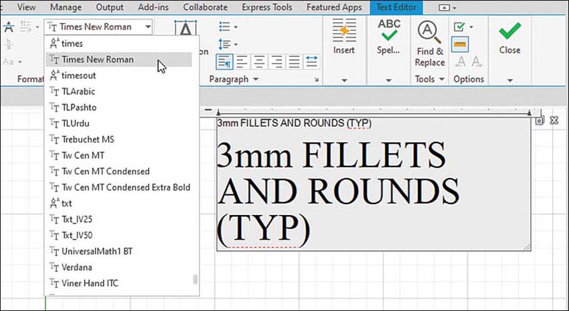
Figure 2-42
Figure 2-42 shows multiple lines of text, one typed in Arial font and the other in Times New Roman font.
Justifying Text
AutoCAD justifies text to the left unless otherwise specified. Figure 2-42 shows text created with the default left justification.
Justifying Text to the Right
In the next steps, the Properties palette is used to change the text justification.
Use a window to select the lines of text shown in Figure 2-42 (that is, select them so that they appear in a selection window).
With the text selected, right-click and select the Properties (not Quick Properties) option.
The Properties palette appears (Figure 2-43).

Figure 2-43
In the Text section of the Properties palette, click the Justify line and then click the arrow on the right side of the box.
Scroll down the drop-down list and click Middle right (Figure 2-43).
The text justifies to the right. Note that the justification is dynamic—that is, as you scroll, the lines of text change.
Figure 2-43 shows a list of other possible justifications available. Figure 2-44 shows examples of the nine possible justifications shown in the drop-down list.

Figure 2-44
Using the Symbol Options
In AutoCAD, you can type some basic characters to display three common symbols used in drawing text:
%%C = Ø (diameter symbol)
%%P = ± (plus/minus symbol)
%%D = ° (degree symbol)
As you type a symbol with one of these options, it begins by appearing just as you type it (in the %% form) in the Multiline Text Editor, but when you type the third character, it changes to the actual symbol.
You can also create these symbols by using the Windows Character chart, as follows:
Alt+0216 = Ø
Alt+0177 = ±
Alt+0176 = °
Changing Text Color
You can change the color of a text object by using the Color option located on the Text Editor tab (Figure 2-45). Click the arrow to the right of the Color box, and a chart of available colors appears.

Figure 2-45
2-16 Move
The Move command relocates selected objects to a new location or locations on a drawing (Figure 2-46).

Figure 2-46
Moving an Object
Select the Move tool button from the Modify panel on the Home tab.
Select objects:
Window the entire object.
Select objects:
Press Enter or right-click.
Specify base point or [Displacement]:
Pick or define a base point.
You can select any point. Snap points are usually used as base points because they can define precise displacement distances and accurate new locations.
Specify second point or <use first point as displacement>:
Pick or define a second point, which is the displacement point (that is, the new location of the objects relative to the base point).
The object moves relative to the first point to its new location, relative to the second point.
2-17 Copy
The Copy command makes an exact duplicate of an existing object. You can use Copy to create more than one copy without reactivating the command. Copy is similar to Move in that you pick a base point and a second point, but Copy leaves the original object.
Copying an Object
Select Copy from the Modify panel.
Select objects:
Window the entire object.
Select objects:
Press Enter or right-click.
Specify base point:
Pick or define a base point.
In the example shown in Figure 2-46, the lower-left corner of the object was selected as the base point.
Specify second point of displacement or <use first point as
displacement>:
Pick or define a second point, which is the displacement point.
The original object remains in its original location, and a new object appears relative to the displacement point (Figure 2-47).

Figure 2-47
Right-click and select Enter to create the copy and end the command.
Making Multiple Copies
AutoCAD continues to make copies of a selected object until all of the copied objects are made.
Make as many copies as you like.
After you make each copy, you see this prompt:
Select a second displacement point:
Move the cursor to a new displacement point or right-click and select Enter to confirm that the objects have been copied (Figure 2-48).

Figure 2-48
2-18 Offset
Select Offset from the Modify panel.
Specify offset distance or [Through Erase Layer] <Through>:
Specify the offset distance by typing a value and then press Enter.
In this example (Figure 2-49), a distance of .25 was selected.
Select object to offset or <exit>:

Figure 2-49
Select an object.
Specify point on side to offset:
Select a point on the side of the object you want to offset.
Select object to offset or <exit>:
You can repeat the process by double-clicking the right mouse button and selecting the Repeat Offset option.
2-19 Mirror
The Mirror command is very useful when drawing symmetrical objects because only half of the object needs be drawn. The second half can be created by using the Mirror command.
Select Mirror from the Modify panel.
Select objects:
Window the object.
Select objects:
Press Enter or right-click.
Specify first point of mirror line:
Select a point on the mirror line.
Specify second point of mirror line:
Select a second point on the mirror line.
Delete source object? [Yes No]<N>:
Press Enter or right-click.
Any line can be used as a mirror line, including lines within an object. Figure 2-50 shows an object mirrored about one of its edge lines.

Figure 2-50
2-20 Array
An array is a group of objects arranged in a regular pattern. You can put objects in arrays using the Rectangular Array, Path Array, and Polar Array commands. Figure 2-51 shows a rectangular array.

Figure 2-51
Using the Rectangular Array Option
Select Rectangular Array from the Modify panel.
Select the object to be arrayed and right-click.
The screen changes. The array creation panels appear on the Array Creation tab (Figure 2-51). The default setting is for a 4-by-3 array. Edit the default array by entering values in the panels on the Array Creation tab. In the example in Figure 2-52, a 5-by-2 array was created.

Figure 2-52
Enter the array values.
Right-click and select the Enter option.
Using the Polar Array Option
With the Polar Array option, objects are arrayed in a circular pattern around a center point (Figure 2-53).

Figure 2-53
Select the Polar Array tool from the Modify panel.
Select the object to be arrayed and right-click.
Specify center point of Array or [Base point Axis of rotation]:
Select a center point for the array.
The screen changes. The array creation panels appear on the Array Creation tab (Figure 2-51). The default setting is for six items in the array. The default array can be edited by using the panels on the Array Creation tab. In this example, eight items were selected, and the Direction tool was activated. Arrayed items can be rotated (the default) or unrotated.
Enter the array values.
Right-click and select the Enter option.
Using the Path Array Option
Use Path Array when you want to create multiple objects along a defined path. The path can be a line, circle, polyline, spline, or any linear or curved object. You can also create 3D path arrays by selecting a helix (see Chapter 3) or a 3D polyline as a path. 3D polylines are not covered in this book.
Select the Path Array tool from the Modify panel.
Select the object to be arrayed and right-click.
Specify center point of Array or [Base point Axis of rotation]:
Select the path object.
Select path curve:
The Array Creation tab appears at the end of the ribbon.
Enter values for the array numbers and distances, and indicate whether the object should be aligned to the path as it is arrayed.
Right-click and select Enter (Figure 2-54).

Figure 2-54
2-21 Rotate
The Rotate command rotates an object about a specified base point (Figure 2-55).

Figure 2-55
By default in AutoCAD, 0° is to the east, or three o’clock on a clock face. Angles in the counterclockwise direction are positive angles.
Rotating an Object
Select Rotate from the Modify panel.
Select objects:
Select the object or objects to be rotated.
Select objects:
Press Enter or right-click.
Specify base point:
Pick or define a base point.
The base point may be anywhere on the screen.
Specify rotation angle or [Reference]:
Type a value and press Enter.
The object rotates about the base point by the specified angle in the counterclockwise direction. To rotate the object in a clockwise direction, enter a negative value.
2-22 Trim
Use the Trim command to remove parts of objects that are crossed by other objects. By default, starting the command selects all objects that can be trimmed. You can hover the cursor over parts of lines or other objects and click to remove them. Trim is a very important AutoCAD command and is used frequently.
Using Trim
Select Trim from the Modify panel.
Select cutting edges:
Select objects:
Move the cursor over a part of any object you want to remove and click when you see the red X over the object.
Press Enter or right-click.
Select object to trim or [Project Edge Undo]:
As shown in Figure 2-56, the left portion of the circle, and the portion of the line within the circle, are deleted.

Figure 2-56
Press Enter.
Selected portions of the objects disappear. Figure 2-57 shows an example similar to the one presented in Figure 2-56, but in this example, different portions of the line and circle are trimmed.

Figure 2-57
2-23 Extend
The Extend command extends selected lines, arcs, or polylines to new borders (Figure 2-58). Extend and Trim work similarly to each other and share a tool button on the Modify panel.

Figure 2-58
Select Extend from the Modify panel.
Select boundary edges:
Select objects:
Move the cursor over a part of any object you want to extend to a new boundary and click when you see the object highlighted and extended (Figure 2-58).
Right-click, and then select Enter.
2-24 Break
Use the Break command to remove portions of an object. It is similar to the Trim command but does not require edges to be cut. Break distances are defined between points (Figure 2-59).

Figure 2-59
Using the Break Command
Select Break from the expanded Modify panel.
Select object:
Select a point on the line.
Selecting the object also sets the first point of the break at the same place. If object snap is enabled and selected points are getting in the way, toggle off the Object Snap button or press F3 to turn off the feature.
Specify second break point or [First point]:
Pick a second point.
The length of the break will be equal to the distance between the two selected points.
Note
Use the Break at Point command to break a line into two parts. It does not remove part of the line but simply breaks the line into two parts.
Using the First Point Option
The F, or First point, option allows you to first select a line and then define the starting point of the break. This means that unlike with the default Break command sequence, as just described, the first selection captures only the line, not the line and the first break point.
Select Break from the Modify panel.
Select object:
Select the line.
Specify second break point or [First point]:
Type F and press Enter.
Specify first break point:
Pick or define the first point of the break. Toggle off Object Snap in the status bar, if necessary.
Specify second break point:
Pick or define the second point of the break.
2-25 Chamfer
A chamfer is a straight-line corner cut, usually cut at 45°. Other angles may be used (Figure 2-60).

Figure 2-60
Creating a Chamfer
The Chamfer and Fillet commands share a tool button on the Modify panel. Click the down arrow next to the button and select the desired command.
Select Chamfer from the Modify panel.
AutoCAD prompts:
(TRIM mode) Current chamfer Dist1 = 0.0000, Dist2 = 0.0000

Select first line or [Polyline Distance Angle Trim Method] <Select
first line>:
Type D and press Enter.
Specify first chamfer distance <0.0000>:
Type .75 and press Enter.
Specify second chamfer distance <0.7500>:
AutoCAD assumes that the chamfer will be at 45
°and automatically sets the second distance equal to the first.Select the first line to be chamfered, then hover the cursor over the second line. The lines and the chamfer are highlighted (Figure 2-60).
Click on the second line to complete the chamfer.
2-26 Fillet
A fillet is a rounded corner (Figure 2-61).
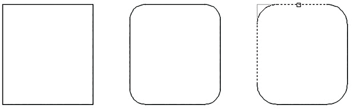
Figure 2-61
Creating a Fillet
Select Fillet from the Modify panel. Click the Fillet/Chamfer tool button if necessary.
Current settings: Mode = Trim, Radius = 0.5000
Select first object or [Polyline Radius Trim]:
Type R and press Enter.
Specify fillet radius <0.0000>:
Type .5 and press Enter.
Command:
Select first object or [Polyline Radius Trim Multiple]:
Select a line.
Select second object:
Hover the cursor over the second line. The lines and the fillet are highlighted.
Click on the second line to complete the fillet.
You can also create fillets between circles (Figure 2-62). The Fillet command is location sensitive, meaning that the location of the selection points will affect the shape of the resulting fillet.

Figure 2-62
2-27 Table
The Table command is used to create tables such as the one shown in Figure 2-63. Tables are used on drawings to define multiple hole dimensions, to define coordinate data, and to create parts lists, among other uses.

Figure 2-63
Creating a Table
Follow the steps below to create a table object:
Click Table on the Annotate panel.
The Insert Table dialog box opens (Figure 2-64).

Figure 2-64
Click the button under Table style at the top of the Insert Table dialog box.
The Table Style dialog box appears (Figure 2-65).

Figure 2-65
Click Modify.
The Modify Table Style: Standard dialog box appears.
Click the Text tab in the Cell styles area (Figure 2-66).

Figure 2-66
The word Data at the top of the Cell styles area indicates that the modifications will be made on the text used in the data cells.
Click the ellipsis button to the right of Text style: Standard (Figure 2-66).
The Text Style dialog box appears (Figure 2-67).

Figure 2-67
Select the Arial font and set the height to 0.25. Then click Apply and Close.
The Modify Table Style: Standard dialog box reappears (Figure 2-66).
Click the arrow to the right of Data under Cell styles and select the Title option.
Confirm that the text height for the Title cells is set to 0.25. Click OK and close the Modify Table Style: Standard and the Table Style dialog boxes.
Return to the Insert Table dialog box and set the number of data rows and columns and the size of boxes; then click OK (Figure 2-68).

Figure 2-68
Note that the number of data rows does not include the column headings. A blank table appears on the screen (Figure 2-69).

Figure 2-69
Click on the appropriate box and type in the required data. Use the arrow keys to move from one box to another and continue entering data.
2-28 Exercise Problems
Redraw the figures that follow. Do not include dimensions in your drawings. Dimension values are as indicated.
EX2-1 Inches

EX2-2 Inches

EX2-3 Millimeters

EX2-4 Millimeters

EX2-5 Inches

EX2-6 Millimeters

EX2-7 Inches

EX2-8 Inches

EX2-9 Millimeters

EX2-10 Inches

EX2-11 Inches

EX2-12 Millimeters

EX2-13 Millimeters

EX2-14 Inches

EX2-15 Millimeters

EX2-16 Millimeters

EX2-17 Inches

EX2-18 Millimeters

EX2-19 Inches

EX2-20 Millimeters

EX2-21 Inches

EX2-22 Millimeters

EX2-23 Millimeters

EX2-24 Inches

EX2-25 Millimeters

EX2-26 Millimeters

EX2-27 Millimeters

EX2-28 Inches

EX2-29 Millimeters

EX2-30 Millimeters

EX2-31 Millimeters

EX2-32 Inches
Redraw the hole plate shown below. Do not include the dimensions on your drawing. Draw and complete the hole table outlined below. Set the text style to Arial. The data text is .18 high, the heading text is .25 high, and the title text is .375 high.


EX2-33 Millimeters
Redraw the hole plate shown below. Do not include the dimensions on your drawing. Draw and complete the hole table outlined below. Set the text style to Arial. The data text is 5 high, the heading text is 10 high, and the title text is 15 high.

