
Chapter 14
Fundamentals of 3D Modeling
14-1 Introduction
This chapter introduces the fundamental concepts needed to produce 3D models in AutoCAD using the 3D Modeling tools with the acad3D and acadiso3D templates. You will make the 3D Modeling workspace current. This workspace presents many additional tools that are absent from the Drawing & Annotation workspace you have used up until now. This chapter also shows how to change viewpoints and how to create, save, and work with user-defined coordinate systems called user coordinate systems, or UCSs.
Note
A workspace is a collection of menus and tools that you use to make relevant settings and select 3D commands. You can access workspaces by using the Quick Access Toolbar or by clicking the Workspace Switching button in the status bar.
This chapter demonstrates how to use both the Model Viewports and Coordinates panels on the Visualize tab of the 3D Modeling ribbon. It also shows how to create orthographic views from given 3D objects by using the View panel tools.
14-2 The World Coordinate System
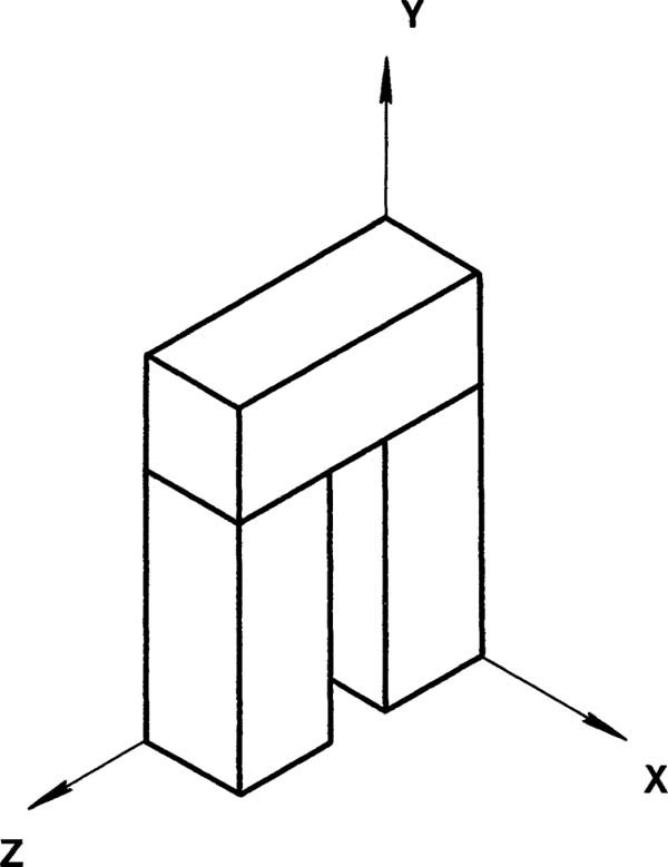
AutoCAD’s absolute coordinate system is called the world coordinate system (WCS). The default setting for the WCS is a viewing position located so that you are looking at the system 90° to its XY plane (Figure 14-1).

Figure 14-1
The Z axis is perpendicular to the XY plane, or directly aligned with your viewpoint. This setup is ideal for 2D drawings and is called a plan view. All of your drawings up to now have been done in this orientation.
Figure 14-2 shows a standard drawing screen created with the acad.dwt template. The display is oriented so that you are looking directly down on the XY plane of the world coordinate system. By default, the XY icon in the lower-left corner of the screen is located at the origin of the WCS. The WCS is a fixed coordinate system and is the basic system of AutoCAD. The User Coordinate System (UCS) is a movable coordinate system. The icon indicating the directions of the X and Y coordinates is called the UCS Icon, and it appears in paper space as well as model space (see Section 12-3).
For purposes of clarity, the background color is set to white.

Figure 14-2
Changing the Background Color to White
With the crosshairs in the drawing area, right-click the mouse.
Click Options.
The Options dialog box appears (Figure 14-3).
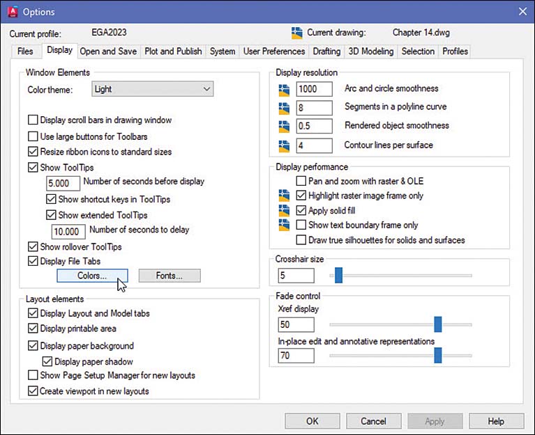
Figure 14-3
Click the Display tab and then click Colors. In the Drawing Window Colors dialog box, click 2D model space, click Uniform background, and set the color to White (Figure 14-4).
The preview box displays the white color.

Figure 14-4
Click Apply & Close, and then click OK to close the Options dialog box.
14-3 Viewpoints
The orientation of the WCS may be changed by changing a drawing’s viewpoint. There are three ways to change the viewpoint:
Type the word view at a command prompt to display the View Manager dialog box.
Manipulate the View Cube located in the upper-right corner of the drawing screen.
Click View Manager on the Named Views panel on the Visualize tab.
The following exercise assumes that the screen displays a grid. The grid serves to help define a visual orientation.
Changing the Viewpoint by Using the View Command
Type the word view at the command prompt and press Enter.
The View Manager dialog box appears (Figure 14-5).
Click Preset Views, select SE Isometric, click Set Current, click Apply, and click OK.

Figure 14-5
The drawing is now oriented as shown in Figure 14-6. Note the change in the crosshairs and the UCS icon; they now display the Z axis. It is important to remember that you are still in the world coordinate system (WCS). The Z axis is always there, but you are looking at it from a different perspective, and it becomes visible in the icon and crosshairs. This concept can be verified by drawing some simple shapes. Figure 14-7 shows a shape created using Line and a circle created using Circle. These shapes are 2D shapes drawn in the WCS.

Figure 14-6

Figure 14-7
Returning to the Original WCS Orientation
To return to the standard 2D plan view of the WCS, click Top on the View Cube (Figure 14-8).

Figure 14-8
The drawing’s orientation returns to the original top view of the XY plane (Figure 14-9).

Figure 14-9
14-4 Perspective and Parallel Grids
Figures 14-10 and 14-11 show a box on a parallel isometric grid background and a box on a perspective grid background. Note the differences in the shape of the box shown against the two backgrounds. The top back corner of the box on the parallel grid appears higher than the same corner of the box on the perspective grid. Parallel grids are generated by selecting one of the preset isometric views listed in the View Manager dialog box (refer to Figure 14-5).

Figure 14-10

Figure 14-11
Perspective grid lines appear to recede to a vanishing point or a series of vanishing points. Parallel grid lines always appear parallel. AutoCAD uses a three-point perspective system. Perspective grids are generated by the acad3D and acadiso3D templates. (See Section 4-12 for an explanation of perspective drawings.)
Creating a Drawing with a Perspective Grid
Click New on the Quick Access Toolbar.
The Select template dialog box appears (Figure 14-12).

Figure 14-12
Select the acadiso3D template and click Open.
Right-click the house-like icon next to the View Cube and select Perspective(Figure 14-13).

Figure 14-13
A perspective grid appears on the screen (Figure 14-14). This template has a default setting of millimeter values. The acad3D template has a default setting of inch values.

Figure 14-14
Figure 14-14 shows two figures drawn using the Line and Circle tools from the Draw panel on the Home tab. Using the Properties panel, their thickness was set to 20 and 50, respectively, to give the figures 3D shapes. Note that the cylinder is centered on the XYZ origin.
Returning to the 2D WCS
Click Top on the View Cube.
Use the mouse wheel to zoom the drawing as necessary.
Figure 14-15 shows the resulting top view. Although the Top view is set, the perspective grid is still active, so the thickened circle no longer appears as a 2D circle. Note that the Z axis does not appear as perpendicular to the XY plane. This is because the shapes are viewed on a perspective grid.

Figure 14-15
Lines on a perspective grid recede to a vanishing point, so they appear closer together as they get farther away from the viewer. When looking down on the shape, the bottom surface appears smaller than the top surface. Note that the top edge of the cylinder has a larger diameter than the base diameter. For this reason, it is better to use 3D parallel projection to create technical shapes in 3D space.
14-5 Setting the 3D Modeling Workspace
Notice the current ribbon tabs. In the Drawing & Annotation workspace that you’ve used up until now, 11 tabs appear by default, from Home to Featured Apps. The panels on these 11 tabs include nearly all the commands you need to create two-dimensional drawings.
Follow these steps to change the current workspace from the 2D setup in the Drafting & Annotation workspace to the 3D Modeling workspace:
On the status bar, click Workspace Switching (the icon looks like a gear wheel).
The menu shown in Figure 14-16 appears.

Figure 14-16
Click 3D Modeling.
The ribbon resets and displays four new panels between Home and Insert:
Solid
Surface
Mesh
Visualize
You can now find the solid modeling tools you use on the panels of the Solid tab. You are also likely to use tools on the Visualize tab, but the Surface and Mesh tabs are not covered in this book.
Accessing the 3D Modeling Mode
Start a new drawing and select an acad3D template.
You see the parallel projection grid shown in Figure 14-17.

Figure 14-17
Click the house-like icon next to the View Cube.
The grid background changes to a 3D parallel grid and is now a 3D workspace. You can verify this by clicking the gear-like icon in the status bar at the bottom of the screen.
In the remainder of this book, you will use the 3D Modeling workspace.
14-6 User Coordinate Systems
A user coordinate system is a coordinate system you define relative to the WCS. Drawings often contain several UCSs, which can be saved and recalled.
AutoCAD drawings can be created only on one plane at a time. So, if you had a box whose bottom surface was drawn on the XY plane of the WCS and you wished to draw a circle on the top surface of the box, you would have to create a new XY plane and a new UCS on the box’s top surface.
This section shows how to create new UCSs. You will draw a solid box and then use it to see how to create and use new UCSs.
Drawing a Solid Box
Create a new drawing by using the acad3D.dwt template, the 3D Modeling workspace, an SE Isometric view orientation, and a parallel grid.
Use the mouse wheel to fit the grid to the screen as needed.
The 3D Modeling workspace is active because you switched to it in Section 14-5. The workspace remains active across sessions until you switch to a different workspace.
Click Box on the Primitive panel of the Solid tab (Figure 14-18).
Command:_box
Specify first corner or [Center]:

Figure 14-18
Type 0,0,0 and press Enter.
Specify other corner or [Cube Length]:
These coordinates locate the box’s corner on the XYZ origin. The corner could, however, be located anywhere on the grid.
Type 5,5,0 or use the Snap tool with dynamic coordinates and press Enter.
Specify height:
Type 2.0 and press Enter.
A box appears on the screen (Figure 14-19). The corner of the box is located on the WCS origin. The Conceptual viewing style is used for this example. You can set the visual style by clicking the Visual Style Controls at the top-left corner of the drawing area and choosing Conceptual from the menu.

Figure 14-19
Clicking the box displays a series of dynamic grips (Figure 14-20). You can change the shape of a box by clicking and dragging any of the arrows or rectangles that appear.
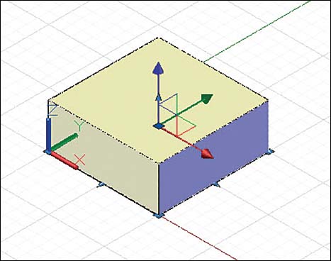
Figure 14-20
Creating a UCS on the Top Surface
Click Origin on the Coordinates panel of the Visualize tab (Figure 14-21). Origin can also be accessed using the Coordinates panel of the Home tab.
Specify new origin point <0,0,0>:

Figure 14-21
Specify the top-left corner of the box as the new origin.
Use Endpoint object snap to define the corner. (It may already be activated. If it isn’t, press Shift and right-click.) The cursor moves only in the XY plane. If you locate the cursor on the corner without using the Endpoint option, the cursor may appear to be on the corner, but, in fact, it is located on the XY plane, at a point behind the corner point.
The origin is now located on the top-left corner of the box. This is a new UCS.
Use the Cylinder tool to draw a cylinder on the top surface of the box. Cylinder is located near the Box tool on the Home tab. Locate the cylinder’s center point at 2.5,2.5,0. Set the diameter to 4.00 and the height to 1.00.
AutoCAD automatically locates the surface’s center point. Click Cylinder and move the cursor onto the top surface. The center point appears.
Saving a UCS
You can save the UCS created in Figure 14-21 and then later restore it without having to redefine it.
Click UCS, Named UCS on the Coordinates panel of the Visualize tab.
The UCS dialog box appears (Figure 14-22), showing the current UCS as Unnamed.

Figure 14-22
Click Unnamed to activate the edit box and enter TopBox.
Click OK.
The UCS is now saved, and the name of the new UCS now appears on the Coordinates panel of the Visualize tab.
Returning to the WCS
Click World on the Coordinates panel of the Visualize tab.
The origin shifts to the original WCS axis (Figure 14-23).

Figure 14-23
Restoring a Saved UCS
Click the Named UCS combo control on the Coordinatespanel, which should currently read World (Figure 14-24).

Figure 14-24
Scroll down and select TopBox.
The TopBox UCS is restored.
Defining a UCS by Selecting Three Points
To use 3 Point to define a UCS on the front right surface of the box, follow these steps:
Click the 3 Point tool on the Coordinates panel of the Visualize tab (Figure 14-25).
Specify new origin point <0,0,0>:

Figure 14-25
Click the lower corner of the box.
This step assumes that Snap is on and set to match the grid. (To turn on Snap, press the F9 key, and to turn on Grid, press F7.) Also, you can use object snap settings to ensure that you are grabbing endpoints. Press Shift and right-click to access the object snap menu.
Specify point on the positive portion of the X-axis <x,x,x>:
Click the far-right lower corner of the box.
Specify point on the positive portion of the Y-axis <x,x,x>:
Use an object snap and pick the upper-front corner of the box, just above the new origin. You must use an object snap because the corner is not on the current XY plane.
Use Endpoint object snap, click the corner, and use the Cylinder command on the Primitive panel to draw a Ø2.00× 1.00 cylinder centered about the 2.5,1,0 point on the new UCS.
Select Cylinder and move the cursor onto the XY plane. Select the center point of the UCS surface (Figure 14-26). The center point can also be defined using coordinate values.

Figure 14-26
Return to the WCS.
14-7 Editing a Solid Model
Solid models can be edited—that is, their shapes can be changed after they have been created. Figure 14-27 shows a view of the 5 × 5 × 2 solid model created in Section 14-6, with the farther left corner at the origin of the WCS.

Figure 14-27
Changing the Size of a Solid Model
Click the box created in Section 14-6.
Blue arrows and grips appear on the base plane of the box (Figure 14-28). You can drag the corner grips to resize the box or drag an arrow to extend one side.

Figure 14-28
Locate the cursor on the 5,5,0 corner of the box and then click and hold the mouse button.
Move the cursor so that the corner has coordinate values 7,7,0. Click the left mouse button.
Using Snap, locate the new corner point or enter the new values for the corner (7,7,0) (Figure 14-29).
Press the Esc key.

Figure 14-29
14-8 Visual Styles
Figure 14-30 shows the same 5 × 5 × 2 solid model from Figure 14-19 drawn on a parallel grid. The box was created using the Box tool from the Primitive panel on the Solid tab and the acad3D template with an SE Isometric view orientation and a Conceptual visual style.

Figure 14-30
Changing Visual Styles
In Section 14-6, you used the Visual Style Controls at the upper-left corner of the drawing area to set the visual style to Conceptual. You can also set the visual style on the Visual Styles panel of the Visualize tab.
On the Visualize tab, click the Visual Styles drop-down on the Visual Styles panel of the Visualize tab and select 2D Wireframe, which is the default option (Figure 14-31).

Figure 14-31
The model changes to the 2D Wireframe visual style.
Figure 14-32 shows the box displaying four of the available styles.

Figure 14-32
14-9 Rotating a UCS Axis
Figure 14-33 shows a 5 × 5 × 2 box drawn on the WCS axis with its origin on the 0,0,0 point. It is displayed in the Conceptual visual style and uses the SW Isometric view orientation.

Figure 14-33
You can create a new UCS by rotating the coordinates about one of the major axes.
Click UCS, X on the Coordinates panel.
Specify rotation axis about the X-axis <90>:
90° is the default value.
Press Enter to accept the default value.
The axis and grid rotate 90° about the X axis. You can now draw on the new XY plane, which has the positive Y axis in the vertical direction. Note the orientation of the background grid (Figure 14-34).

Figure 14-34
Axis rotation can be done dynamically by right-clicking the UCS Icon and selecting an axis. In this example the Y axis is rotated. Click the mouse to select an angle of rotation.
Hover over the UCS Icon and right-click to display the UCS right-click menu. Click Rotate Axis and then click Y.
Specify rotation axis about the Y-axis <90°>:
Press Enter.
The XZ plane and grid rotate 90°. You can now draw on the back plane of the box.
Repeat step 3 to display the UCS right-click menu. Click Rotate Axis and then click Z.
Specify rotation angle about the Z-axis <90°>:
Press Enter.
The axis rotates 90°.
Use Undo to return to the original WCS orientation.
14-10 Drawing Problem
Draw an L-shaped bracket that will be used to demonstrate how to use UCSs.
Start a new drawing using the acad3D template with a parallel grid. Make the SE Isometric view the active view.
Use Box on the Primitive panel and draw a 5 × 5 × 2 box in the Conceptual visual style (Figure 14-35).

Figure 14-35
The UCS Icon is at the origin—0,0,0 in the WCS. You can change the UCS by selecting the UCS Icon and moving it to a different location. In the next steps, you will move the UCS straight up, to the top-left corner of the box.
Click the UCS Icon to display its grips. Pick the grip at the origin and move the icon to the top surface of the box (Figure 14-36). Use Endpoint object snap (by pressing and holding the Shift key and right-clicking) to locate the new origin.

Figure 14-36
Using the new origin, create a box whose base is located from the new origin (0,0,0) to a new corner (2.5,5.0,0). Make the height 2.5 (Figure 14-37).

Figure 14-37
Click the Solid tab and then click Union on the Boolean panel.
Click both boxes.
Return to the WCS.
As shown in Figure 14-38, the Union tool joins the two boxes together to form one object. Notice which lines are removed by the Union tool.

Figure 14-38
14-11 Visual Errors
When working in 3D, it is important to remember that you cannot rely on visual inputs to locate shapes. What you see may be misleading. For example, Figure 14-39, presented using the 3D wireframe visual style, shows a circle that appears to be drawn on the upper-right surface of an L-shaped bracket. In fact, the circle is not located on the surface. This visual distortion is due to the line of sight of the view. The fact that the circle is on the back surface can be verified by changing the object’s orientation.

Figure 14-39
Use the View Cube to look at the bracket from different viewpoints. (Note that the grid has been turned off for clarity.)
Move the mouse over the View Cube.
Hover over the corner at the intersection of the Top, Front, and Right planes.
When the corner is highlighted, press the left mouse button and gently drag to rotate the View Cube and your viewpoint until you can see the true location of the circle.
The new viewpoint is shown in Figure 14-40. This view clearly shows that the circle is drawn on the back surface.

Figure 14-40
14-12 Drawing Problem
Figure 14-41 shows the same L-bracket drawn for Figure 14-38, this time displayed in the 2D Wireframe visual style. This section uses different UCSs to draw 2D shapes on three of the surfaces of the L-bracket.

Figure 14-41
Drawing a Circle on the Upper Front Surface
Use the 3 Point tool on the Coordinates panel and locate the origin and axis system as shown in Figure 14-42.

Figure 14-42
Remember that you can draw on only one plane at a time. Use the object snap options to ensure that the correct origin location is selected.
Draw a circle on the front upper surface, as shown.
In this example, the circle is Ø1.50 and is located on the plane’s center point.
Adding a Rectangle on the Top Surface
Return to the WCS and use the Origin tool on the Coordinates panel to move the axis to the top surface.
Use Rectangle to draw a rectangle on the top surface.
If necessary, turn off the 3D Vertex snap option on the 3D Object Snap tab of the Drafting Settings dialog box.
In this example, a 1 × 3 rectangle is drawn (Figure 14-43).

Figure 14-43
Adding an Ellipse on the Left Vertical Surface
Return to the WCS and use UCS, X on the Coordinates panel to rotate the axis system 90° about the X axis.
As shown in Figure 14-44, the XY axis is now aligned with the left vertical axis.

Figure 14-44
Draw an ellipse on the left vertical surface.
Save the L-bracket.
14-13 Orthographic Views
After a 3D object has been created, orthographic views can be taken directly from the object. The screen is first split into four viewports, each showing the 3D object. The viewpoints of three of the viewports are changed to create the front, top, and right-side views of the object.
For this example, the L-bracket is redrawn, using the same dimensions as presented in Drawing Problem 14-10 but using the acad3D template.
Create four equal viewports by following these steps:
On the Model Viewports panel of the Visualize tab, click Viewport Configuration.
Select the Four: Equal option (Figure 14-45).

Figure 14-45
You can also create model space viewports by using the Viewports dialog box (see Figure 14-46). To create four equal viewports this way, follow these steps:
Type vports at the command prompt.
Select the Four: Equal option.

Figure 14-46
Figure 14-47 shows the L-bracket in four equal viewports. Note that the bold viewport border is a visual reminder that only one viewport can be active at a time. To make a different viewport active, move the cursor into that viewport and click the mouse.

Figure 14-47
Creating Orthographic Views
Move the cursor into the top-left viewport and click the mouse.
This viewport is now the current viewport, and the cursor appears in the viewport.
Click View Control at the top left of the active viewport (it should say SE Isometric) and set the view to TOP (Figure 14-48).

Figure 14-48
A top view of the object appears in the viewport.
Pan and zoom the view as shown in Figure 14-48.
Move the cursor into the lower-left viewport and click the mouse to make this viewport the current viewport.
Use View Controls at the top left of the viewport to set the view to FRONT.
Make the lower-right viewport active and set the view to RIGHT.
Figure 14-49 shows the three orthographic views—TOP, FRONT, and SIDE—as well as the original SE Isometric view in the fourth viewport.

Figure 14-49
14-14 Line Thickness
The Thickness system variable is used to create 3D surfaces from 2D drawing objects. Figure 14-50 shows a line and a circle drawn as normal 2D entities and then drawn a second time with Thickness set for 2 and 3, respectively. The figures are drawn with a 3D parallel grid background. The Line command generates a plane perpendicular to the plane of the original line, and the Circle command generates a cylinder perpendicular to the plane of the base circle.

Figure 14-50
Note
System variables are settings in AutoCAD that govern how specific commands work. For example, Line is the command that draws a straight line segment, whereas Thickness is the system variable that tells AutoCAD how thick the line should be. The Thickness system variable is used with 2D drawing commands like Line, Circle, Arc, Polygon, and so on. System variables are defined in the online help, and you enter them at the command prompt the same way you enter commands.
Using the Thickness Variable
In this example, you will create a new drawing using the acad3D template. Grid and snap spacing are .5, with decimal units, and the viewpoint is SE Isometric.
Type the word thicknessat the command prompt.
Enter new value for THICKNESS <0.0000>:
Type 2 and press Enter.
On the Draw panel of the Home tab, select Line.
Command: _line
From point:
Draw the box shape shown in Figure 14-51.
Right-click and select Enter.

Figure 14-51
The shape shown in the figure is not a box but is four perpendicular surfaces. There is no top or bottom surface.
The default thickness value may also be defined using the Properties palette. Access the Properties palette by windowing the four surfaces, right-clicking the mouse, and selecting Properties. The Properties palette appears (Figure 14-52). Change the thickness value to 3.0000.

Figure 14-52
Figure 14-53 shows a hexagon and an arc drawn with the Thickness setting at values of 2 and 4, respectively.

Figure 14-53
Drawing a Curve with Thickness
Follow these steps to create a curved polyline with thickness:
Start a new drawing using the acad3D template. Select the Conceptual visual style and the SE Isometric view.
Type thickness at the command prompt.
Enter new value for THICKNESS <0.0000>:
Type 3.5 and press Enter.
Select Polyline from the Draw panel.
Command: _pline
Specify start point:
Draw a polyline approximately like the one shown in Figure 14-54.

Figure 14-54
Select Edit Polyline from the Modify panel.
Command: _pedit
Select polyline or [Multiple]:
Select the polyline.
Enter an option [Close Join Width Edit vertex Fit Spline Decurve
Ltype gen Undo]:
Select the Fit option.
Figure 14-55 shows the result.
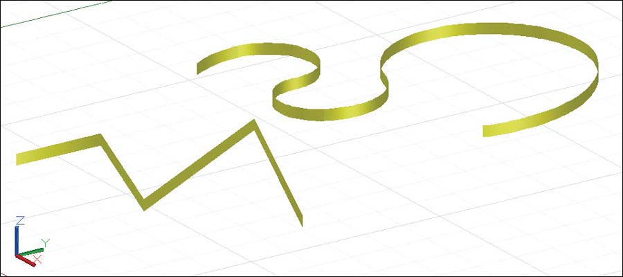
Figure 14-55
Right-click and select Enter.
14-15 Using the Thickness Variable to Create Objects
The Thickness system variable can be used with different UCSs to create simulated 3D objects. The objects are actually open-ended plane structures. The procedure that follows shows how to create the object shown in Figure 14-56. The drawing was created with Grid and Snap set to .5, with decimal units, and with an SE Isometric viewpoint.

Figure 14-56
Drawing the Box
Type the word thickness at the command prompt.
Enter new value for THICKNESS <3.5000>:
Type 6.
Select Line and draw a 10× 10 box like the one shown in Figure 14-57. Place the starting point of the box shape at the origin, 0,0,0.

Figure 14-57
Creating a New UCS
Click the 3 Point UCS tool on the Coordinates panel of the View tab.
Specify new origin point <0,0,0>:
Select the lower-left corner of the box, as shown in Figure 14-58. Use an Endpoint object snap to pick the corner point.
Specify point on the positive portion of X-axis:

Figure 14-58
Click the lower-right corner, as shown.
Specify point on the positive portion of Y-axis:
Pick the corner on the Y axis above the origin.
Drawing the Right Cylinder
This cylinder will be 6 units long, so there is no need to change the thickness setting.
Select Circle and draw a cylinder centered on the right face of the box.
The coordinate value for the cylinder’s center point is 5,3, and the radius value is 2.00 (Figure 14-59).

Figure 14-59
Drawing the Top Cylinder
Return the drawing to the original WCS X,Y axes and then change the location of the XY plane so that the top cylinder can be drawn in the correct position.
Type UCS, press Enter, and press Enter again.
The fastest way to return to the WCS from any UCS is to press Enter twice. The first Enter confirms the command, and the second Enter accepts the default value, which is <World>.
Click Origin on the Coordinatespanel and locate a new origin on the left corner of the top surface of the box.
Type thickness at the command prompt.
Enter new value for THICKNESS <0.0000>:
Type 4 and press Enter.
Select Circle and draw the cylinder as shown in Figure 14-60.
The cylinder’s center point is at 5,5, and its radius is 4.

Figure 14-60
Returning the Drawing to Its Original Settings
Click World on the Coordinates panel.
Type thickness at the command prompt.
Enter new value for THICKNESS <0.0000>:
Type 0 and press Enter.
Turn off the grid.
The object should look like the one shown in Figure 14-61.

Figure 14-61
14-16 Exercise Problems
Exercise Problems EX14-1 through EX14-4 require you to draw 2D shapes on various surfaces of 3D objects created using the Thickness system variable. All 2D shapes should be drawn at the center of the surfaces on which they appear. Either the acad or the acad3D template can be used.
Draw the 2D shapes as shown.
Divide the screen into four viewports and create front, top, and right-side orthographic views for each object.
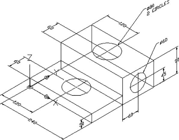
EX14-1 Inches

EX14-2 Millimeters
EX14-3 Millimeters
Both cylinders are centered on the top surfaces as shown.

EX14-4 Millimeters

Redraw the figures presented in Exercise Problems EX14-5 through EX14-17 as wireframe models, using the Thickness variable. Divide the screen into four viewports and create front, top, and right-side orthographic views and one isometric view, as shown earlier in Figure 14-49.
EX14-5 Inches
Box a: X = 6, Y = 5, Z = 2
Box b: X = 4, Y = 4, Z = 4
Box c: X = 5, Y = 2, Z = 1
Hint: Consider a modified version of the NE Isometric viewpoint.

EX14-6 Inches
Box a: X = 8, Y = 8, Z = 1
Box b: X = 6, Y = 6, Z = 2
Box c: X = 2, Y = 2, Z = 6

EX14-7 Millimeters
Each box is 2 × 2 × 5.
EX14-8 Millimeters
Cylinder a: Ø10 × 30 LONG
Cylinder b: Ø20 × 8 LONG
Cylinder c: Ø35 × 18 LONG

EX14-9 Millimeters
EX14-10 Millimeters

EX14-11 Millimeters
Cylinders are 30 LONG.

EX14-12 Millimeters

EX14-13 Millimeters
The Ø12 cylinder is 20 LONG.
The Ø20 cylinder is 12 LONG.

EX14-14 Millimeters

EX14-15 Millimeters

EX14-16 Millimeters
EX14-17 Millimeters
