
Chapter 10
Geometric Tolerances
10-1 Introduction
Geometric tolerancing is a dimensioning and tolerancing system based on the geometric shape of an object. Surfaces may be defined in terms of their flatness or roundness or in terms of how perpendicular or parallel they are to other surfaces (Figure 10-1, right).
Geometric tolerances allow a more exact definition of the shape of an object than do conventional coordinate-type tolerances. Objects can be toleranced in a manner more closely related to their design function or so that their features and surfaces are more directly related to each other.
Figure 10-1 (left) shows a square shape dimensioned and toleranced according to plus and minus tolerances. The resulting tolerance zone has an outside length of 51 square and an inside length of 49 square. The defined tolerance zone allows any shape that falls within it to be deemed acceptable, or correctly manufactured. Figure 10-1 (center) shows an exaggerated shape that fits within the defined tolerance zone and is not square, yet would be acceptable under the specified dimensions and tolerances. Geometric tolerancing can be used to more precisely define the tolerance zone when a more nearly square shape is required.

Figure 10-1
It should be pointed out that geometric tolerancing is not a panacea for all dimensioning and tolerancing problems. In many cases, coordinate tolerancing, as presented in Chapter 9, is sufficient to accurately define an object. Unnecessary or excessive use of geometric tolerances can increase production costs. Most objects are toleranced by using a combination of coordinate and geometric tolerances, depending on the design function of the object.
The key to using tolerances and selecting types of tolerances may be simply stated as, “Decimal points cost money.” Every tolerance should be made as loose as possible while still maintaining the design integrity of the object. If a surface flatness is critical to the correct functioning of the object, then, of course, it will require a very close tolerance. But every tolerance should be considered individually and loosened wherever possible to make the object’s manufacture easier and, therefore, less expensive.
10-2 Tolerances of Form
Tolerances of form are used to define the shape of a surface relative to itself. There are four classifications: flatness, straightness, roundness, and cylindricity. Tolerances of form are not related to other surfaces but apply only to an individual surface.
10-3 Flatness
Flatness tolerances are used to define the amount of variation permitted in an individual surface. The surface is thought of as a plane not related to the rest of the object.
Figure 10-2 shows a rectangular object. How flat is the top surface? The given plus or minus tolerances allow a variation of ±0.5 across the surface. Without additional tolerances, the surface could look like a series of waves that vary between 30.5 and 29.5.
If the example in Figure 10-2 is assigned a flatness tolerance of 0.3, the height of the object, the feature tolerance could continue to vary according to the 30 ± 0.5 tolerance, but the surface itself could not vary by more than 0.3. In the most extreme condition, one end of the surface could be 30.5 above the bottom surface and the other end 29.5, but the surface would still be limited to within two parallel planes 0.3 apart, as shown.
To better understand the meaning of flatness, consider how the surface would be inspected. The surface would be acceptable if a gauge could be moved all around the surface and never varied by more than 0.3 (Figure 10-3). Every point in the plane must be within the specified tolerance.

Figure 10-2

Figure 10-3
10-4 Straightness
Straightness tolerances are used to measure the variation of an individual feature along a straight line in a specified direction. Figure 10-4 shows an object with a straightness tolerance applied to its top surface. Straightness differs from flatness in that straightness measurements are checked by moving a gauge directly across the surface in a single direction. The gauge is not moved randomly about the surface, as is required with flatness.
Straightness tolerances are most often applied to circular or matching objects to help ensure that the parts are not barreled or warped within the given feature tolerance range and therefore not fitted together well. Figure 10-5 shows a cylindrical object dimensioned and toleranced by the use of a standard feature tolerance. The surface of the cylinder may vary within the specified tolerance range, as shown.

Figure 10-4

Figure 10-5
Figure 10-6 shows the same object shown in Figure 10-5, dimensioned and toleranced by use of the same feature tolerance but also including a 0.05 straightness tolerance. The straightness tolerance limits the surface variation to 0.05, as shown.
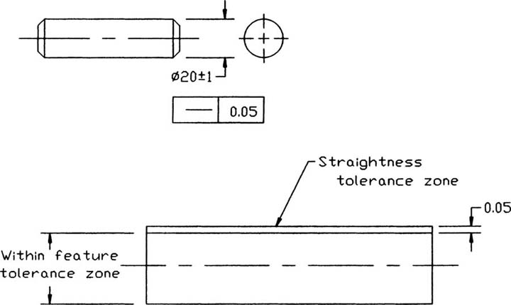
Figure 10-6
10-5 Straightness (RFS and MMC)
Figure 10-7 again shows the same cylinder shown in Figures 10-5 and 10-6. This time, the straightness tolerance is applied about the cylinder’s centerline. This type of tolerance permits the feature tolerance and geometric tolerance to be used together to define a virtual condition. A virtual condition is used to determine the maximum possible size variation of the cylinder or the smallest diameter hole that will always accept the cylinder (see Section 10-17).

Figure 10-7
The geometric tolerance specified in Figure 10-7 is applied to any circular segment along the cylinder, regardless of the cylinder’s diameter. This means that the 0.05 tolerance is applied equally when the cylinder’s diameter measures 19 or when it measures 21. This application is called RFS, which stands for regardless of feature size. RFS conditions are specified in a tolerance either by an S with a circle around it or implied tacitly when no other symbol is used. In Figure 10-7, no symbol is listed after the 0.05 value, so it is assumed to be applied RFS.
Figure 10-8 shows the cylinder dimensioned with an MMC condition applied to the straightness tolerance. MMC stands for maximum material condition and means that the specified straightness tolerance (0.05) is applied only at the MMC condition or when the cylinder is at its maximum diameter size (21).

Figure 10-8
A shaft is an external feature, so its largest possible size, or MMC, occurs when it is at its maximum diameter. A hole is an internal feature. A hole’s MMC condition occurs when it is at its smallest diameter. The MMC condition for holes is discussed later in the chapter, along with positional tolerances.
Applying a straightness tolerance at MMC allows for a variation in the resulting tolerance zone. Because the 0.05 flatness tolerance is applied at MMC, the virtual condition is still 21.05, the same as with the RFS condition; however, the tolerance is applied only at MMC. As the cylinder’s diameter varies within the specified feature tolerance range, the acceptable tolerance zone may vary to maintain the same virtual condition.
Figure 10-8 lists ways in which the tolerance zone varies as the cylinder’s diameter varies. When the cylinder is at its largest size, or MMC, the tolerance zone equals 0.05, or the specified flatness variation. When the cylinder is at its smallest diameter, the tolerance zone equals 2.05, or the total feature size plus the total flatness size. In all variations, the virtual size remains the same, so at any given cylinder diameter value, the size of the tolerance zone can be determined by subtracting the cylinder’s diameter value from the virtual condition.
Figure 10-9 shows a comparison between different methods used to dimension and tolerance a .750 shaft. The first example uses only a feature tolerance. This tolerance sets an upper limit of .755 and a lower limit of .745. Any variations within that range are acceptable.

Figure 10-9
The second example in Figure 10-9 sets a straightness tolerance of .003 about the cylinder’s centerline. No conditions are defined, so the tolerance is applied RFS. This limits the variations in straightness to .003 at all feature sizes. For example, when the shaft is at its smallest possible feature size, .745, the .003 still applies. This means that a shaft measuring .745 that had a straightness variation greater than .003 would be rejected. If the tolerance has been applied at MMC, the part would be accepted. This does not mean that straightness tolerances should always be applied at MMC. If straightness is critical to the design integrity or function of the part, then straightness should be applied in the RFS condition.
The third example in Figure 10-9 applies the straightness tolerance about the centerline at MMC. This tolerance creates a virtual condition of .758. The MMC condition allows the tolerance to vary as the feature tolerance varies, so when the shaft is at its smallest feature size, .745, a straightness tolerance of .013 is acceptable (.010 feature tolerance + .003 straightness tolerance).
If the tolerance specification for the cylinder shown in Figure 10-9 were to have a 0.000 tolerance applied at MMC, it would mean that the shaft would have to be perfectly straight at MMC, or when the shaft was at its maximum value (.755); however, the straightness tolerance could vary as the feature size varied, as discussed for the other tolerance conditions. A 0.000 tolerance means that the MMC and the virtual conditions are equal.
Figure 10-10 shows a very long .750-diameter shaft. Its straightness tolerance includes a length qualifier that serves to limit the straightness variations over each inch of the shaft length and prevents excess waviness over the full length. The tolerance Ø.002/1.000 means that the total straightness may vary over the entire length of the shaft by .003 but that the variation is limited to .002 per 1.000 of shaft length.
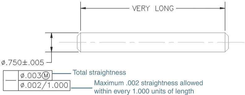
Figure 10-10
10-6 Circularity
Circularity tolerances are used to limit the amount of variation in the roundness of a surface of revolution and are measured at individual cross sections along the length of the object. The measurements are limited to the individual cross sections and are not related to other cross sections. This means that in extreme conditions, the shaft shown in Figure 10-11 could actually taper from a diameter of 21 to a diameter of 19 and never violate the circularity requirement. It also means that qualifications such as MMC could not be applied.
Figure 10-11 shows a shaft that includes a feature tolerance and a circularity tolerance of 0.07. To understand circularity tolerances, consider an individual cross section, or slice, of the cylinder. The shape of the outside edge of the slice varies around the slice. The difference between the maximum diameter and the minimum diameter of the slice can never exceed the stated circularity tolerance.
Circularity tolerances can be applied to tapered sections and spheres, as shown in Figure 10-12. In both applications, circularity is measured around individual cross sections, as it was for the shaft shown in Figure 10-11.

Figure 10-11

Figure 10-12
10-7 Cylindricity
Cylindricity tolerances are used to define a tolerance zone both around individual circular cross sections of an object and also along its length. The resulting tolerance zone looks like two concentric cylinders.
Figure 10-13 shows a shaft that includes a cylindricity tolerance that establishes a tolerance zone of .007. This means that if the maximum measured diameter is determined to be .755, the minimum diameter cannot be less than .748 anywhere on the cylindrical surface. Figure 10-14 shows how to draw the feature control frames that surround the tolerance symbol and size specifications.

Figure 10-13

Figure 10-14
Cylindricity and circularity are somewhat analogous to flatness and straightness. Flatness and cylindricity are concerned with variations across an entire surface or plane. In the case of cylindricity, the plane is shaped like a cylinder. Straightness and circularity are concerned with variations of a single element of a surface—that is, a straight line across the plane in a specified direction for straightness and a path around a single cross section for circularity.
10-8 Creating Geometric Tolerances in AutoCAD
Geometric tolerances are tolerances that limit dimensional variations on the basis of geometric properties of an object. Figure 10-15 shows a list of geometric tolerance symbols. Figure 10-16 shows an object dimensioned by the use of geometric tolerances. The geometric tolerances were created as follows.
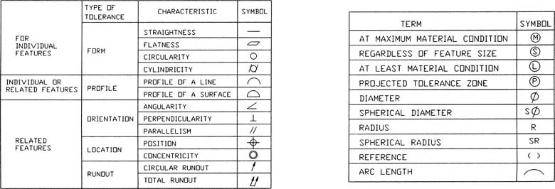
Figure 10-15
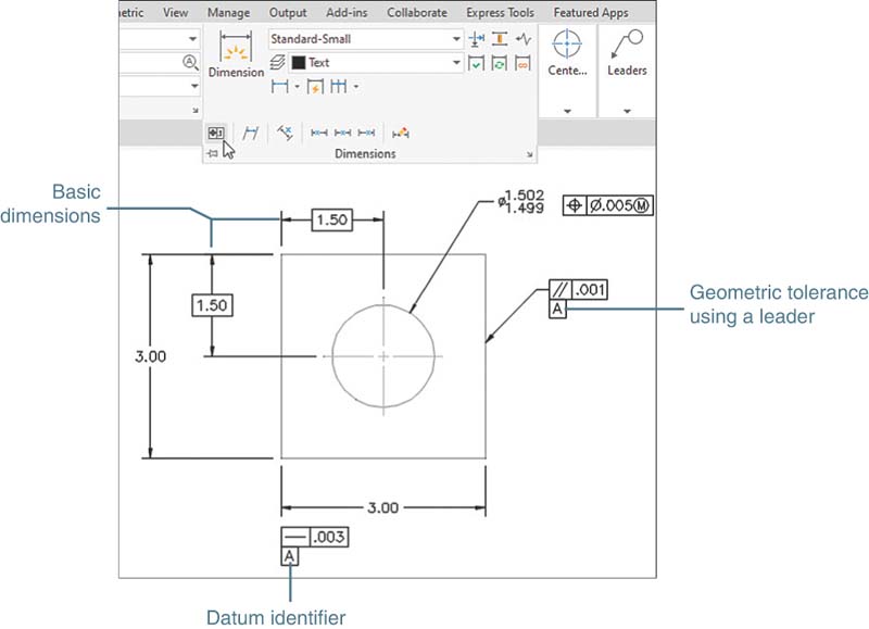
Figure 10-16
Defining a Datum
Select the Tolerance tool from the Dimensions panel.
The Geometric Tolerance dialog box appears (Figure 10-17).

Figure 10-17
Click the Datum Identifier box, and type A, and then click OK.
Command: _tolerance
Enter tolerance location:
Position the datum identifier and press the left mouse button (refer to Figure 10-16).
Defining a Straightness Value
Select the Tolerance tool from the Dimensions panel.
The Geometric Tolerance dialog box appears.
Select the top open box under the heading Sym.
The Symbol dialog box appears (Figure 10-18).

Figure 10-18
Select the straightness symbol and click OK.
The Geometric Tolerance dialog box reappears with the straightness symbol in the first box under the heading Sym.
Click the open Tolerance 1 edit box, type .003, and click OK.
Command: _tolerance
Enter tolerance location:
Position the straightness tolerance as shown in Figure 10-19 and press the left mouse button.
Use Move and Object Snap, if necessary, to reposition the tolerance box (refer to Figure 10-16).

Figure 10-19
Creating a Positional Tolerance
A positional tolerance is used to locate and tolerance a hole in an object. Positional tolerances require base locating dimensions for the hole’s center point. Positional tolerances also require a feature tolerance to define the diameter tolerances of the hole and a geometric tolerance to define the position tolerance for the hole’s center point.
Creating a Basic Dimension
See the two 1.50 dimensions in Figure 10-16 used to locate the center position of the hole.
Access the Dimension Style Manager or type DDIM at a command prompt.
Select Modify.
The Modify Dimension Style: Standard dialog box appears (refer to Figure 9-7).
On the Tolerances tab, select Basic next to the heading Method in the Tolerance format area (Figure 10-20).

Figure 10-20
Click OK, click Close, and return to the drawing screen.
Choose Linear from the Dimensions panel and add the appropriate dimensions.
Refer to Figure 10-16 for examples.
Creating Basic Dimensions from Existing Dimensions
Figure 10-21 shows a shape that includes dimensions. The designer has decided to change two of the dimensions to basic dimensions. The procedure is as follows.

Figure 10-21
Click on the 2.50 dimension.
Grips appear on the dimension.
Right-click and select Properties.
The Properties palette appears (Figure 10-22).
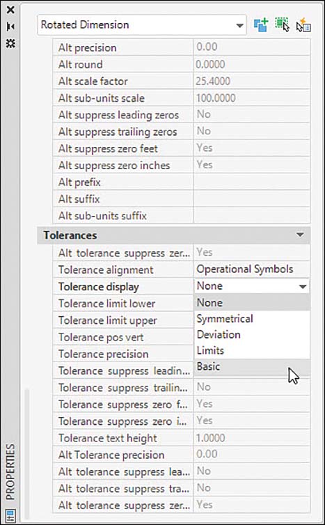
Figure 10-22
Scroll down to the Tolerance settings.
Click next to Tolerance display and select Basic (Figure 10-22).
Scroll down the options and select the Basic option; then click the close X and press the Esc key.
Repeat steps 1–5 for the vertical 1.00 dimension.
Figure 10-23 shows the final result.

Figure 10-23
Adding a Limit Feature Tolerance to a Hole
Access the Dimension Style Manager or type DDIM in response to a command prompt.
Select Modify.
The Modify Dimension Style: Standard dialog box appears.
On the Tolerances tab, select Limits in the Method edit box located in the Tolerance format area (Figure 10-24).

Figure 10-24
Change the upper value to 0.002 by typing in the new value.
Change the lower value to 0.001 by typing in the new value.
Click the arrow to the right of the Precision box in the Tolerance Format area.
Change the precision to three decimal places (0.000).
AutoCAD truncates any input according to the number of decimal places allowed by the precision settings. If the precision settings were two decimal places (0.00), the resulting limit dimensions would both be 1.50. The values defined in the third decimal place would be ignored.
Click OK, click Close, and return to the drawing screen.
Select Diameter on the Dimensions panel.
Select arc or circle:
Select the hole.
Dimension line location (Text Angle):
Locate the diameter dimension.
Adding a Positional Tolerance to the Hole’s Feature Tolerance
Select Tolerance on the Dimensions panel.
The Geometric Tolerance dialog box appears.
Select the top open box under the heading Sym.
The Symbol dialog box appears, with the positional tolerance symbol highlighted (Figure 10-25).

Figure 10-25
Select the top-left edit box under the heading Tolerance 1.
A diameter symbol appears.
Click inside the Value edit box and type 0.0005.
The numbers appear in the box.
Select the top far-right open box under the heading Tolerance 1.
The Material Condition dialog box appears.
Select the maximum material condition (MMC) symbol (the circle with an M in it) (Figure 10-26).

Figure 10-26
Click OK.
Click OK.
Enter tolerance location:
Locate the tolerance box (Figure 10-27).
Use Move to position the box, if necessary.

Figure 10-27
Adding a Geometric Tolerance with a Leader Line
Type qleader at the command prompt.
Specify first leader point, or [Settings] <Settings>:
Select Settings by pressing Enter.
The Leader Settings dialog box appears (Figure 10-28).

Figure 10-28
Select Tolerance in the Annotation Type area and click OK.
Specify first leader point, or [Settings] <Settings>:
Select a starting point for the leader line.
Specify next point:
Draw a short horizontal segment.
The Geometric Tolerance dialog box appears (Figure 10-28).
Select the top Sym box for Tolerance 1.
The Symbol dialog box appears.
Select Parallel.
Select the edit box under the heading Tolerance 1, type 0.0010, and click OK.
10-9 Tolerances of Orientation
Tolerances of orientation are used to relate a feature or surface to another feature or surface. Tolerances of orientation include perpendicularity, parallelism, and angularity. They may be applied under RFS or MMC conditions, but they cannot be applied to individual features by themselves. Defining a surface as parallel to another surface is very much like assigning a flatness value to the surface. The difference is that flatness applies only within the surface; every point on the surface is related to a defined set of limiting parallel planes. Parallelism defines every point in the surface relative to another surface. The two surfaces are therefore directly related to each other, and the condition of one affects the other.
Orientation tolerances are used with locational tolerances. A feature is first located, and then it is oriented within the locational tolerances. This means that the orientation tolerance must always be less than the locational tolerances. The next four sections further explain this requirement.
10-10 Datums
A datum is a point, an axis, or a surface that is used as a starting reference point for dimensions and tolerances. Figure 10-29 shows a rectangular object with three datum planes labeled A, B, and C. The three datum planes are called the primary, secondary, and tertiary datums, respectively. The three datum planes are, by definition, oriented exactly 90° to one another. A datum surface is defined by placing a filled datum triangle at the end of a leader line.

Figure 10-29
Figure 10-30 shows the A datum symbol. Create it as follows.

Figure 10-30
Access the Multileader Style Manager by clicking the arrowhead in the lower-right corner of the Leaders panel under the Annotate tab.
Click New to create a new multileader style. Name it Datum and click Continue.
On the Leader Format tab, in the Arrowhead area, click the down arrow next to Symbol. Scroll down the symbols options and select Datum triangle filled.
Click OK and then click Close.
Note
In step 3, either Datum triangle filled or Datum triangle is acceptable.
Datum planes are assumed to be perfectly flat. When assigning a datum status to a surface, be sure that the surface is reasonably flat. This means that datum surfaces should be toleranced by using surface finishes or created by using machine techniques that produce flat surfaces.
10-11 Perpendicularity
Perpendicularity tolerances are used to limit the amount of variation for a surface or feature within two planes perpendicular to a specified datum. Figure 10-31 shows a rectangular object. The bottom surface is assigned as datum A, and the right vertical edge is toleranced so that it must be perpendicular within a limit of 0.05 to datum A. The perpendicularity tolerance defines a tolerance zone 0.05 wide between two parallel planes that are perpendicular to datum A.

Figure 10-31
The object also includes a horizontal dimension and tolerance of 40 ± 1. This tolerance is called a locational tolerance because it serves to locate the right edge of the object. As with rectangular tolerances discussed in Chapter 9, the 40 ± 1 controls the location of the edge—that is, how far away or how close it can be to the left edge—but does not directly control the shape of the edge. Any shape that falls within the specified tolerance range is acceptable. This may, in fact, be sufficient for a given design, but if a more controlled shape is required, a perpendicularity tolerance must be added. The perpendicularity tolerance works within the locational tolerance to ensure that the edge is not only within the locational tolerance but also is perpendicular to datum A.
Figure 10-31 shows the two extreme conditions for the 40 ± 1 locational tolerance. The perpendicularity tolerance is applied by first measuring the surface and determining its maximum and minimum lengths. The difference between these two measurements must be less than 0.05. Thus, if the measured maximum distance is 41, then no other part of the surface may be less than 41 – 0.05 = 40.95.
Tolerances of perpendicularity serve to complement locational tolerances, to make the shape more exact, so that tolerances of perpendicularity must always be smaller than tolerances of location. It would be of little use, for example, to assign a perpendicularity tolerance of 1.5 for the object shown in Figure 10-31. The locational tolerance would prevent the variation from ever reaching the limits specified by such a large perpendicularity tolerance.
Figure 10-32 shows a perpendicularity tolerance applied to cylindrical features: a shaft and a hole. The figure includes examples of both RFS and MMC applications. As with straightness tolerances applied at MMC, perpendicularity tolerances applied about a hole or shaft’s centerline allow the tolerance zone to vary as the feature size varies.
The inclusion of the Ø symbol in a geometric tolerance is critical to its interpretation (Figure 10-33). If the Ø symbol is not included, the tolerance applies only to the view in which it is written. This means that the tolerance zone is shaped like a rectangular slice, not a cylinder, as would be the case if the Ø symbol were included. In general, it is better always to include the Ø symbol for cylindrical features because it generates a tolerance zone more like that used in positional tolerancing.

Figure 10-32

Figure 10-33
Figure 10-34 shows a perpendicularity tolerance applied to a slot, which is a noncylindrical feature. The MMC specification is for variations in the tolerance zone.
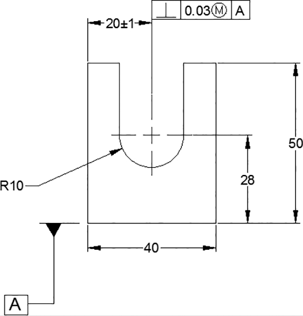
Figure 10-34
10-12 Parallelism
Parallelism is used to ensure that all points within a plane are within two parallel planes that are parallel to a referenced datum plane. Figure 10-35 shows a rectangular object that is toleranced so that its top surface is parallel to the bottom surface within 0.02. This means that every point on the top surface must be within a set of parallel planes 0.02 apart. These parallel tolerancing planes are located by determining the maximum and minimum distances from the datum surface. The difference between the maximum and minimum values may not exceed the stated 0.02 tolerance.

Figure 10-35
In the extreme condition of maximum feature size, the top surface is located 40.5 above the datum plane. The parallelism tolerance is then applied, meaning that no point on the surface may be closer than 40.3 to the datum. This is an RFS condition. The MMC condition may also be applied, thereby allowing the tolerance zone to vary as the feature size varies.
10-13 Angularism
Angularism tolerances are used to limit the variance of surfaces and axes that are at an angle relative to a datum. Angularism tolerances are applied, like perpendicularity and parallelism tolerances, as a way to better control the shape of locational tolerances.
Figure 10-36 shows an angularism tolerance and several ways in which it is interpreted at extreme conditions.

Figure 10-36
10-14 Profiles
Profile tolerances are used to limit the variations of irregular surfaces. They may be assigned as either bilateral or unilateral tolerances. There are two types of profile tolerances: surface and line. Surface profile tolerances limit the variation of an entire surface, whereas a line profile tolerance limits the variations along a single line across a surface.
Figure 10-37 shows an object that includes a surface profile tolerance referenced to an irregular surface. The tolerance is considered a bilateral tolerance because no other specification is given. This means that all points on the surface must be located between two parallel planes 0.08 apart that are centered about the irregular surface. The measurements are taken perpendicular to the surface.

Figure 10-37
Unilateral applications of surface profile tolerances must be indicated on the drawing via phantom lines. A phantom line indicates on which side of the true profile line of the irregular surface the tolerance is to be applied. A phantom line above the irregular surface indicates that the tolerance is to be applied by making the true profile line 0 and then adding a specified tolerance range above that line (Figures 10-38 and 10-39).


Figure 10-38
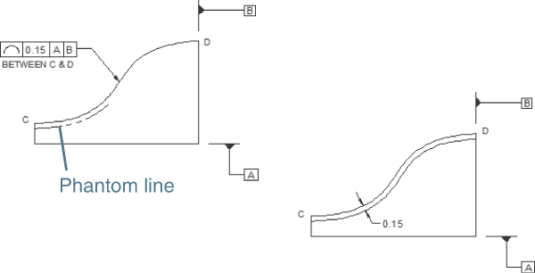
Figure 10-39
Profiles of line tolerances are applied to irregular surfaces, as shown in Figure 10-38. Profiles of line tolerances are particularly helpful for tolerancing an irregular surface that is constantly changing, such as the surface of an airplane wing.
Surface and line profile tolerances are somewhat analogous to flatness and straightness tolerances. Flatness and surface profile tolerances are applied across an entire surface; straightness and line profile tolerances are applied only along a single line across the surface.
10-15 Runouts
A runout tolerance is used to limit the variations between features of an object and a datum. More specifically, runout tolerances are applied to surfaces around a datum axis such as a cylinder or to a surface constructed perpendicular to a datum axis. There are two types of runout tolerances: circular and total.
Figure 10-40 shows a cylinder that includes a circular runout tolerance. The runout requirements are checked by rotating the object about its longitudinal axis or datum axis while holding an indicator gauge in a fixed position on the surface of the object.


Figure 10-40
Runout tolerances may be either bilateral or unilateral. A runout tolerance is assumed to be bilateral unless otherwise indicated. If a runout tolerance is to be unilateral, a phantom line is used to indicate to which side of the object’s true surface the tolerance is to be applied (Figure 10-41).
Runout tolerances may be applied to tapered areas of cylindrical objects, as shown in Figure 10-42. The tolerance is checked by rotating the object about a datum axis while holding an indicator gauge in place.

Figure 10-41
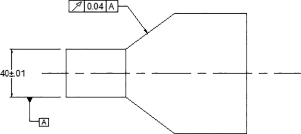
Figure 10-42
A total runout tolerance limits the variation across an entire surface (Figure 10-43). An indicator gauge is not held in place while the object is rotated, as it is for circular runout tolerances, but is moved about the rotating surface.


Figure 10-43
Figure 10-44 shows a circular runout tolerance that references two datums. The two datums serve as one datum. The object can be rotated about both datums simultaneously as the runout tolerances are checked.

Figure 10-44
10-16 Positional Tolerances
Positional tolerances are used to locate and tolerance holes. Positional tolerances create a circular tolerance zone for hole center point locations that differs from the rectangular-shaped tolerance zone created by linear coordinate dimensions (Figure 10-45).
The circular tolerance zone allows for an increase in acceptable tolerance variation without compromising the design integrity of the object. Note that some of the possible hole center points fall in an area outside the rectangular tolerance zone but are still within the circular tolerance zone.
If the hole had been located according to linear coordinate dimensions, center points located beyond the rectangular tolerance zone would have been rejected as being beyond tolerance, and yet holes produced according to these locations would function correctly, from a design standpoint. The center point locations would be acceptable if positional tolerances had been specified. The finished hole is round, so a round tolerance zone is appropriate. The rectangular tolerance zone rejects some holes unnecessarily.
Holes are dimensioned and toleranced by the use of geometric tolerances with a combination of locating dimensions, feature dimensions and tolerances, and positional tolerances (Figure 10-46). The locating dimensions, which are enclosed in rectangular boxes, are called basic dimensions. Basic dimensions are assumed to be exact.
The feature tolerances for the hole are as presented in Chapter 9. They can be presented by using plus or minus, or limit-type, tolerances. In the example shown in Figure 10-46, the diameter of the hole is toleranced by a ±0.05 tolerance.
The basic locating dimensions of 45 and 50 are assumed to be exact. The tolerances that would normally accompany linear locational dimensions are replaced by the positional tolerance. The positional tolerance also specifies that the tolerance be applied at the centerline at maximum material condition. The resulting tolerance zones are as shown in Figure 10-46.

Figure 10-45
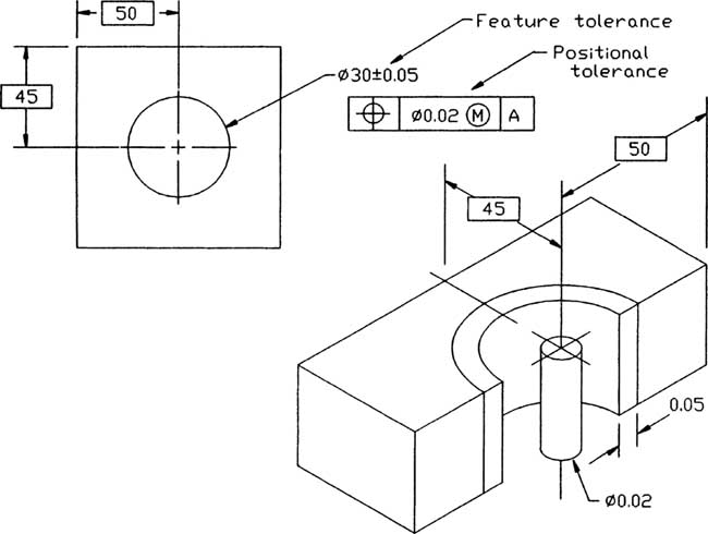
Figure 10-46
Figure 10-47 shows an object containing two holes that are dimensioned and toleranced by using positional tolerances. There are two consecutive horizontal basic dimensions. Because basic dimensions are exact, they do not have tolerances that accumulate; that is, there is no tolerance buildup.
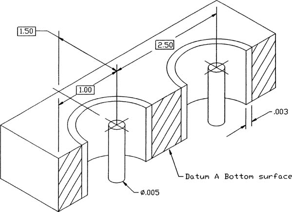

Figure 10-47
10-17 Virtual Condition
Virtual condition is a combination of a feature’s MMC and its geometric tolerance. For external features (shafts), it is the MMC plus the geometric tolerance; for internal features (holes), it is the MMC minus the geometric tolerance.
The following calculations are based on the dimensions shown in Figure 10-48. (The symbol –A– is an older datum plane symbol.)

Figure 10-48
Calculating the Virtual Condition for a Shaft
25.5 MMC for shaft—maximum diameter
+0.3 Geometric tolerance
25.8 Virtual condition
Calculating the Virtual Condition for a Hole
24.5 MMC for hole—minimum diameter
–0.3 Geometric tolerance
24.2 Virtual condition
10-18 Floating Fasteners
Positional tolerances are particularly helpful when dimensioning matching parts. Because basic locating dimensions are considered exact, the sizing of mating parts is dependent only on the MMC of the hole and shaft and the geometric tolerance between them.
The relationship for floating fasteners and holes in objects may be expressed as the formula
H – T = F
where
H = Hole at MMC
T = Geometric tolerance
F = Shaft at MMC
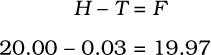
A floating fastener is a fastener that is free to move in either object. It is not attached to either object, and it does not screw into either object. Figure 10-49 shows two objects that are to be joined by a common floating shaft, such as a bolt or screw. The feature size and tolerance and the positional geometric tolerance are both given. The minimum size hole that will always just fit is determined by the following formula:
H – T = F
11.97 – 0.02 = 11.95
Therefore, the shaft’s diameter at MMC, the shaft’s maximum diameter, equals 11.95. Any required tolerance would have to be subtracted from this shaft size.
The 0.02 geometric tolerance is applied at the hole’s MMC. Thus, as the hole’s size expands within its feature tolerance, the tolerance zone for the acceptable matching parts also expands (see the table in Figure 10-49).

Figure 10-49
10-19 Drawing Problem
The situation presented in Figure 10-49 can be worked in reverse; that is, hole sizes can be derived from given shaft sizes.
The two objects shown in Figure 10-50 are to be joined by a .250-inch bolt. The parts are floating; that is, they are both free to move, and the fastener is not joined to either object. What is the MMC of the holes if the positional tolerance is to be .030?
A manufacturer’s catalog specifies that the tolerance for a .250 bolt is .2500 to .2600.
Rewriting the formula
H – T = F
to isolate the H, we have
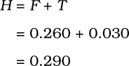
The 0.290 value represents the minimum hole diameter, MMC, for all four holes, that will always accept the 0.250 bolt. Figure 10-51 shows the resulting drawing callout.
Any clearance requirements or tolerances for the hole would have to be added to the 0.290 value.
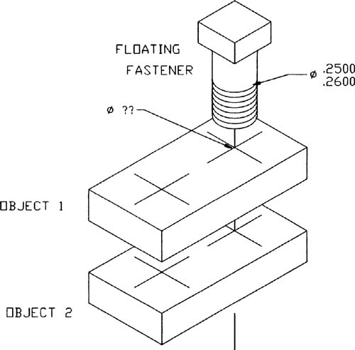
Figure 10-50

Figure 10-51
10-20 Drawing Problem
Repeat the problem presented in Drawing Problem 10-19 but be sure that there is always a minimum clearance of .002 between the hole and the shaft and assign a hole tolerance of .0010.
Drawing Problem 10-19 determined that the maximum hole diameter that would always accept the .250 bolt was .290, according to the .030 positional tolerance. If the minimum clearance is to be .002, the maximum hole diameter is found as follows:
.290 | Minimum hole diameter that will always accept the bolt (0 clearance at MMC) |
+.002 | Minimum clearance |
.292 | Minimum hole diameter including clearance |
Now assign the tolerance to the hole:
.292 | Minimum hole diameter |
+.001 | Tolerance |
.293 | Minimum hole diameter |
Figure 10-52 shows the appropriate drawing callout. The choice of clearance size and hole tolerance varies with the design requirements for the objects.

Figure 10-52
10-21 Fixed Fasteners
A fixed fastener is a fastener that is attached to one of the mating objects (Figure 10-53). Because the fastener is fixed to one of the objects, the geometric tolerance zone must be smaller than that used for floating fasteners. The fixed fastener cannot move without moving the object to which it is attached. The relationship between fixed fasteners and holes in mating objects is defined by the following formula:
H – 2T = F

Figure 10-53
The tolerance zone is cut in half, as can be demonstrated by the objects shown in Figure 10-54. The same feature sizes that were used in Figure 10-49 are assigned, but in this example, the fasteners are fixed. Solving for the geometric tolerance, we obtain the following value:


Figure 10-54
The resulting positional tolerance is half that obtained for floating fasteners.
10-22 Drawing Problem
This problem is similar to Drawing Problem 10-19, but the given conditions are applied to fixed fasteners rather than to floating fasteners. Compare the resulting shaft diameters for the two problems (Figure 10-55).
What is the minimum-diameter hole that will always accept the fixed fasteners?
If the minimum clearance is .005 and the hole is to have a tolerance of .002, what are the maximum and minimum diameters of the hole?

If the minimum clearance is .005 and the hole tolerance is .002,
.320 | Virtual condition |
+.005 | Clearance |
.325 | Minimum hole diameter |
+.002 | Tolerance |
.327 | Maximum hole diameter |
The maximum and minimum values for the hole’s diameter can then be added to the drawing of the object that fits over the fixed fasteners (Figure 10-56).
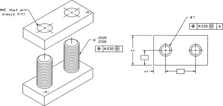
Figure 10-55

Figure 10-56
10-23 Design Problems
This problem was originally done in Section 9-27 using rectangular tolerances. It is done in this section using positional geometric tolerances so that the two systems can be compared. It is suggested that you review Section 9-27 before reading this section.
Figure 10-57 shows top and bottom parts that are to be joined in the floating condition. A nominal distance of 50 between hole centers and 20 for the holes has been assigned. In Section 9-27, a rectangular tolerance of ±0.01 was selected, and there was a minimum hole diameter of 20.00. Figure 10-58 shows the resulting tolerance zones.

Figure 10-57


Figure 10-58
The diagonal distance across the rectangular tolerance zone is .028 and was rounded to .03 to yield a maximum possible fastener diameter of 19.97. If the same .03 value is used to calculate the fastener diameter by using positional tolerance, the results are as follows:
The results seem to be the same, but because of the circular shape of the positional tolerance zone, the manufactured results are not the same. The minimum distance between the inside edges of the rectangular zones is 49.98, or .01 from the center point of each hole. The minimum distance from the innermost points of the circular tolerance zones is 49.97, or .015 (half of the rounded .03 value) from the center point of each hole.
The same value difference also occurs for the maximum distance between center points, where 50.02 is the maximum distance for the rectangular tolerances and 50.03 is the maximum distance for the circular tolerances. The size of the circular tolerance zone increased more because the hole tolerances are assigned at MMC. Figure 10-58 shows a comparison between the tolerance zones, and Figure 10-59 shows how the positional tolerances would be presented on a drawing of either the top or bottom part.
Figure 10-60 shows the same top and bottom parts joined together in the fixed condition. The initial nominal values are the same. If the same .03 diagonal value is assigned as a positional tolerance, the results are as follows:
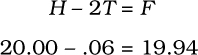
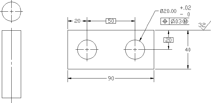
Figure 10-59

Figure 10-60
These results appear to be the same as those generated by the rectangular tolerance zone, but the circular tolerance zone allows a greater variance in acceptable manufactured parts. Figure 10-61 shows how the positional tolerance would be presented on a drawing.
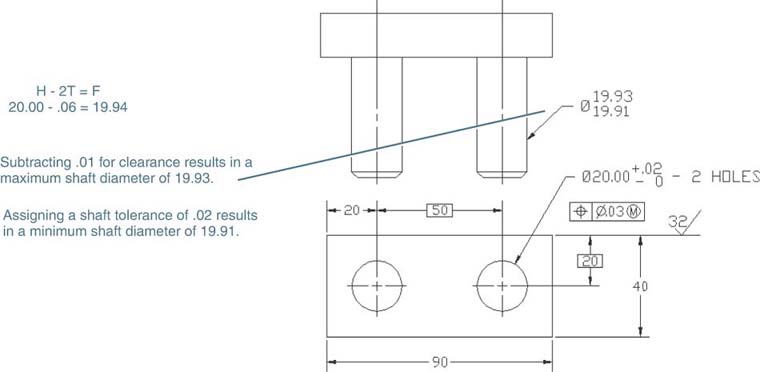
Figure 10-61
10-24 Exercise Problems
EX10-1
Redraw the object shown. Include all dimensions and tolerances.

EX10-2
Redraw the following shaft and add a feature dimension and tolerance of 36 ± 0.1 and a straightness tolerance of 0.07 about the centerline at MMC.

EX10-3
Given the shaft shown, what is the minimum hole diameter that will always accept the shaft?
If the minimum clearance between the shaft and a hole is equal to 0.02 and the tolerance on the hole is to be 0.6, what are the maximum and minimum diameters for the hole?

EX10-4
Given the shaft shown, what is the minimum hole diameter that will always accept the shaft?
If the minimum clearance between the shaft and a hole is equal to .005 and the tolerance on the hole is to be .007, what are the maximum and minimum diameters for the hole?

EX10-5
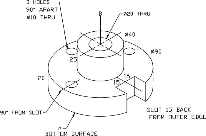
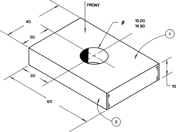
Draw front and right-side views of the object shown and add the appropriate dimensions and tolerances on the basis of the information that follows. Numbers located next to an edge line indicate the length of the edge.
Define surfaces A, B, and C as primary, secondary, and tertiary datums, respectively.
Assign a tolerance of ±0.5 to all linear dimensions.
Assign a feature tolerance of 12.07 – 12.00 to the protruding shaft.
Assign a flatness tolerance of 0.01 to surface A.
Assign a straightness tolerance of 0.03 to the protruding shaft.
Assign a perpendicularity tolerance of 0.02 to the centerline of the protruding shaft at MMC relative to datum A.

EX10-6
Draw front and right-side views of the object shown, and add the following dimensions and tolerances:
Define the bottom surface as datum A.
Assign a perpendicularity tolerance of 0.4 to both sides of the slot relative to datum A.
Assign a perpendicularity tolerance of 0.2 to the centerline of the 30-diameter hole centerline at MMC relative to datum A.
Assign a feature tolerance of ±0.8 to all three holes.
Assign a parallelism tolerance of 0.2 to the common centerline between the two 20-diameter holes relative to datum A.
Assign a tolerance of ±0.5 to all linear dimensions.

EX10-7
Draw a circular front and the appropriate right-side view of the object shown and add the following dimensions and tolerances:
Assign datum A as indicated.
Assign the object’s longitudinal axis as datum B.
Assign the object’s centerline through the slot as datum C.
Assign a tolerance of ±0.5 to all linear tolerances.
Assign a tolerance of ±0.5 to all circular-shaped features.
Assign a parallelism tolerance of 0.01 to both edges of the slot.
Assign a perpendicularity tolerance of 0.01 to the outside edge of the protruding shaft.
EX10-8
Given the two objects shown, draw a front view and a side view of each. Assign a tolerance of ±0.5 to all linear dimensions. Assign a feature tolerance of ±0.4 to the shaft and also assign a straightness tolerance of 0.2 to the shaft’s centerline at MMC.
Tolerance the hole so that it will always accept the shaft with a minimum clearance of 0.1 and a feature tolerance of 0.2. Assign a perpendicularity tolerance of 0.05 to the centerline of the hole at MMC.

EX10-9
Given the two objects shown, draw a front view and a side view of each. Assign a tolerance of ±.005 to all linear dimensions. Assign a feature tolerance of ±.004 to the shaft and also assign a straightness tolerance of .002 to the shaft’s centerline at MMC.
Tolerance the hole so that it will always accept the shaft with a minimum clearance of .001 and a feature tolerance of .002.

EX10-10
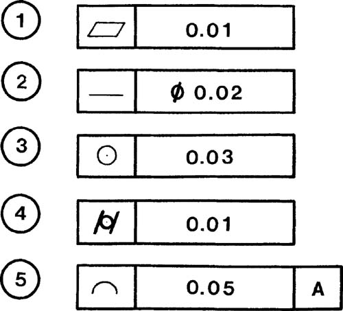
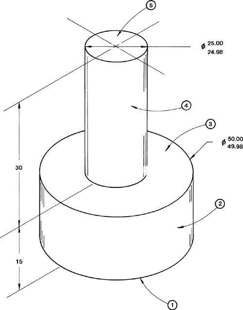
Refer to parts A through G for this exercise problem. Use the format shown and redraw the given geometric tolerance symbols and frame as shown in the sample. Express in words (use Mtext) the meaning of each tolerance callout.


EX10-11 Millimeters
Draw front, top, and right-side views of the object shown, including dimensions. Add the following tolerances and specifications to the drawing:
Surface 1 is datum A.
Surface 2 is datum B and is perpendicular to datum A within 0.1 millimeter.
Surface 3 is datum C and is parallel to datum A within 0.3 millimeter.
Locate a 16-millimeter-diameter hole in the center of the front surface that goes completely through the object. Use positional tolerances to locate the hole. Assign a positional tolerance of 0.02 at MMC perpendicular to datum A.

EX10-12 Inches
Draw front, top, and right-side views of the object shown, including dimensions. Add the following tolerances and specifications to the drawing:
Surface 1 is datum A.
Surface 2 is datum B and is perpendicular to datum A within .003 inch.
Surface 3 is parallel to datum A within .005 inch.
The cylinder’s longitudinal centerline is to be straight within .001 inch at MMC.
Surface 2 is to have circular accuracy within .002 inch.

EX10-13 Millimeters
Draw front, top, and right-side views of the object shown, including dimensions. Add the following tolerances and specifications to the drawing:
Surface 1 is datum A.
Surface 4 is datum B and is perpendicular to datum A within .08 millimeter.
Surface 3 is flat within .03 millimeter.
Surface 5 is parallel to datum A within .01 millimeter.
Surface 2 has a runout tolerance of .2 millimeter relative to surface 4.
Surface 1 is flat within .02 millimeter.
The longitudinal centerline is to be straight within .02 millimeter at MMC and perpendicular to datum A.
EX10-14 Inches
Draw front, top, and right-side views of the object shown, including dimensions. Add the following tolerances and specifications to the drawing:
Surface 2 is datum A.
Surface 6 is perpendicular to datum A with .000 allowable variance at MMC but with a .002-inch MAX variance limit beyond MMC.
Surface 1 is parallel to datum A within .005 inch.
Surface 4 is perpendicular to datum A within .004 inch.

EX10-15 Millimeters
Draw front, top, and right-side views of the object shown, including dimensions. Add the following tolerances and specifications to the drawing:
Surface 1 is datum A.
Surface 2 is datum B.
The hole is located using a true position tolerance value of 0.13 millimeter at MMC. The true position tolerance is referenced to datums A and B.
Surface 1 is to be straight within 0.02 millimeter.
The bottom surface is to be parallel to datum A within 0.03 millimeter.
EX10-16 Millimeters
Draw front, top, and right-side views of the object shown, including dimensions. Add the following tolerances and specifications to the drawing:
Surface 1 is datum A.
Surface 2 is datum B.
Surface 3 is perpendicular to surface 2 within 0.02 millimeter.
The four holes are to be located by using a positional tolerance of 0.07 millimeter at MMC referenced to datums A and B.
The centerlines of the holes are to be straight within 0.01 millimeter at MMC.

EX10-17 Inches
Draw front, top, and right-side views of the object shown, including dimensions. Add the following tolerances and specifications to the drawing:
Surface 1 has a dimension of .378 – .375 inch and is datum A. The surface has a dual primary runout with datum B to within .005 inch. The runout is total.
Surface 2 has a dimension of 1.505 – 1.495 inch. Its runout relative to the dual primary datums A and B is .008 inch. The runout is total.
Surface 3 has a dimension of 1.000 ± .005 and has no geometric tolerance.
Surface 4 has no circular dimension but has a total runout tolerance of .006 inch relative to the dual datums A and B.
Surface 5 has a dimension of .500 – .495 inch and is datum B. It has a dual primary runout with datum A within .005 inch. The runout is total.

EX10-18 Millimeters
Draw front, top, and right-side views of the object shown, including dimensions. Add the following tolerances and specifications to the drawing:
Hole 1 is datum A.
Hole 2 is to have its circular centerline parallel to datum A within 0.2 millimeter at MMC when datum A is at MMC.
Assign a positional tolerance of 0.01 to each hole’s centerline at MMC.

EX10-19 Inches
Draw front, top, and right-side views of the object shown, including dimensions. Add the following tolerances and specifications to the drawing:
Surface 1 is datum A.
Surface 2 is datum B.
The six holes have a diameter range of .500 – .499 inch and are to be located by using positional tolerances so that their centerlines are within .005 inch at MMC relative to datums A and B.
The back surface is to be parallel to datum A within .002 inch.

EX10-20 Millimeters
Draw front, top, and right-side views of the object shown, including dimensions. Add the following tolerances and specifications to the drawing:
Surface 1 is datum A.
Hole 2 is datum B.
The eight holes labeled 3 have diameters of 8.4 – 8.3 millimeters, with a positional tolerance of 0.15 millimeter at MMC relative to datums A and B. Also, the eight holes are to be counterbored to a diameter of 14.6 – 14.4 millimeters and to a depth of 5.0 millimeters.
The large center hole is to have a straightness tolerance of 0.2 at MMC about its centerline.

EX10-21 Millimeters
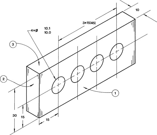
Draw front, top, and right-side views of the object shown, including dimensions. Add the following tolerances and specifications to the drawing:
Surface 1 is datum A.
Surface 2 is datum B.
Surface 3 is datum C.
The four holes labeled 4 have a dimension and tolerance of 8 + 0.3, –0 millimeters. The holes are to be located by using a positional tolerance of 0.05 millimeter at MMC relative to datums A, B, and C.
The six holes labeled 5 have a dimension and tolerance of 6 + 0.2, –0 millimeters. The holes are to be located by using a positional tolerance of 0.01 millimeter at MMC relative to datums A, B, and C.

EX10-22
The objects on the next page labeled A and B are to be toleranced by four different tolerances, as shown. Redraw the charts shown and list the appropriate allowable tolerance for “as measured” increments of 0.1 millimeter or .001 inch. Also include the appropriate geometric tolerance drawing called out above each chart.


EX10-23
Dimension and tolerance parts 1 and 2 so that part 1 always fits into part 2 with a minimum clearance of .005 inch. The tolerance for part 1’s outer matching surface is .006 inch.

EX10-24
Dimension and tolerance parts 1 and 2 so that part 1 always fits into part 2 with a minimum clearance of 0.03 millimeter. The tolerance for part 1’s diameter is 0.05 millimeter. Take into account the fact that the interface is long relative to the diameters.

EX10-25
Prepare front and top views of parts 4A and 4B according to the given dimensions. Add geometric tolerances to produce the stated maximum clearance and mismatch.

EX10-26 Inches–Clearance Fit
The distance between the holes is 2.00 nominal.
The diameter of the fasteners is Ø.375 nominal.
The fasteners have a total tolerance of .001.
The holes have a tolerance of .002.
The minimum allowable clearance between the fastener and the holes is .003.
The material is .375 inch thick.

EX10-27 Millimeters–Clearance Fit
The distance between the holes is 80 nominal.
The nominal diameter of the fasteners is Ø12.
The fasteners have a total tolerance of 0.05.
The holes have a tolerance of 0.03.
The minimum allowable clearance between the fastener and the holes is 0.02.
The material is 12 millimeters thick.
EX10-28 Inches–Clearance Fit
The distance between the holes is 3.50 nominal.
The diameter of the fasteners is Ø.625.
The fasteners have a total tolerance of 0.005.
The holes have a tolerance of 0.003.
The minimum allowable clearance between the fastener and the holes is 0.002.
The material is 0.500 inch thick.
EX10-29 Millimeters–Clearance Fit
The distance between the holes is 120 nominal.
The diameter of the fasteners is Ø24 nominal.
The fasteners have a total tolerance of 0.01.
The holes have a tolerance of 0.02.
The minimum allowable clearance between the fastener and the holes is 0.04.
The material is 20 millimeters thick.
EX10-30 Inches–Interference Fit
The distance between the holes is 2.00 nominal.
The diameter of the fasteners is Ø.250 nominal.
The fasteners have a total tolerance of .001.
The holes have a tolerance of .002.
The maximum allowable interference between the fastener and the holes is .0065.
The material is .438 inch thick.
EX10-31 Millimeters–Interference Fit
The distance between the holes is 80 nominal.
The diameter of the fasteners is Ø10 nominal.
The fasteners have a total tolerance of 0.01.
The holes have a tolerance of 0.02.
The maximum allowable interference between the fastener and the holes is 0.032.
The material is 14 millimeters thick.
EX10-32 Inches–Locational Fit
The distance between the holes is 2.25 nominal.
The diameter of the fasteners is Ø.50 nominal.
The fasteners have a total tolerance of .001.
The holes have a tolerance of .002.
The minimum allowable clearance between the fastener and the holes is .0010.
The material is .370 inch thick.
EX10-33 Millimeters–Transitional Fit
The distance between the holes is 100 nominal.
The diameter of the fasteners is Ø16 nominal.
The fasteners have a total tolerance of 0.01.
The holes are to have a tolerance of 0.02.
The minimum allowable clearance between the fastener and the holes is 0.01.
The material is 20 millimeters thick.
Given a top part and a bottom part in the fixed condition, as shown, add dimensions and tolerances to satisfy the given conditions in Practice Exercises EX10-34 through EX10-41. Size the top and bottom parts and fastener length as needed. Use geometric and positional tolerances.
EX10-34 Inches–Clearance Fit
The distance between the holes is 2.00 nominal.
The diameter of the fasteners is Ø.375 nominal.
The fasteners have a total tolerance of .001.
The holes have a tolerance of .002.
The minimum allowable clearance between the fastener and the holes is .003.
The material is .375 inch thick.

EX10-35 Millimeters–Clearance Fit
The distance between the holes is 80 nominal.
The nominal diameter of the fasteners is Ø12.
The fasteners have a total tolerance of 0.05.
The holes have a tolerance of 0.03.
The minimum allowable clearance between the fastener and the holes is 0.02.
The material is 12 millimeters thick.
EX10-36 Inches–Clearance Fit
The distance between the holes is 3.50 nominal.
The diameter of the fasteners is Ø.625.
The fasteners have a total tolerance of .005.
The holes have a tolerance of .003.
The minimum allowable clearance between the fastener and the holes is .002.
The material is .500 inch thick.
EX10-37 Millimeters–Clearance Fit
The distance between the holes is 120 nominal.
The diameter of the fasteners is Ø24 nominal.
The fasteners have a total tolerance of 0.01.
The holes have a tolerance of 0.02.
The minimum allowable clearance between the fastener and the holes is 0.04.
The material is 20 millimeters thick.
EX10-38 Inches–Interference Fit
The distance between the holes is 2.00 nominal.
The diameter of the fasteners is Ø.250 nominal.
The fasteners have a total tolerance of .001.
The holes have a tolerance of .002.
The maximum allowable interference between the fastener and the holes is .0065.
The material is .438 inch thick.
EX10-39 Millimeters–Interference Fit
The distance between the holes is 80 nominal.
The diameter of the fasteners is Ø10 nominal.
The fasteners have a total tolerance of 0.01.
The holes have a tolerance of 0.02.
The maximum allowable interference between the fastener and the holes is 0.032.
The material is 14 millimeters thick.
EX10-40 Inches–Locational Fit
The distance between the holes is 2.25 nominal.
The diameter of the fasteners is Ø.50 nominal.
The fasteners have a total tolerance of .001.
The holes have a tolerance of .002.
The minimum allowable clearance between the fastener and the holes is .0010.
The material is .370 inch thick.
EX10-41 Millimeters–Transitional Fit
The distance between the holes is 100 nominal.
The diameter of the fasteners is Ø16 nominal.
The fasteners have a total tolerance of 0.01.
The holes are to have a tolerance of 0.02.
The minimum allowable clearance between the fastener and the holes is 0.001.
The material is 20 millimeters thick.
EX10-42
Given the two assemblies that follow, size the parts so that they always fit together. Create individual drawings of each part, including dimensions and tolerances. Use geometric and positional tolerances.

EX10-43
Assume that there are two copies of the part shown and that these parts are to be joined together by four fasteners in the floating condition. Draw front and top views of the object, including dimensions and tolerances. Add the given tolerances and specifications to the drawing and then draw front and top views of a shaft that can be used to join the two objects. The shaft should be able to fit into any of the four holes.
Surface 1 is datum A.
Surface 2 is datum B.
Surface 3 is perpendicular to surface 2 within 0.02 millimeter.
Specify the positional tolerance for the four holes applied at MMC.
The centerlines of the holes are to be straight within 0.01 millimeter at MMC.
The clearance between the shafts and the holes is to be 0.05 minimum and 0.10 maximum.
EX10-44
Assume that there are two copies of the part shown and that these parts are to be joined together by six fasteners in the floating condition. Draw front and top views of the object, including dimensions and tolerances. Add the given tolerances and specifications to the drawing and then draw front and top views of a shaft that can be used to join the two objects. The shaft should be able to fit into any of the six holes.
Surface 1 is datum A.
Surface 2 is round within .003.
Specify the positional tolerance for the six holes applied at MMC.
The clearance between the shafts and the holes is to be .001 minimum and .003 maximum.
