
Chapter 9
Tolerancing
9-1 Introduction
Tolerances define the manufacturing limits for dimensions. All dimensions have tolerances either written directly on a drawing as part of the dimension or implied by a predefined set of standard tolerances that apply to any dimension that does not have a stated tolerance.
This chapter explains general tolerance conventions and how they are applied using AutoCAD. It includes a sample tolerance study and an explanation of standard fits and surface finishes.
Chapter 10 explains geometric tolerances.
9-2 Direct Tolerance Methods
Two methods can be used to include tolerances as part of a dimension: plus and minus, and limits. Plus and minus tolerances can be expressed in either bilateral form or unilateral form.
A bilateral tolerance has both a plus value and a minus value. A unilateral tolerance has either the plus or minus value equal to 0. Figure 9-1 shows a horizontal dimension of 60 millimeters that includes a bilateral tolerance of plus or minus 1 and another dimension of 60 millimeters that includes a bilateral tolerance of plus .20 or minus .10. Figure 9-1 also shows a dimension of 65 millimeters that includes a unilateral tolerance of plus 1 or 0 in the minus position.
Plus or minus tolerances define a range for manufacturing. If inspection shows that all dimensioned distances on an object fall within their specified tolerance range, the object is considered acceptable; that is, it has been manufactured correctly.
The dimension and tolerance 60 ± 1 means that the distance must be manufactured within a range no greater than 61 nor less than 59. The dimension and tolerance 60.00 + 0.20/−0.10 defines the tolerance range as 60.20 to 59.90. The dimension and tolerance 60 + 2/0 defines the tolerance range as 62 to 60.

Figure 9-1
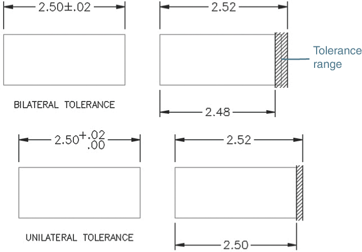
Figure 9-2
Figure 9-2 shows some bilateral and unilateral tolerances applied using decimal inch values. Inch dimensions and tolerances are written in a slightly different format from that used for millimeter dimensions and tolerances, but they also define manufacturing ranges for dimension values. The horizontal bilateral dimension and tolerance 2.50 ± .02 defines the longest acceptable distance as 2.52 inches and the shortest as 2.48. The unilateral dimension 2.50 + .02/−.00 defines the longest acceptable distance as 2.52 and the shortest as 2.50.
9-3 Tolerance Expressions
Dimension and tolerance values are written differently for inch and milli-meter values (Figure 9-3). Unilateral dimensions for millimeter values specify a zero limit with a single 0. A zero limit for inch values must include the same number of decimal places given for the dimension value. In the example shown in Figure 9-3, the dimension value .500 has a unilateral tolerance with minus zero tolerance. The zero limit is written as .000, with three decimal places for both the dimension and the tolerance.

Figure 9-3
Both values in a bilateral tolerance must contain the same number of decimal places, although for millimeter values the tolerance values need not include the same number of decimal places as the dimension value. In Figure 9-3, the dimension value 32 is accompanied by tolerances of +0.25 and −0.10. This form is not acceptable for inch dimensions and tolerances. An equivalent inch dimension and tolerance would be written as 32.00 + 0.25/−0.10.
Degree values must include the same number of decimal places in both the dimension value and the tolerance values for bilateral tolerances. A single 0 may be used for a unilateral tolerance.
9-4 Understanding Plus and Minus Tolerances
A millimeter dimension and tolerance of 12.0 + 0.2/−0.1 means that the longest acceptable distance is 12.2000…0 and the shortest is 11.9000…0. The total range is 0.3000…0.
After an object is manufactured, it is inspected to ensure that the object has been manufactured correctly. Each dimensioned distance is measured and, if it is within the specified tolerance, is accepted. If the measured distance is not within the specified tolerance, the part is rejected. Some rejected objects may be reworked to bring them into the specified tolerance range, whereas others are simply scrapped.
Figure 9-4 shows a dimension with a tolerance. Assume that five objects were manufactured by using the same 12 + 0.2/−0.1 dimension and tolerance. The objects were then inspected, and the results were as listed in the figure. Inspected measurements usually have at least one more decimal place than specified in the tolerance. Which objects are acceptable, and which are not? In this case, object 3 is too long, and object 5 is too short because their measured distances are not within the specified tolerances.
Figure 9-5 shows a dimension and tolerance of 3.50 ± 0.02 inches. Object 3 is not acceptable because it is too short, and object 4 is not acceptable because it is too long.

Figure 9-4

Figure 9-5
9-5 Creating Plus and Minus Tolerances with AutoCAD
You can create plus and minus tolerances using AutoCAD in one of four ways: using the Text option or the Mtext option, using the Text Override tool, typing the tolerances directly using Dtext, or setting the plus and minus values by using the Dimension Style tool.
Creating Plus and Minus Tolerances Using the Text Option
The example given is for a horizontal dimension, but the procedure is the same for any linear or radial dimension.
Select the Linear tool from the Dimensions panel.
Select the extension line origins, as explained in Section 8-3. Drag the dimension line to its location but don’t click to place it.
Specify dimension line location or
[Mtext Text Angle Horizontal Vertical Rotated]:
Type t and press Enter.
Dimension text <x.xxxx>:
Type the appropriate text value and press Enter.
Type <> (open and closed angle bracket to retain the measured value), then %%p, then the tolerance value.
Dimension text <x.xxxx><>%%p.02.
In this example, the resulting dimension shows the real dimension value followed by ± 0.02 (Figure 9-6, top dimension).

Figure 9-6
Creating Plus and Minus Tolerances with the Text Override Tool
Any existing text can be changed by using the Text Override tool. Figure 9-6 shows a 3.00 ± .02 dimension. Say that you want to change that tolerance to ±.03.
Double-click the dimension value.
A box with a shaded background appears around the dimension value.
Delete the existing text by pressing the Delete key.
The value disappears.
Type in the new value and press Enter.
Note
The symbol ± can also be created with the Windows character map: Hold down the Alt key and type 0177.
Using Dtext to Create a Plus and Minus Tolerance
Type Dtext in response to a command prompt.
Place the starting point for the text and then define the appropriate height and angle.
Type 5.00%%p.02 and press Enter.
In the example shown, the resulting dimension is 5.00 ± .02. The symbol initially appears on the screen as %%p but changes to ± when the last text line is entered.
Using the Dimension Style Manager
Access the Dimension Style Manager from the Dimensions panel.
Select the Modify option and then select the Tolerances tab.
Click the arrow to the right of the Method box.
A list of available tolerancing methods appears (Figure 9-7). AutoCAD offers two options for plus and minus tolerancing: Symmetrical and Deviation.

Figure 9-7
Note that the steps below are not all to be taken together. If you are creating symmetrical tolerances, follow steps 4a through 6a. If you are creating deviation tolerances, follow steps 4b through 6b.
Symmetrical Tolerances
4a Select Symmetrical from the Method drop-down (Figure 9-8).

Figure 9-8
5a In the Upper value box, type the value 0.0300.
Only an upper value needs to be entered here because the tolerance value is symmetrical.
6a Return to the drawing screen.
Dimensions created by using the Dimensions panel now automatically include a ±0.0300 tolerance.
Deviation Tolerances
4b Select Deviation from the Method drop-down (Figure 9-9).

Figure 9-9
5b In the Upper value and Lower value boxes, enter the values 0.0100 and 0.0200, respectively.
6b Return to the drawing screen.
Dimensions created by using the Dimensions panel now automatically include a −0.0100, −0.0300 tolerance.
You can also use the Dimension Style Manager to change the precision of the initial AutoCAD-selected dimension values. (The default value is four places: 1.0000.) If, for example, two decimal places are desired, use the Precision box on the Primary Units tab on the Dimension Style Manager dialog box to reset the system for two decimal places (see Section 8-5).
9-6 Limit Tolerances
Figure 9-10 shows examples of limit tolerances. Limit tolerances replace dimension values. Two values are given: the upper and lower limits for the dimension value. The limit tolerance 62.1 and 59.9 is mathematically equal to 62 ± 0.1, but the stated limit tolerance is considered easier to read and understand.
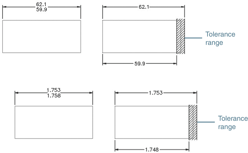
Figure 9-10
Limit tolerances define a range for manufacture. Final distances on an object must fall within the specified range in order to be acceptable.
9-7 Creating Limit Tolerances in AutoCAD
Limit tolerances are created by using AutoCAD in one of two ways: by using the Dimension Style Manager or by modifying a given dimension using the Dimension Edit tool.
Creating a Limit Tolerance Using the Dimension Style Manager
Access the Dimension Style Manager from the Dimensions panel.
Select Modify and then select the Tolerances tab. The Modify Dimension Style: Standard dialog box appears.
Click the arrow to the right of the Method drop-down.
A list of available tolerance methods appears (Figure 9-7).
Select Limits.
The Tolerance format area reappears with the headings Upper value and Lower value now in black letters, meaning that they can be accessed.
Type in the upper and lower values—in this case, 0.0100 and 0.0300 (Figure 9-11).
Return to the drawing screen.

Figure 9-11
Every dimension created with the Linear dimension tool now automatically creates a limit tolerance on the basis of the selected distance and the selected upper and lower values. Figure 9-11 shows the results of the Linear dimension tool applied to the distance 3.2500. The upper limit is 3.2500+0.0100, and the lower limit is 3.2500−0.0300.
Note
If only a few limit-type tolerances are to be used on a drawing, it is sometimes easier simply to modify an existing dimension than to change the Tolerance settings.
Using the Properties Palette to Change an Existing Dimension to a Limit Tolerance Dimension
Open the Properties palette by pressing Ctrl+1. Select the dimension (Figure 9-12).

Figure 9-12
In the Properties palette, scroll to the Tolerances section at the bottom of the list of properties.
On the Tolerance display row, click None. From the drop-down, select Limits.
The Tolerance limit lower and Tolerance limit upper boxes become active.
Highlight the text in the box and type in the new text.
Click the drawing screen.
Figure 9-12 shows the resulting changed dimension.
9-8 Angular Tolerances
Figure 9-13 shows an example of an angular dimension with a tolerance. The procedure explained for plus and minus tolerances applies to angular, as well as to linear, dimensions and tolerances.

Figure 9-13
The precision of angular dimensions is set using the Primary Units dialog box. In the example that follows, a deviation tolerance of +0.10, −0.30 was also specified.
Setting the Precision for Angular Dimensions and Tolerances
Access the Dimension Style Manager, select Modify, and then select the Primary Units tab.
Click the arrow to the right of Precision.
A list of available precision factors appears.
Select two significant figures for both Dimension and Tolerance and then return to the drawing screen.
The precision for the angular value can be changed by using the Precision option under Angular Dimensions.
Creating an Angular Dimension and Tolerance
Select Angular from the Dimension tool on the Dimensions panel.
Select arc, circle, line, or <specify vertex>:
Select one of the lines that define the angle.
Select second line:
Select the second line.
Specify dimension arc line location or [Mtext Text Angle]:
Select a location for the dimension and press Enter.
The Mtext and Text options are used as explained for linear dimensions and tolerance in Section 9-5. Symmetrical, deviation, and limit tolerances can be applied to angular tolerances in the same way that they are applied to linear tolerances.
9-9 Standard Tolerances
A manufacturer is likely to establish a set of standard tolerances that are applied to any dimension that does not include a specific tolerance. Figure 9-14 shows some possible standard tolerances. Standard tolerances vary from company to company. Standard tolerances are usually listed on the first page of a drawing to the left of the title block, but this location may vary.
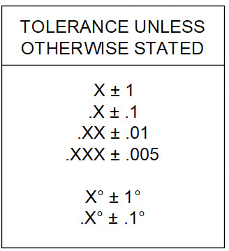
Figure 9-14
The X value used when specifying standard tolerances means any X stated in that format. The dimension value 52.00 has an implied tolerance of ± .01. This is because the stated standard tolerance is .XX ± .01, so any dimension value with two decimal places has a standard implied tolerance of ± .01. The dimension value 52.000 has an implied tolerance of ± .005.
9-10 Double Dimensioning
It is an error, called double dimensioning, to dimension the same distance twice. Double dimensioning is an error because it does not allow for tolerance buildup across a distance.
Figure 9-15 shows an object that has been dimensioned twice across its horizontal length: once by using three 30-millimeter dimensions and a second time by using the 90-millimeter overall dimension. The two dimensions are mathematically equal, but they are not equal when tolerances are considered. Assume that each dimension has a standard tolerance of ±1 millimeter. The three 30-millimeter dimensions could create an acceptable distance of 90 ± 3 millimeters, or a maximum distance of 93 and a minimum distance of 87. The overall dimension of 90 millimeters allows a maximum distance of 91 and a minimum distance of 89. The two dimensions yield different results when tolerances are considered.

Figure 9-15
The size and location of a tolerance depends on the design objectives for the object, how the object will be manufactured, and how it will be inspected. Even objects that have similar shapes may be dimensioned and toleranced very differently.
One possible solution to the double dimensioning shown in Figure 9-15 is to remove one of the 30-millimeter dimensions and to allow that distance to “float”—that is, absorb the cumulated tolerances. The choice of which 30-millimeter dimension to eliminate depends on the design objectives for the part. For this example, the far-right dimension was eliminated to remove the double dimensioning error.
Another possible solution to the double dimensioning error is to retain the three 30-millimeter dimensions and to change the 90-millimeter overall dimension to a reference dimension. A reference dimension is used only for mathematical convenience. It is not used during the manufacturing or inspection process. A reference dimension is designated on a drawing with parentheses: (90).
If the 90-millimeter dimension were referenced, then only the three 30-millimeter dimensions would be used to manufacture and inspect the object. This would eliminate the double dimensioning error.
9-11 Chain Dimensions and Baseline Dimensions
Two systems are used to apply dimensions and tolerances to a drawing: chain and baseline. Figure 9-16 shows examples of both systems. Chain dimensions relate each feature to the feature next to it; baseline dimensions relate all features to a single baseline or datum.

Figure 9-16
Chain and baseline dimensions may be used together. Figure 9-16 also shows two objects with repetitive features: one object includes two slots, and the other object includes three sets of three holes. In each example, the center of the repetitive feature is dimensioned to the left side of the object, which serves as a baseline. The sizes of the individual features are dimensioned by using chain dimensions referenced to centerlines.
Baseline dimensions eliminate tolerance buildup and can be related directly to the reference axis of many machines. They tend to take up much more area on a drawing than do chain dimensions.
Chain dimensions are useful in relating one feature to another, such as the repetitive hole pattern shown in Figure 9-16. In this example, the distance between the holes is more important than the distance of the individual hole from the baseline.
Figure 9-17 shows the same object dimensioned twice, once using chain dimensions and once using baseline dimensions. All distances are assigned a tolerance range of 2 millimeters, stated in terms of limit tolerances. The maximum distance for line A is 28 millimeters by the chain system and 27 millimeters by the baseline system. The 1-millimeter difference comes from the elimination of the first 26 − 24 limit dimension found on the chain example but not on the baseline.

Figure 9-17
The total tolerance difference is 6 millimeters for the chain and 4 millimeters for the baseline. The baseline reduces the tolerance variations for the object simply because it applies the tolerances and dimensions differently. So why not always use baseline dimensions? For most applications, the baseline system is probably better, but if the distance between the individual features is more critical than the distance from the feature to the baseline, it is advisable to use the chain system.
Creating Baseline Dimensions
The Baseline tool can be applied only after a linear dimension has been created. The object shown in Figure 9-18 was dimensioned by first creating the 1.00 dimension by use of the Linear dimension tool and then by using the Baseline tool, as follows:
Create a linear dimension with the Linear tool from the Dimensions panel.

Figure 9-18
The point selected as the origin for the first extension line becomes the origin of the baseline.
Select the Baseline tool from the Dimensions panel.
Specify a second extension line origin or [Undo Select] <Select>:
Select the origin for the second extension line of the baseline dimension.
Specify a second extension line origin or [Undo Select] <Select>:
Repeat the process until the baseline dimensioning is complete.
Right-click and press Enter.
When you create a series of baseline dimensions, the spacing between dimension lines is often too close. You can use the Dimspace command to equally space the dimension lines a more suitable distance apart, as described in the following steps.
Type Dimspace and press Enter or click the Adjust Space button on the Dimensions panel.
Select base dimension:
Select the first dimension you created.
Select dimensions to space:
Select the remaining baseline dimensions and press Enter.
Enter value of [Auto] <Auto>:
Press Enter to automatically space the baseline dimensions or enter a specific value.
9-12 Tolerance Studies
The term tolerance study is used when analyzing the effects of a group of tolerances on each other and on an object. Figure 9-19 shows an object on the left with two horizontal dimensions. The horizontal distance A is not dimensioned. Its length depends on the tolerances of the two horizontal dimensions.
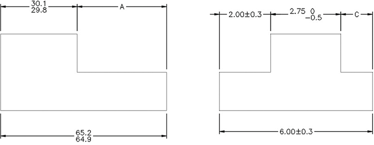
Figure 9-19
Calculating A’s Maximum Length
Distance A is longest when the overall distance is at its longest and the other distance is at its shortest:

Calculating A’s Minimum Length
Distance A is shortest when the overall length is at its shortest and the other length is at its longest:

Figure 9-19 shows a second figure that includes three horizontal dimensions. Distance C is at its maximum length when the overall dimension is at its longest and the other dimensions are at their shortest. Distance C is at its minimum length when the overall length is at its shortest and the other dimensions are at their longest.
9-13 Rectangular Dimensions
Figure 9-20 shows an example of rectangular dimensions referenced to baselines. Figure 9-21 shows a circular object for which dimensions are referenced to a circle’s centerlines. Dimensioning to a circle’s centerline is critical to accurate hole location.

Figure 9-20

Figure 9-21
9-14 Hole Locations
When rectangular dimensions are used, the location of a hole’s center point is defined by two linear dimensions. The result is a rectangular tolerance zone whose size is based on the linear dimension’s tolerances. The shape of the center point’s tolerance zone may be changed to circular by positional tolerancing, as described in Section 10-16.
Figure 9-22 shows the location and size dimensions for a hole. Also shown are the resulting tolerance zone and the overall possible hole shape. The center point’s tolerance is ± 0.2 by ± 0.3, based on the given linear locating tolerances.

Figure 9-22
The hole diameter has a tolerance of ± 0.05. This value must be added to the center point location tolerances to define the maximum possible overall shape of the hole. The maximum possible hole shape is determined by drawing the maximum radius from the four corner points of the tolerance zone. This means that the left edge of the hole could be as close to the vertical baseline as 12.75 or as far as 13.25. The 12.75 value was derived by subtracting the maximum hole diameter value, 12.05, from the minimum linear distance, 24.80 (24.80 − 12.05 = 12.75). The 13.25 value was derived by subtracting the minimum hole diameter, 11.95, from the maximum linear distance, 25.20 (25.20 − 11.95 = 13.25).
Figure 9-23 shows a hole’s tolerance zone based on polar dimensions. The zone has a sector shape, and the possible hole shape is determined by locating the maximum radius at the four corner points of the tolerance zone.

Figure 9-23
9-15 Choosing a Shaft for a Toleranced Hole
Given the hole location and size shown in Figure 9-23, what is the largest-diameter shaft that will always fit into the hole?
Figure 9-24 shows the hole’s center point tolerance zone based on the given linear locating tolerances. Four circles drawn centered at the four corners of the linear tolerance zone represent the smallest possible hole diameter. The circles define an area that represents the maximum shaft size that will always fit into the hole, regardless of how the given dimensions are applied.

Figure 9-24
The diameter of this circular area can be calculated by subtracting the maximum diagonal distance across the linear tolerance zone (corner to corner) from the minimum hole diameter.
The results can be expressed as a formula.
For Linear Dimensions and Tolerances
Smax = Hmin − DTZ
where
Smax = Maximum shaft diameter
Hmin = Minimum hole diameter
DTZ = Diagonal distance across the tolerance zone
In the example shown, the diagonal distance is determined by using the Pythagorean theorem:

This means that the maximum shaft diameter that will always fit into the given hole is 11.23.

This procedure represents a restricted application of the general formula for positional tolerances presented in Chapter 10. For a more complete discussion, see Section 10-16. Once the maximum shaft size has been established, a tolerance can be applied to the shaft. If the shaft had a total tolerance of 0.25, the minimum shaft diameter would be 11.23 − 0.25, or 10.98. Figure 9-24 shows a shaft dimensioned and toleranced according to these values.
The formula presented is based on the assumption that the shaft is perfectly placed on the hole’s center point. This assumption is reasonable if two objects are joined by a fastener and both objects are free to move. When both objects are free to move about a common fastener, they are called floating objects.
9-16 Drawing Problem
Parts A and B in Figure 9-25 are to be joined by a common shaft. The total tolerance for the shaft is to be 0.05. What are the maximum and minimum shaft diameters?

Figure 9-25
Both objects have the same dimensions and tolerances and are floating relative to each other.

The shaft’s minimum diameter is found by subtracting the total tolerance requirement from the calculated maximum diameter.
15.08 − .05 = 15.03
Therefore,
Shaft max = 15.08
Shaft min = 15.03
9-17 Drawing Problem
The procedure presented in the drawing problem in Section 9-16 can be worked in reverse to determine the maximum and minimum hole sizes, according to a given shaft size.
Objects AA and BB in Figure 9-26 are to be joined by a bolt whose maximum diameter is 0.248. What is the minimum hole size for the objects that will always accept the bolt? What is the maximum hole size if the total hole tolerance is 0.007?
Smax = Hmin − DTZ

Figure 9-26
In this example, Hmin is the unknown factor, so the equation is rewritten:

This is the minimum hole diameter, so the total tolerance requirement is added to this value:
.258 + .007 = .265
Therefore,
Hole max = .265
Hole min = .258
9-18 Standard Fits (Metric Values)
Calculating tolerances between holes and shafts that fit together is so common in engineering design that a group of standard values and notations has been established.
There are three possible types of fits between a shaft and a hole: clearance, interference, and transition (Figure 9-27). There are several subclassifications within each of these categories.

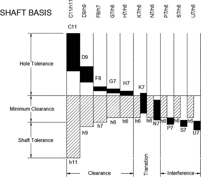
Figure 9-27
A clearance fit always defines the maximum shaft diameter as smaller than the minimum hole diameter. The difference between the two diameters is the amount of clearance. It is possible for a clearance fit to be defined with zero clearance; this means that the maximum shaft diameter is equal to the minimum hole diameter.
An interference fit always defines the minimum shaft diameter as larger than the maximum hole diameter; that is, the shaft is always bigger than the hole. An interference fit is the converse of a clearance fit. The difference between the diameter of the shaft and the hole is the amount of interference.
An interference fit is primarily used to assemble objects together. Interference fits eliminate the need for threads, welds, or other joining methods. Using an interference fit for joining two objects is generally limited to light-load applications.
It is sometimes difficult to visualize how a shaft can be assembled into a hole with a diameter smaller than that of the shaft. It is sometimes done by a hydraulic press that slowly forces the two parts together. The joining process can be augmented by the use of lubricants or heat. The hole is heated, causing it to expand, the shaft is inserted, and the hole is allowed to cool and shrink around the shaft.
A transition fit may be either a clearance fit or an interference fit. There may be a clearance between the shaft and the hole, or there may be an interference.
Figure 9-27 shows two graphic representations of 20 different standard hole/shaft tolerance ranges. The figure shows ranges for hole tolerances, shaft tolerances, and the amount of clearance or interference for each classification. The notations are based on Standard International Tolerance values. A specific description for each category of fit follows.
Clearance Fits
H11/c11 or C11/h11 = Loose running fit
H9/d9 or D9/h9 = Free running fit
H8/f7 or F8/h7 = Close running fit
H7/g6 or G7/h6 = Sliding fit
H7/h6 = Locational clearance fit
Transition Fits
H7/k6 or K7/h6 = Locational transition fit
H7/n6 or N7/h6 = Locational transition fit
Interference Fits
H7/p6 or P7/h6 = Locational transition fit
H7/s6 or S7/h6 = Medium drive fit
H7/u6 or U7/h6 = Force fit
Not all possible sizes can be listed in this book. See the online Appendix, which lists preferred sizes. Tolerances for sizes between the stated sizes are derived by going to the next nearest given size. The values are not interpolated. A basic size of 27 would use the tolerance values listed for 25. Sizes that are exactly halfway between two stated sizes may use either set of values, depending on the design requirements.
9-19 Nominal Sizes
The term nominal refers to the approximate size of an object that matches a common fraction or whole number. A shaft with dimension 1.500 ± 0.003 is said to have a nominal size of “one and a half inches.” The dimension 1.500 + 0.000/−0.005 is also said to have a nominal size of “one and a half inches.” In both examples, 1.5 is the closest common fraction.
9-20 Hole and Shaft Basis
One of the charts shown in Figure 9-27 applies tolerances starting with the nominal hole sizes, called hole basis tolerances; the other applies tolerances starting with the shaft nominal sizes, called shaft basis tolerances. The choice of which set of values to use depends on the design application. In general, hole basis numbers are used more often because it is more difficult to vary hole diameters manufactured by the use of specific drill sizes than shaft sizes manufactured by the use of a lathe. Shaft sizes may be used when a specific fastener diameter is used to assemble several objects.
Figure 9-28 shows a hole, a shaft, and a set of values taken from tables in the online Appendix. One set of values is for hole basis tolerance, and the other set is for shaft basis tolerance. The fit values are the same for both sets of values. The hole basis values were derived starting with a nominal hole size of 20.000, whereas the shaft basis values were derived starting with a shaft nominal size of 20.000. The letters used to identify holes are always written in capital letters, and the letters for shaft values are lowercase.
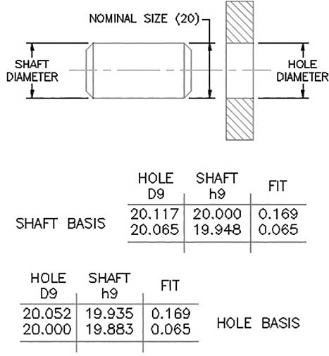
Figure 9-28
Additional fit tolerances can be found on the Web. Search for fits and tolerances.
9-21 Drawing Problem
Dimension a hole and a shaft that are to fit together, using a preferred clearance fit. Use hole basis values based on a nominal size of 12 mm.
Figure 9-29 shows values taken from the appropriate table in the online Appendix. The values may be applied directly to the shaft and hole as shown.

Figure 9-29
9-22 Standard Fits (Inch Values)
The online Appendix includes tables of standard fit tolerances for inch values. The tables for inches are presented for a range of nominal values and are not for specific values, as are the metric value tables. The values may be on a hole or shaft basis.
Fits Defined by Inch Values
Fits defined by inch values are classified as follows:
RC = Running and sliding fits
LC = Clearance locational fits
LT = Transitional locational fits
LN = Interference fits
FN = Force fits
Each of these general categories has several subclassifications within it, defined by a number—for example, Class RC1, Class RC2, and so on through Class RC9. The letter designations are based on International Tolerance Standards, as are metric designations.
The values are listed in thousandths of an inch. A table value of 1.1 means 0.0011 inch. A table value of 0.5 means 0.0005 inch.
Figure 9-30 shows a set of values for a Class RC3 clearance fit hole basis taken from the online Appendix. If the values are applied to a nominal size of 0.5 inch, the resulting hole and shaft sizes are as shown. Plus table values are added to the nominal value; minus values are subtracted from the nominal value.

Figure 9-30
Nominal values that are common to two nominal ranges (such as 0.71) may use values from either range.
9-23 Drawing Problem
Dimension a hole and shaft for a Class LN1 interference fit based on a nominal diameter of 0.25 inches. Use hole basis values.
Figure 9-31 shows the values for the 0.24 − 0.40 nominal range as listed in the online Appendix. The values are in thousandths of an inch. Plus values are added to the nominal size. The resulting shaft and hole dimensions are as shown. The diameter of the shaft is larger than that of the hole because this example calls for an interference fit.

Figure 9-31
9-24 Preferred and Standard Sizes
It is important that designers always consider preferred and standard sizes when selecting sizes for designs. Most tooling is set up to match these sizes, so manufacturing is greatly simplified when preferred and standard sizes are specified. Figure 9-32 shows a list of preferred sizes for metric values.

Figure 9-32
Consider the case of design calculations that call for a 42-mm-diameter hole. A 42-mm-diameter hole is not a preferred size. A diameter of 40 mm is the closest preferred size, and a 45-mm diameter is a second choice. A 42-mm hole could be manufactured but would require an unusual drill size that may not be available. It would be wise to reconsider the design to see whether a 40-mm-diameter hole could be used, and if not, then a 45-mm-diameter hole possibly could be used.
A very large-quantity production run could possibly justify the cost of special tooling, but for smaller runs, it is probably better to use preferred sizes. Machinists have the required drills, and maintenance people have the appropriate tools for these sizes.
Figure 9-33 lists standard fractional drill sizes. Most companies now specify metric units or decimal inches; however, many standard items are still available in fractional sizes, and many older objects may still require fractional-sized tools and replacement parts. A more complete list is available in the online Appendix.

Figure 9-33
9-25 Surface Finishes
The term surface finish refers to the accuracy (flatness) of a surface. Metric values are measured in micrometers (μm), and inch values are measured in microinches (μin).
The accuracy of a surface depends on the manufacturing process used to produce the surface. Figure 9-34 lists several manufacturing processes and the quality of the surface finish each can be expected to produce.


Figure 9-34
Surface finishes have several design applications. Datum surfaces, or surfaces used for baseline dimensioning, should have fairly accurate surface finishes to help ensure accurate measurements; bearing surfaces should have good-quality surface finishes for better load distribution; and parts that operate at high speeds should have smooth finishes to help reduce friction.
Figure 9-35 shows a screw head sitting on a very wavy surface. Note that the head of the screw is in contact with only two wave peaks, meaning that the entire bearing load is concentrated on the two peaks. This situation could cause stress cracks, which could greatly weaken the surface. A better-quality surface finish would increase the bearing contact area.
Figure 9-35 also shows two very rough surfaces moving in contact with each other. The result will be excess wear to both surfaces because the surfaces touch only on the peaks, and these peaks will tend to wear faster than flatter areas. Excess vibration can also result when interfacing surfaces are too rough.
Surface finishes are classified into three categories: surface texture, roughness, and lay. Surface texture is a general term that refers to the overall quality and accuracy of a surface.
Roughness is a measure of the average deviation of a surface’s peaks and valleys (Figure 9-36).
Lay refers to the direction of machine marks on a surface. See Figure 9-37. The lay of a surface is particularly important when two moving objects are in contact with each other, especially at high speeds.

Figure 9-35

Figure 9-36

Figure 9-37
9-26 Surface Control Symbols
Surface finishes are indicated on a drawing with surface control symbols (Figure 9-38). The general surface control symbol looks like a check mark. Roughness values may be included with the symbol to specify the required accuracy. Surface control symbols can also be used to specify the manufacturing process that may or may not be used to produce a surface.
Figure 9-39 shows two applications of surface control symbols. In the first example, a 0.8-μm (32-μin) surface finish is specified on the surface that serves as a datum for several horizontal dimensions. A 0.8-μm surface finish is generally considered the minimum acceptable finish for a datum.
A second finish mark with a value of 0.4 μm is located on an extension line that refers to a surface that will be in contact with a moving object. The extra flatness will help prevent wear between the two surfaces.
It is suggested that a general finish mark be drawn and saved as a drawing file with the Wblock command so that it can be inserted as needed on future drawings.
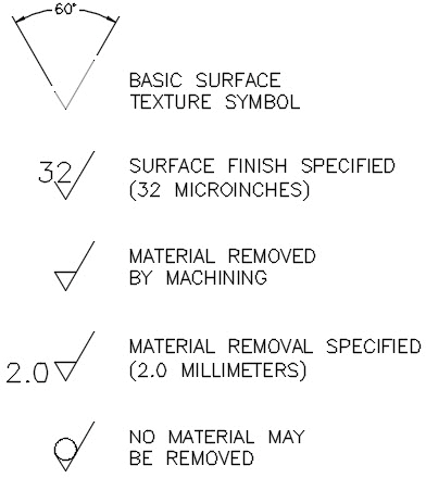
Figure 9-38

Figure 9-39
9-27 Drawing Problem
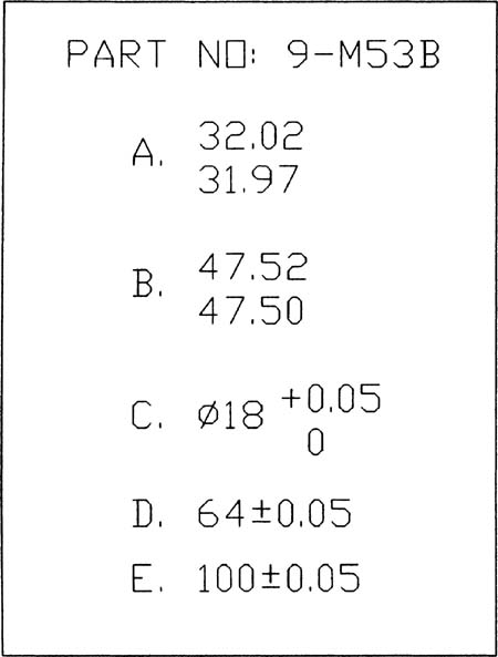
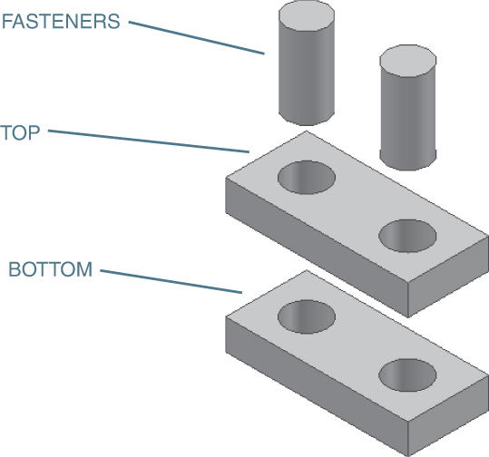
Figure 9-40 shows two objects that are to be fitted together using a fastener such as a screw-and-nut combination. For this example, a cylinder will be used to represent a fastener. Only two nominal dimensions are given. The dimensions and tolerances were derived as follows.
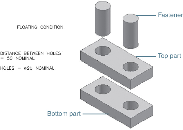
Figure 9-40
The distance between the centers of the holes is given as 50 nominal. The term nominal means that the stated value is only a starting point. The final dimensions will be close to the given value but do not have to equal it.
Assigning tolerances is an iteration process; that is, a tolerance is selected, and other tolerance values are calculated from the selected initial values. If the results are not satisfactory, go back and modify the initial value and calculate the other values again. As your experience grows, you will become better at selecting realistic initial values.
In the example shown in Figure 9-40, start by assigning a tolerance of ± 0.01 to both the top and bottom parts for both the horizontal and vertical dimensions used to locate the holes. This means that there is a possible center point variation of 0.02 for both parts. The parts must always fit together, so tolerances must be assigned on the basis of a worst-case condition, or when the parts are made at the extreme ends of the assigned tolerances.
Figure 9-41 shows a greatly enlarged picture of the worst-case condition created by a tolerance of ± 0.01. The center points of the two holes could be as much as 0.028 apart if they were located at opposite corners of the tolerance zones. This means that the minimum hole diameter must always be at least 0.028 larger than the maximum stud diameter (see Section 9-15). In addition, there should be a clearance tolerance assigned so that the hole and stud are never exactly the same size.
Figure 9-42 shows the resulting tolerances. The 19.96 value includes a 0.1 clearance allowance, and the 19.94 value is the result of an assigned feature tolerance of .02.

Figure 9-41

Figure 9-42
Floating Condition
The top and bottom parts shown in Figure 9-40 are to be joined by two independent fasteners; that is, the location of one fastener does not depend on the location of the other. This is called a floating condition. This means that the tolerance zones for both the top and bottom parts can be assigned the same values and that a fastener diameter selected to fit one part will also fit the other part.
The final tolerances are developed by first defining a minimum hole size of 20.00. An arbitrary tolerance of 0.02 is assigned to the hole and is expressed as 20.00 + 0.02/−0 so that the hole can never be any smaller than 20.00.
The 20.00 minimum hole diameter dictates that the maximum fastener diameter can be no greater than 19.97, or 0.03 (i.e., the rounded-off diagonal distance across the tolerance zone—0.028) less than the minimum hole diameter. A 0.01 clearance is assigned. The clearance ensures that the hole and fastener are never exactly the same diameter. The resulting maximum allowable diameter for the fastener is 19.96. Again, an arbitrary tolerance of 0.02 is assigned to the fastener. The final fastener dimensions are, therefore, 19.96 to 19.94.
The assigned tolerances ensure that there will always be at least 0.01 clearance between the fastener and the hole. The other extreme condition occurs when the hole is at its largest possible size (10.02) and the fastener is at its smallest (19.94). This means that there could be as much as 0.08 clearance between the parts. If this much clearance is not acceptable, then the assigned tolerances will have to be reevaluated.
Figure 9-43 shows the top and bottom parts dimensioned and toleranced. Any dimensions that do not have assigned tolerances are assumed to have standard tolerances (refer to Figure 9-14).

Figure 9-43
Note in Figure 9-43 that the top edge of each part was assigned a surface finish. This was done to help ensure the accuracy of the 20 ± 0.01 dimension. If this edge surface were rough, it could affect the tolerance measurements.
This example will be repeated in Chapter 10 with geometric tolerances. Geometric tolerance zones are circular rather than rectangular.
Fixed Condition
Figure 9-44 shows the same nominal conditions presented in Figure 9-40, but the fasteners are now fixed to the top part. This is called a fixed condition. In analyzing the tolerance zones for the fixed condition, you must consider two positional tolerances: the positional tolerances for the holes in the bottom part and the positional tolerances for the fixed fasteners in the top part. This may be expressed in an equation as follows:
Smax + DTSZ = Hmin − DTZ
where
Smax = Maximum shaft (fastener) diameter
Hmin = Minimum hole diameter
DTSZ = Diagonal distance across the shaft’s center point tolerance zone
DTZ = Diagonal distance across the hole’s center point tolerance zone
If a dimension and tolerance of 50 ± 0.01 and 20 ± 0.01 are assigned to both the center distance between the holes and the center distance between the fixed fasteners, the values for DTSZ and DTZ will be equal. The formula can then be simplified as follows:
Smax = Hmin − 2(DTZ)
Here, DTZ equals the diagonal distance across the tolerance zone. If a hole tolerance of 20.00 + 0.02/−0 is also defined, the resulting maximum shaft size can be determined, assuming that the calculated distance of 0.028 is rounded to 0.03 (Figure 9-45).
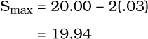

Figure 9-44

Figure 9-45
This means that the largest possible shaft diameter that will just fit equals 19.94. If a clearance tolerance of 0.01 is assumed to ensure that the shaft and hole are never exactly the same size, the maximum shaft diameter becomes 19.93 (Figure 9-46).

Figure 9-46
A feature tolerance of 0.02 on the shaft will result in a minimum shaft diameter of 19.91. Note that the 0.01 clearance tolerance and the 0.02 feature tolerance were arbitrarily chosen. Other possible values could have been used.
Designing a Hole Given a Fastener Size
The previous two examples started by selecting a minimum hole diameter and then calculating the resulting fastener size. Figure 9-47 shows a situation in which the fastener size is defined and the problem is to determine the appropriate hole sizes. Figure 9-48 shows the dimensions and tolerances for both top and bottom parts.

Figure 9-47

Figure 9-48
Requirements:
Clearance, minimum = 0.003
Hole tolerances = 0.005
Positional tolerance = 0.002
9-28 Exercise Problems
Redraw the objects shown in Exercise Problems EX9-1 through EX9-4, using the given dimensions. Include the listed tolerances.
EX9-1 Millimeters


EX9-2 Millimeters

EX9-3 Inches

EX9-4 Inches


EX9-5 Millimeters
Redraw the following object, including the given dimensions and tolerances. Calculate and list the maximum and minimum distances for surface A.

EX9-6 Inches
Redraw the following object, including the dimensions and tolerances. Calculate and list the maximum and minimum distances for surface A.
Redraw the given object and dimension it, using baseline dimensions. Calculate and list the maximum and minimum distances for surface A.

EX9-7 Millimeters
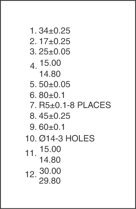
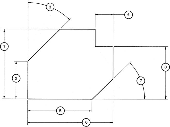
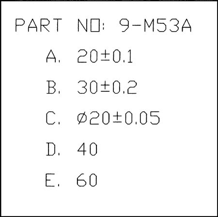
Redraw the following object, including the dimensions and tolerances. Calculate and list the maximum and minimum distances for surfaces D and E.

EX9-8 Millimeters
Dimension the following object twice: once using chain dimensions and once using baseline dimensions. Calculate and list the maximum and minimum distances for surface D for both chain and baseline dimensions. Compare the results.

EX9-9 Inches
Redraw the following shapes, including the dimensions and tolerances. Also list the required minimum and maximum values for the specified distances.

EX9-10
Redraw and complete the inspection report that follows. Under the Results column classify each “AS MEASURED” value as OK if the value is within the stated tolerances, REWORK if the value indicates that the measured value is beyond the stated tolerance but can be reworked to bring it into the acceptable range, or SCRAP if the value is not within the tolerance range and cannot be reworked to make it acceptable.

EX9-11 Millimeters
Redraw the following charts and complete them on the basis of the following information:
Nominal = 16, Fit = H9/d9
Nominal = 30, Fit = H11/c11
Nominal = 22, Fit = H7/g6
Nominal = 10, Fit = C11/h11
Nominal = 25, Fit = F8/h7
Nominal = 12, Fit = H7/k6
Nominal = 3, Fit = H7/p6
Nominal = 19, Fit = H7/s6
Nominal = 27, Fit = H7/u6
Nominal = 30, Fit = N7/h6

EX9-12 Inches
Redraw the following charts and complete them on the basis of the following information:
Nominal = 0.25, Fit = Class LC5
Nominal = 1.00, Fit = Class LC7
Nominal = 1.50, Fit = Class LC10
Nominal = 0.75, Fit = Class RC3
Nominal = 2.50, Fit = Class RC6
Nominal = 0.500, Fit = Class LT2
Nominal = 1.25, Fit = Class LT5
Nominal = 3.00, Fit = Class LN3
Nominal = 1.625, Fit = Class FN1
Nominal = 2.00, Fit = Class FN4

Draw the chart shown in EX9-13 and add the appropriate values according to the dimensions and tolerances given in Exercise Problems EX9-13 through EX9-16.
EX9-13 Millimeters

EX9-14 Millimeters

EX9-15 Millimeters
EX9-16 Millimeters

EX9-17 Millimeters
Prepare front and top views of parts 4A and 4B on the basis of the given dimensions. Add tolerances to produce the stated clearances.

EX9-18 Inches
Redraw parts A and B and add dimensions and tolerances to meet the “UPON ASSEMBLED” requirements.


EX9-19 Millimeters
Draw a front and a top view of each given object. Add dimensions and tolerances to meet the “FINAL CONDITION” requirements.

EX9-20 Inches
Given the nominal sizes that follow, dimension tolerance parts AM311 and AM312 so that they always fit together, regardless of orientation. Further, dimension the overall lengths of each part so that, in the assembled condition, they will always pass through a clearance gauge with an opening of 90.00 ± 0.02.

EX9-21 Millimeters
Design a bracket that supports the three Ø100 wheels shown. The wheels should use three Ø5.00 ± 0.01 shafts attached to the bracket. The bottom of the bracket must have a minimum of 10 millimeters from the ground. The wall thickness of the bracket must always be at least 5 millimeters, and the minimum bracket opening must be at least 15 millimeters.
Prepare front and side views of the bracket.
Draw the wheels in their relative positions, using phantom lines.
Add all appropriate dimensions and tolerances.

Given a top and bottom part in the floating condition, as shown in Figure EX9-22, add dimensions and tolerances to satisfy the given conditions. Size the top and bottom parts and fastener length as needed.
EX9-22 Inches−Clearance Fit
The distance between the holes is 2.00 nominal.
The diameter of the fasteners is Ø.375 nominal.
The fasteners have a total tolerance of 0.001.1.
The holes have a tolerance of 0.002.
The minimum allowable clearance between the fastener and the holes is 0.003.
The material is 0.375 inch thick.
EX9-23 Millimeters−Clearance Fit
The distance between the holes is 80 nominal.
The nominal diameter of the fasteners is Ø12.
The fasteners have a total tolerance of 0.05.
The holes have a tolerance of 0.03.
The minimum allowable clearance between the fastener and the holes is 0.02.
The material is 12 millimeters thick.

EX9-24 Inches−Clearance Fit
The distance between the holes is 3.50 nominal.
The diameter of the fasteners is Ø.625.
The fasteners have a total tolerance of 0.005.
The holes have a tolerance of 0.003.
The minimum allowable clearance between the fastener and the holes is 0.002.
The material is 0.500 inch thick.
EX9-25 Millimeters−Clearance Fit
The distance between the holes is 120 nominal.
The diameter of the fasteners is Ø24 nominal.
The fasteners have a total tolerance of 0.01.
The holes have a tolerance of 0.02.
The minimum allowable clearance between the fastener and the holes is 0.04.
The material is 20 millimeters thick.
EX9-26 Inches−Interference Fit
The distance between the holes is 2.00 nominal.
The diameter of the fasteners is Ø.250 nominal.
The fasteners have a total tolerance of 0.001.
The holes have a tolerance of 0.002.
The maximum allowable interference between the fastener and the holes is 0.0065.
The material is 0.438 inch thick.
EX9-27 Millimeters−Interference Fit
The distance between the holes is 80 nominal.
The diameter of the fasteners is Ø10 nominal.
The fasteners have a total tolerance of 0.01.
The holes have a tolerance of 0.02.
The maximum allowable interference between the fastener and the holes is 0.032.
The material is 14 millimeters thick.
EX9-28 Inches−Locational Fit
The distance between the holes is 2.25 nominal.
The diameter of the fasteners is Ø.50 nominal.
The fasteners have a total tolerance of 0.001.
The holes have a tolerance of 0.002.
The minimum allowable clearance between the fastener and the holes is 0.0010.
The material is 0.370 inch thick.
EX9-29 Millimeters−Transitional Fit
The distance between the holes is 100 nominal.
The diameter of the fasteners is Ø16 nominal.
The fasteners have a total tolerance of 0.01.
The holes have a tolerance of 0.02.
The minimum allowable clearance between the fastener and the holes is 0.01.
The material is 20 millimeters thick.
Given a top part and a bottom part in the fixed condition, as shown in Figure EX9-23, add dimensions and tolerances to satisfy the given conditions. Size the top and bottom parts and fastener length as needed.
EX9-30 Inches−Clearance Fit
The distance between the holes is 2.00 nominal.
The diameter of the fasteners is Ø.375 nominal.
The fasteners have a total tolerance of 0.001.
The holes have a tolerance of 0.002.
The minimum allowable clearance between the fastener and the holes is 0.003.
The material is 0.375 inch thick.
EX9-31 Millimeters−Clearance Fit
The distance between the holes is 80 nominal.
The nominal diameter of the fasteners is Ø12.
The fasteners have a total tolerance of 0.05.
The holes have a tolerance of 0.03.
The minimum allowable clearance between the fastener and the holes is 0.02.
The material is 12 millimeters thick.
EX9-32 Inches−Clearance Fit
The distance between the holes is 3.50 nominal.
The diameter of the fasteners is Ø.625.
The fasteners have a total tolerance of 0.005.
The holes have a tolerance of 0.003.
The minimum allowable clearance between the fastener and the holes is 0.002.
The material is 0.500 inch thick.
EX9-33 Millimeters−Clearance Fit
The distance between the holes is 120 nominal.
The diameter of the fasteners is Ø24 nominal.
The fasteners have a total tolerance of 0.01.
The holes have a tolerance of 0.02.
The minimum allowable clearance between the fastener and the holes is 0.04.
The material is 20 millimeters thick.
EX9-34 Inches−Interference Fit
The distance between the holes is 2.00 nominal.
The diameter of the fasteners is Ø.250 nominal.
The fasteners have a total tolerance of 0.001.
The holes have a tolerance of 0.002.
The maximum allowable interference between the fastener and the holes is 0.0065.
The material is 0.438 inch thick.
EX9-35 Millimeters−Interference Fit
The distance between the holes is 80 nominal.
The diameter of the fasteners is Ø10 nominal.
The fasteners have a total tolerance of 0.01.
The holes have a tolerance of 0.02.
The maximum allowable interference between the fastener and the holes is 0.032.
The material is 14 millimeters thick.
EX9-36 Inches−Locational Fit
The distance between the holes is 2.25 nominal.
The diameter of the fasteners is Ø.50 nominal.
The fasteners have a total tolerance of 0.001.
The holes have a tolerance of 0.002.
The minimum allowable clearance between the fastener and the holes is 0.0010.
The material is 0.370 inch thick.
EX9-37 Millimeters−Transitional Fit
The distance between the holes is 100 nominal.
The diameter of the fasteners is Ø16 nominal.
The fasteners have a total tolerance of 0.01.
The holes have a tolerance of 0.02.
The minimum allowable clearance between the fastener and the holes is 0.01.
The material is 20 millimeters thick.
EX9-38 Millimeters
Given the following two assemblies, size the individual parts so that they always fit together. Create a drawing for each part, including dimensions and tolerances.
