Chapter 8
Dimensioning
8-1 Introduction
Adding dimensions to a drawing can be time-consuming, but dimensions are the most important part of any drawing because they are what is used to build the object being drawn. All the graphical elements are simply visual tools to help in reading the dimensions. AutoCAD provides a number of dimension types and enables users to document practically any component of an object. Figure 8-1 shows examples of the many dimension types you can create.

Figure 8-1
This chapter introduces the Dimensions panel of the Annotate tab (Figure 8-2). The chapter first explains dimensioning terminology and conventions and then presents an explanation of each tool available in the Dimensions panel. The chapter also demonstrates how dimensions are applied to drawings and gives examples of standard drawing conventions and practices.

Figure 8-2
8-2 Terminology and Conventions
Some Common Terms
Here are some commonly used terms related to dimensions (Figure 8-3):
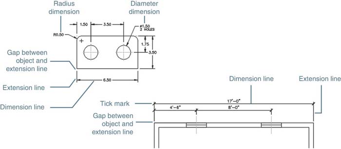
Figure 8-3
Dimension lines: On mechanical drawing, lines between extension lines that end with arrowheads and include numerical dimensional values located within the lines. On architectural drawings, lines between extension lines that end with tick marks and include numerical dimensional values above the lines. Dimension lines are normally parallel to the object or distance they describe.
Extension lines: Lines that extend away from an object and allow dimensions to be located off the surface of an object. Extension lines are normally perpendicular to the object or distance being dimensioned. There is a small gap between an extension line and an object, and an extension line usually extends slightly beyond the dimension line.
Leader lines: Lines drawn at an angle, not horizontally or vertically, that are used to dimension specific shapes such as holes. The starting point of a leader line includes an arrowhead. Numerical values are drawn at the end opposite the arrowhead.
Linear dimensions: Dimensions that define the straight-line distance between two points.
Angular dimensions: Dimensions that define the angular value, measured in degrees, between two straight lines.
Radial dimensions: Dimensions that define the radius or diameter of an arc or a circle.
Some Dimensioning Conventions
Standard rules in drafting apply to dimensions as well as everything else. Standardization makes drawings easier to read by others and is essential in creating any kind of drafting documentation. Here are some conventions in dimensioning (see Figure 8-4):
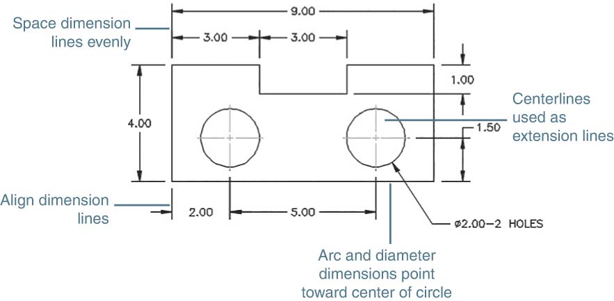
Figure 8-4
Dimension lines are drawn evenly spaced; that is, the distance between dimension lines is uniform. A general rule of thumb is to locate dimension lines about 1/2 inch, or 15 millimeters, apart.
There should be a noticeable gap between the edge of a part and the beginning of an extension line. This serves as a visual break between the object and the extension line. The visual difference between the linetypes is emphasized by using different lineweights for the two types of lines.
A leader line in a radius or diameter dimension defines the size of a hole and should be positioned so that the arrowhead points toward the center of the hole.
Centerlines may be used as extension lines. No gap is used when a centerline is extended beyond the edge lines of an object.
Dimension lines should be aligned whenever possible to give a drawing a neat, organized appearance.
Some Common Errors to Avoid
Dimensioning is complicated, and the rules can take some getting used to. Figure 8-5 shows a few common errors to avoid:

Figure 8-5
Avoid crossing extension lines. Place longer dimensions farther away from the object than shorter dimensions.
Do not locate dimensions within cutouts; always use extension lines.
Do not locate any dimension too close to an object. Dimension lines should be at least 1/2 inch, or 15 millimeters, from the edge of the object.
Avoid long extension lines. Locate dimensions in the same general area as the feature being defined.
8-3 Linear Dimensions
The Linear dimension tool is used to create horizontal and vertical dimensions.
Creating a Linear Dimension
Create basic linear dimensions with the Linear dimension tool. Linear dimensions can be horizontal or vertical, depending on where you drag the crosshairs to place the dimension line. Select the extension line locations or origins to create linear dimensions.
Select Linear on the Dimensions panel of the Annotate tab (Figure 8.6).

Figure 8-6
Command: _dimlinear
Specify first extension line origin or <select object>:
Select the starting point for the first extension line.
Specify second extension line origin:
Select the starting point for the second extension line.
[MText Text Angle Horizontal Vertical Rotated]:
Locate the dimension line by moving the crosshairs to the desired location.
Press the left mouse button to place the dimension.
The dimension text locations shown in Figure 8-7 are the default setting locations. The location and style can be changed using the Dimension Style command discussed in Section 8-4.
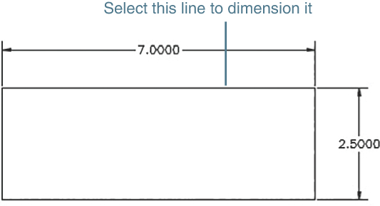
Figure 8-7
Creating a Vertical Dimension
The vertical dimension shown in Figure 8-7 was created using the same procedure demonstrated for the horizontal dimension, except that different extension line origin points were selected. AutoCAD automatically switches from horizontal to vertical dimension lines as you move the cursor around an object.
If there is confusion between horizontal and vertical lines when adding dimensions—that is, if you don’t seem to be able to generate a vertical line—type V and press Enter in response to the following prompt:
[MText Text Angle Horizontal Vertical Rotated]:
AutoCAD now draws vertical dimension lines.
Creating a Horizontal Dimension by Selecting the Object to Be Dimensioned
If you are dimensioning a specific object rather than a distance between objects, you can select the object directly to dimension it (Figure 8-7).
Select Linear from the Dimensions panel.
Command: _dimlinear

Specify first extension line origin or <select object>:
Right-click.
Select object to Dimension:
Select the line to be dimensioned.
This option allows you to select the distance to be dimensioned directly. The option applies only to horizontal and vertical lengths. Aligned dimensions, although linear, are created by using the Aligned tool.
Changing the Default Dimension Text Using the Text Option
AutoCAD automatically creates a text value for a given linear distance. A different value or additional information can be added, as described next (Figure 8-8).

Figure 8-8
Select Linear from the Dimensions panel.
Command: _dimlinear

Specify first extension line origin or <select object>:
Select the starting point for the first extension line.
Specify second extension line origin:
Select the starting point for the second extension line.
[MText Text Angle Horizontal Vertical Rotated]:
Type t and press Enter.
Enter dimension text <7.50>:
The value given is the linear value of the distance selected. In this example, more information is required, so the default distance value must be modified. To retain the true distance in the dimension, type open and closed angle brackets (<>) where the true distance should go.
Type 5 × 1.50 (<>) and press Enter.
The additional information appears as part of the dimension text.
Note
AutoCAD uses a pair of closed angle brackets to indicate where the true text should go. If you do not add the angle brackets, the entire dimension value will be replaced with what you type. If you want a blank dimension with no text, enter T for the text option, press the Spacebar, and then place the dimension.
Changing the Default Dimension Text with the Mtext Option
Select Linear from the Dimensions panel.
Command: _dimlinear

Specify first extension line origin or <select object>:
Select the starting point for the first extension line.
Specify second extension line origin:
Select the starting point for the second extension line.
[MText Text Angle Horizontal Vertical Rotated]:
Type m and press Enter.
The Text Editor contextual tab appears (Figure 8-9). The text value appears in a box below the Text Editor tab. To remove the existing text, highlight the text and press the Delete key. You can then type new text into the box. In the example shown, by typing %%P<>, the default value of 9.50 was replaced with a plus/minus symbol followed by the true distance value returned by the angle brackets.

Figure 8-9
You can add information before or after the default text by placing the cursor in the appropriate place and typing the additional information.
You can edit the dimension text in the same way as you edited regular drawing text (refer to Section 2-15). Figure 8-10 shows the Font drop-down menu. To access the available fonts, double-click the dimension text to display the Text Editor contextual tab. In the Formatting panel, click the arrow next to the Font name.
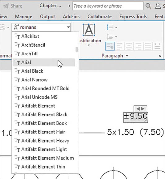
Figure 8-10
Figure 8-11 shows the text Color option that can be used to change the color of text.

Figure 8-11
Editing an Existing Dimension
Figure 8-12 shows a figure with an existing 7.00 - 2 PLACES dimension.

Figure 8-12
Click the existing dimension.
Blue grips appear on the dimension text, the arrows, and the definition points of the dimension.
Move the cursor away from the figure, right-click, and select Quick Properties.
The Quick Properties mini-palette appears.
Click the Text override box and highlight the dimension text value 7.00 - 2 PLACES.
Enter the new text value. In this example, enter <>%%P0.05.
The closed angle brackets indicate the true distance value. The ± sign is created by typing two percent symbols and the letter P (%%P).
Close the Quick Properties palette by pressing the Esc key.
Figure 8-13 shows the edited dimension.

Figure 8-13
You can also edit dimension text in the Properties palette. Open the Properties palette by clicking a dimension, right-clicking one of the grips, and selecting Properties. Scroll down the palette to Text override and enter the new values (Figure 8-13).
Note
You can also access the Text Editor by double-clicking the existing dimension.
8-4 Dimension Styles
The Dimension Style Manager establishes the dimension styles that control the appearance and format of dimensions. Open the Dimension Style Manager by clicking the arrow in the lower-right corner of the Dimensions panel of the Annotate tab (Figure 8-14).
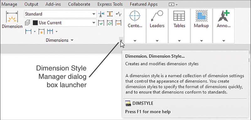
Figure 8-14
A great variety of dimension styles are used to create technical drawings. The differences in styles may be the result of different drawing conventions. For example, when following North American conventions, architects locate dimensions above the dimension lines, and mechanical engineers locate dimensions within the dimension lines. AutoCAD works in decimal units, whether millimeters or inches are assumed, so parameters set for inches are not usable for millimeter drawings. The Dimension Style Manager allows you to conveniently choose and set dimension parameters that suit your particular drawing requirements.
Figure 8-15 shows the Dimension Style Manager dialog box. Open the Dimension Style Manager by clicking its dialog box launcher, the arrow at the right end of the Dimensions panel title.
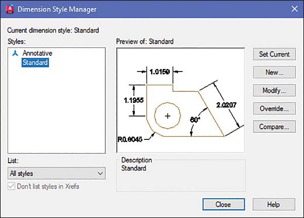
Figure 8-15
This section explains how to use the Modify option to change the Standard style settings to suit a specific drawing requirement. The Set Current, New, Override, and Compare options are used to create new custom dimension styles designed to meet specific applications. Click Modify... on the first screen of the Dimension Style Manager to begin. Figure 8-16 shows the Primary Units tab of the Modify Dimension Style: Standard dialog box.

Figure 8-16
Changing the Scale of a Drawing
Drawings are often drawn to scale because a part is either too big to fit on a sheet of drawing paper or too small to be seen. For example, a microchip circuit must be drawn at several thousand times its actual size in order to be seen.
Drawing scales are written according to the following formats:
SCALE: 1 = 1
SCALE: FULL
SCALE: 1000 = 1
SCALE: .25 = 1
In each example, the value on the left indicates the scale factor. A scale factor value greater than 1 indicates that the drawing is larger than actual size. A scale factor value less than 1 indicates that the drawing is smaller than actual size.
Regardless of the drawing scale selected, the dimension values must be the true measure. Figure 8-17 shows the same rectangle drawn at two different scales. The top rectangle is drawn at a scale of 1 = 1, or its true size. The bottom rectangle is drawn at a scale of 2 = 1, or twice its true size. In both examples, the 3.00 dimension remains the same.
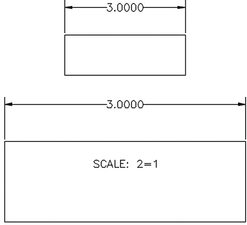
Figure 8-17
The Scale factor edit box on the Primary Units tab of the Modify Dimension Style: Standard dialog box is used to change the dimension values to match different drawing scales. Figure 8-18 shows the measurement scale set to a factor of 0.5000. If the drawing scale is 2 = 1, as shown in Figure 8-17, then the scale factor for Measurement scale must be 0.5000. Compare the preview in Figure 8-16 with the preview in Figure 8-18, in which the scale factor has been changed.
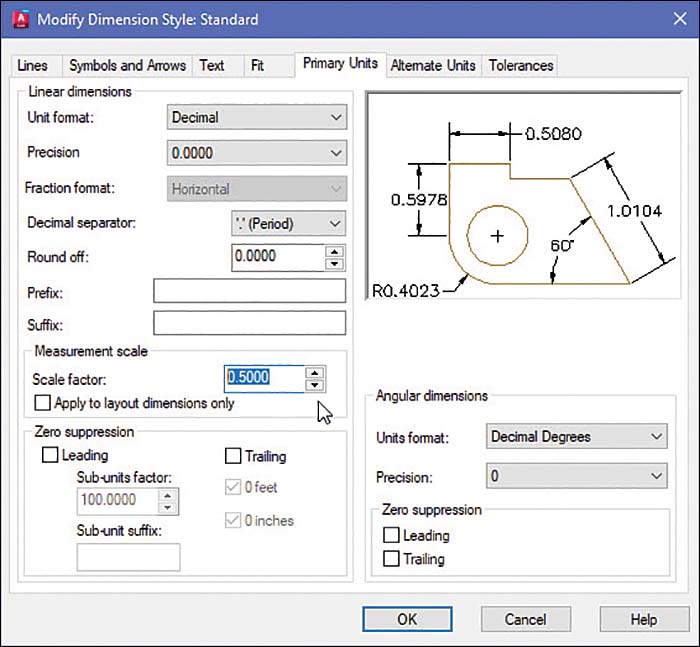
Figure 8-18
Using the Text Tab
Figure 8-19 shows the Text tab of the Modify Dimension Style: Standard dialog box. You can use this tab to change the height of dimension text or the text placement. In Figure 8-20, the text height is changed from the default value of 0.1800 to the new value 0.3000. The preview box shows the resulting changes in both the text and how it will be positioned on the drawing.
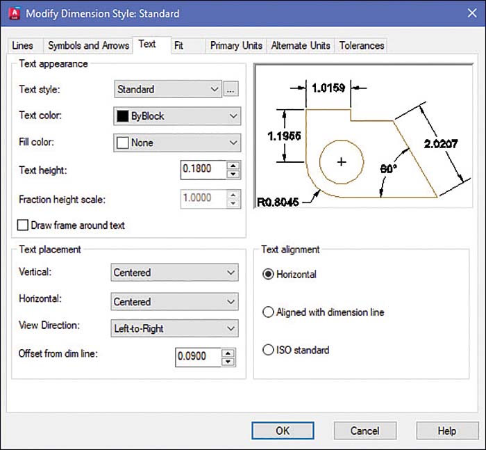
Figure 8-19

Figure 8-20
Figure 8-21 shows text located above the dimension. This change was created using the Vertical drop-down list in the Text placement area.

Figure 8-21
Figure 8-22 shows text aligned with the direction of the dimension lines in accordance with ISO (International Organization for Standardization) standards. This change was made by clicking the ISO standard radio button in the Text alignment area. Note that dimensions in this book are created in compliance with ANSI (American National Standards Institute) standards.
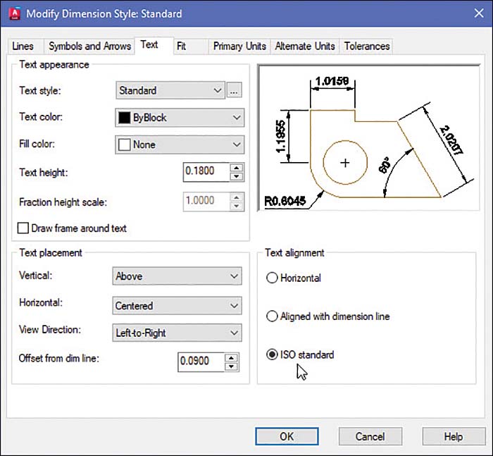
Figure 8-22
8-5 Units
It is important to understand that dimension values are not the same as the mathematical units defined in the Drawing Units dialog box (refer to Section 1-7). Dimension values are manufacturing instructions and always include a tolerance, even if the tolerance value is not stated. Manufacturers use a predefined set of standard dimensions that are applied to any dimension value that does not include a written tolerance. Standard tolerance values vary from organization to organization.
Figure 8-23 shows a chart of standard tolerances.

Figure 8-23
In Figure 8-24, a distance is dimensioned twice: once as 2.75 and a second time as 2.7500. Mathematically, these two values are equal, but they are not equal according to the same manufacturing instruction. The 2.75 value could, for example, have a standard tolerance of ±0.01, whereas the 2.7500 value could have a standard tolerance of ±0.0005. A tolerance of ±0.0005 is more difficult and therefore more expensive to manufacture than a tolerance of ±0.01.
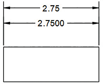
Figure 8-24
Figure 8-25 shows examples of units expressed in millimeters, decimal inches, and architectural units. A zero is not required to the left of the decimal point for decimal inch values less than one. Millimeter values do not require zeros to the right of the decimal point. Architectural units should always include the foot (′) and inch (″) symbols. Millimeter and decimal inch values never include symbols; the units are defined in the title block of a drawing.

Figure 8-25
Preventing a Zero from Appearing to the Left of the Decimal Point
Open the Dimension Style Manager by clicking the arrow in the lower-right corner of the Dimensions panel of the Annotate tab.
Click Modify.
The Modify Dimension Style: Standard dialog box appears.
Select the Primary Units tab (Figure 8-26).

Select the Leading checkbox in the Zero suppression area.
A check mark appears in the box, indicating that the function is on.
Click OK and then Close to return to the drawing.
Save the change, if desired. You can now dimension using any of the dimension commands, and no zeros will appear to the left of the decimal points. Figure 8-27 shows the results.

Figure 8-27
Changing the Number of Decimal Places in a Dimension Value
Open the Dimension Style Manager by clicking the arrow in the lower-right corner of the Dimensions panel of the Annotate tab.
Click Modify.
The Modify Dimension Style: Standard dialog box appears.
Select the Primary Units tab.
Click the arrow to the right of the Precision drop-down list.
A list of precision options cascades down (Figure 8-28).
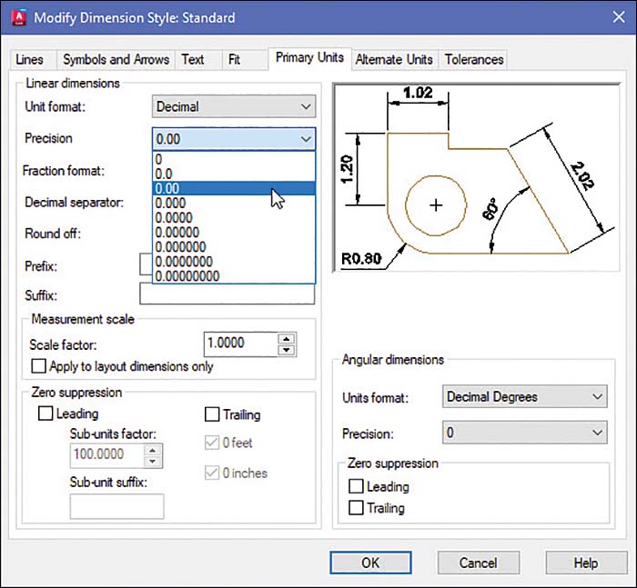
Figure 8-28
Select the desired precision.
Save the changes, if desired. You can now dimension using any of the dimension commands, and the resulting values will be expressed with the selected precision.
8-6 Aligned Dimensions
Aligned dimensions are a particular form of linear dimensions that must be created with the Aligned dimension tool. Aligned dimensions are created by selecting an object or picking a distance. The resulting dimension line will be parallel with the object or selected points (Figures 8-29 and 8-30).

Figure 8-29

Figure 8-30
Creating an Aligned Dimension
On the Dimensions panel of the Annotate tab, click the down arrow beside the Linear tool and select Aligned.
Command: _dimaligned

Specify first extension line origin or <select object>:
Select the first extension line origin point.
Specify second extension line origin:
Select the second extension line origin point.
[Mtext Text Angle]:
Select the location for the dimension line.
Figure 8-30 shows an aligned dimension with the dimension text aligned with the dimension line.
Using Text Options
Select Aligned from the Linear flyout on the Dimensions panel.
Command: _dimaligned

Specify first extension line origin or <select object>:
Press Enter.
Select object to dimension:
Select the line.
[Mtext Text Angle]:
Select the dimension line location.
A response of M to the prompt line in step 3 activates the Multiline Text tool (refer to Section 2-15). The Text option can be used to replace or supplement the default text generated by AutoCAD.
A response of A to the prompt in step 3 activates the Angle option. The Angle option allows you to change the angle of the text within the dimension line.
8-7 Radius and Diameter Dimensions
Figure 8-31 shows an object that includes both arcs and circles. The general rule is to dimension arcs with radius dimensions and circles with diameter dimensions. This convention is consistent with the tooling required to produce the feature shape. Any arc greater than 180° is considered a circle and is dimensioned by using a diameter.
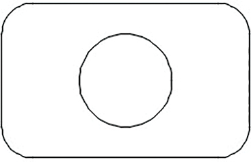
Figure 8-31
Creating a Radius Dimension
On the Dimensions panel of the Annotate tab, click the down arrow beside the Linear tool and select Radius.
Command: _dimradius
Select arc or circle:
Select the arc to be dimensioned.
Specify dimension line location or [Mtext Text Angle]:
Position the radius dimension so that its leader line is neither horizontal nor vertical.
Figure 8-32 shows the resulting dimension. The dimension text can be altered by clicking the text. The Multiline Text Editor appears (Figure 8-33). Highlight the existing text and type in the new text. Close the text editor and press the Esc key.

Figure 8-32

Figure 8-33
Altering the Default Dimension
Double-click the dimension.
The dimension is enclosed in a shaded box.
Press the Delete key to remove the existing dimension.
Add the desired text or type in the new dimension.
Click the mouse.
Figure 8-34 shows the resulting dimension. The Radius dimension tool automatically includes a center mark with the dimension. The center mark can be excluded from the dimension as described next.

Figure 8-34
Removing the Center Mark from a Radius Dimension
Open the Dimension Style Manager by clicking the arrow in the lower-right corner of the Dimensions panel of the Annotate tab.
Click Modify.
The Modify Dimension Style: Standard dialog box appears.
Select the Symbols and Arrows tab.
In the Center marks area, select the None radio button (Figure 8-35).

Figure 8-35
Click OK to return to the drawing.
The radius dimension automatically updates to the new dimension style setting. Figure 8-36 shows the result.
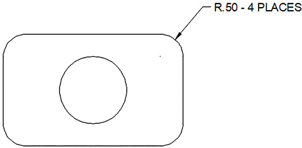
Figure 8-36
Creating a Diameter Dimension
You can create a dimension substyle—that is, a new style that applies to only one dimension type. In this case, you would like centerlines on diameter dimensions but no center marks at all on radius dimensions. Create the new dimension style for diameter dimensions only as follows (see Figure 8-37):
Open the Dimension Style Manager.
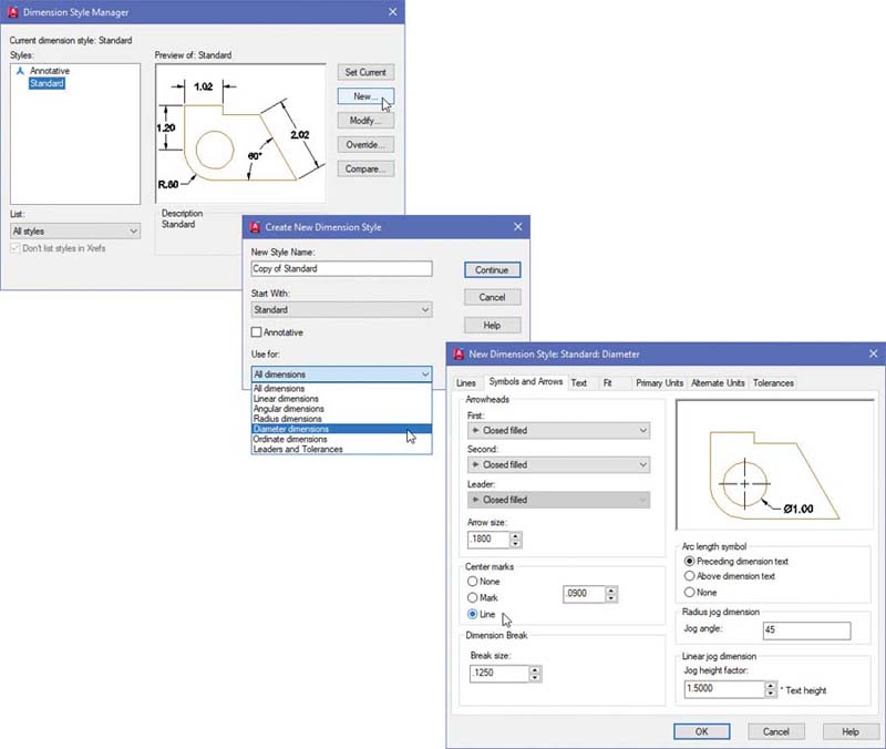
Figure 8-37
Click New.
The Create New Dimension Style dialog box appears.
Leave New Style Name setting as is. Under Use for, click the down arrow and select Diameter dimensions. Click Continue.
AutoCAD creates a new substyle called Diameter under the Standard dimension style. The New Dimension Style: Standard Diameter dialog box appears.
Select the Symbols and Arrows tab.
In the Center marks area, select the Line radio button. Click OK.
The Dimension Style Manager lists Diameter as a new substyle within the Standard dimension style.
Click Close.
Creating Center Marks and Lines
The Symbols and Arrows tab of the Modify Dimension Style dialog box presents three options for indicating the center of an existing circle. You can specify None (no marks), Mark (a small cross at the center of the circle), or Line (the small cross plus horizontal and vertical lines that extend beyond the circumference of the circle).
You can configure AutoCAD to automatically add center marks or horizontal and vertical centerlines as follows:
On the Dimensions panel of the Annotate tab, click the down arrow beside the Linear tool and select Diameter.
Command: _dimdiameter

Select arc or circle:
Select the circle.
Specify dimension line location or [MText Text Angle]:
Locate the dimension away from the object so that the leader line is neither horizontal nor vertical.
Adding Linear Dimensions to Given Centerlines
Select Linear from the Dimension tool on the Dimensions panel.
Command: _dimlinear

Specify first extension line origin or <select object>:
Select the lower endpoint of the circle’s vertical centerline.
Specify second extension line origin:
Select the endpoint of the vertical edge line (the endpoint that joins with the corner arc).
Figure 8-38 shows the results.

Figure 8-38
Repeat steps 1–3 to add the vertical dimension needed to locate the circle’s center point.
Add the overall dimensions, using the Linear dimension tool.
Figure 8-39 shows the result. Radius and diameter dimensions are usually added to a drawing after the linear dimensions because they are less restricted in their locations. Linear dimensions are located close to the distance that they are defining, whereas radius and diameter dimensions can be located farther away and use leader lines to identify the appropriate arc or circle.
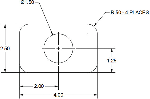
Figure 8-39
Avoid crossing extension and dimension lines with leader lines (Figure 8-40).

Figure 8-40
Note
The diameter symbol Ø can be added when creating text by typing %%c. The characters %%c start appearing in the Text Editor window but are converted to the diameter symbol Ø as soon as you type the letter c.
8-8 Angular Dimensions
Figure 8-41 shows four possible angular dimensions that you can create using the Angular dimension tool, which is a flyout from the Dimension tool on the Dimensions panel. The extension lines and degree symbol are added automatically.

Figure 8-41
Creating an Angular Dimension
Follow the steps below to dimension the object in Figure 8-42.

Figure 8-42
Select Angular from the Dimension tool on the Dimensions panel.
Command: _dimangular

Select arc, circle, line, or <specify vertex>:
Select the short vertical line on the lower-right side of the object.
Select second line:
Select the slanted line.
Specify dimension arc line location [MText Text Angle]:
Locate the text away from the object.
Figure 8-43 shows the result.
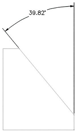
Figure 8-43
Note
It is considered best practice to use two extension lines for angular dimensions and to avoid having the arrowhead touch the surface of a part.
Note
The degree symbol is added automatically when you create an angular dimension. You can add the degree symbol to regular text by typing %%d.
Avoiding Overdimensioning
Figure 8-44 shows a shape dimensioned by using an angular dimension. The shape is completely defined. Any additional dimension would be an error. It is tempting, in an effort to make sure that a shape is completely defined, to add more dimensions, such as a horizontal dimension for the short horizontal edge at the top of the shape. This dimension is not needed, though, and adding it is considered double dimensioning (see Chapter 9, Section 9-10).

Figure 8-44
8-9 Ordinate Dimensions
Ordinate dimensions are dimensions based on an X,Y coordinate system. Ordinate dimensions do not include extension or dimension lines or arrowheads; they have simple horizontal and vertical leader lines drawn directly from the features of the object. While standard dimensions indicate the distances between points or objects, ordinate dimensions denote the distance each object is from the origin point. Ordinate dimensions are particularly useful when dimensioning an object that includes many small holes.
Figure 8-45 shows an object that is to be dimensioned using ordinate dimensions. Ordinate dimensions are automatically calculated from the X,Y origin or, in this example, the lower-left corner of the screen. If the object had been drawn with its lower-left corner on the origin, you could proceed directly to the Ordinate tool, which is a flyout from the Dimension tool on the Dimensions panel. However, the lower-left corner of the object in Figure 8-45 is not located on the origin.

Figure 8-45
Moving the Origin and the Origin Icon
To move the origin and the origin icon, you first move the origin to the corner of the object and then use the Ordinate dimension tool (Figure 8-46).
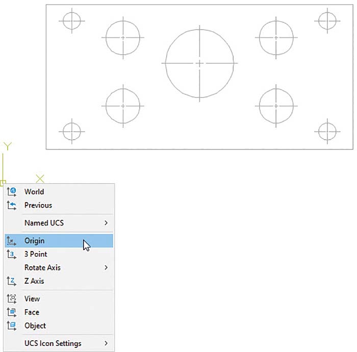
Figure 8-46
Move the cursor onto the origin icon.
Right-click and select the Origin option.
The cursor becomes attached to the origin.
Move the origin to the desired location.
Click the mouse (Figures 8-47 and 8-48).

Figure 8-47
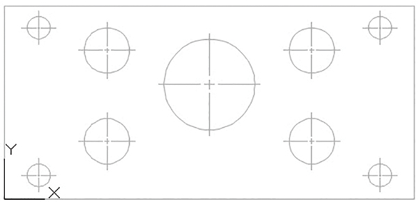
Figure 8-48
Adding Ordinate Dimensions to an Object
The following procedure assumes that you have already used the Dimension Style Manager (refer to Section 8-4) to set the desired dimension style and that you have moved the origin to the lower-left corner of the object, as just described.
Click the Ortho Mode button in the status bar at the bottom of the screen.
Select the Ordinate tool flyout from the Dimension tool on the Dimensions panel (Figure 8-49).

Figure 8-49
Command: _dimordinate
Select feature location:
Select the lower endpoint of the first circle’s vertical centerline.
Specify leader endpoint or [Xdatum Ydatum MText Text Angle]:
Select a point along the X axis directly below the vertical centerline of the circle.
The ordinate value of the point is added to the drawing. This point should have a 0.50 value. The text value may be modified by using either the MText or Text option or by using the Dimension Style Manager dialog box to define the precision of the text.
Right-click to restart the command and dimension the object’s other features.
Extend the centerlines across the object and add the diameter dimensions for the holes.
Once the ordinate dimensioning is complete, you can return the UCS icon from the corner of the object to the origin of the drawing.
Click the UCS icon at the corner of the object to display the grips.
Hover the mouse over the intersection of the X and Y axes (do not click the grip) and, in the shortcut menu that appears, click World.
Figure 8-49 shows the completed drawing. The Text option of the prompt shown in step 3 can be used to modify or remove the default text value.
8-10 Baseline Dimensions
Baseline dimensions are a series of dimensions that originate from a common baseline or datum line. Baseline dimensions are very useful because they help eliminate tolerance buildup associated with chain-type dimensions.
The Baseline tool can be used only after an initial dimension has been drawn. AutoCAD defines the first extension line origin of the initial dimension selected as the baseline for all baseline dimensions.
Using the Baseline Dimension Tool
Figure 8-50 shows the same object from Section 8-9, this time dimensioned using Baseline dimensions. You do not need to move the UCS as you do with ordinate dimensions. When you use baseline dimensions, the origin of the first point chosen is understood.
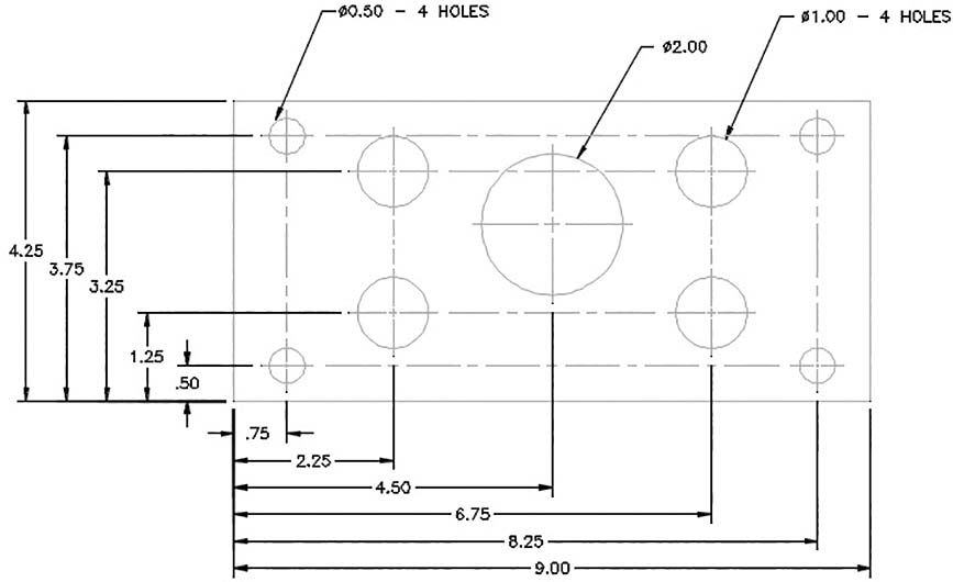
Figure 8-50
Select the Linear tool flyout from the Linear tool on the Dimensions panel.
Command: _dimlinear

Specify first extension line origin or <select object>:
Select the upper-left corner of the object.
This selection determines the baseline.
Specify second extension line origin:
Select the endpoint of the first circle’s vertical centerline.
Specify dimension line location or [Text Angle Horizontal Vertical
Rotated]:
Select a location for the dimension line.
Command:
Select the Baseline tool from the Dimensions panel.
Specify a second extension line origin or [Undo Select] <Select>:
Select the endpoint of the next circle’s vertical centerline.
Specify a second extension line origin or [Undo Select] <Select>:
Continue to select the circle centerlines until all circles are located.
Specify a second extension line origin or [Undo Select] <Select>:
Select the upper-right corner of the object.
Right-click and select the Enter option.
This ends the Baseline dimension command.
Repeat steps 1–9 for the vertical baseline dimensions. Remember to start with an existing vertical dimension.
Add the circles’ diameter values.
Figure 8-50 shows the completed drawing. The Baseline dimension option can also be used with the Angular dimension option.
8-11 Continued Dimensions
The Continue tool on the Dimensions panel creates chain dimensions based on an initial linear, angular, or ordinate dimension.
The second extension line’s origin becomes the first extension line origin for the continued dimension.
Using the Continue Dimension Command
Figure 8-51 shows a continuous string of chain dimensions, created using Continue.

Figure 8-51
Select the Linear tool flyout from the Dimension tool on the Dimensions panel.
Command: _dimcontinue

Specify first extension line origin or <select object>:
Select the upper-left corner of the object.
Specify second extension line origin:
Select the right endpoint of the uppermost horizontal line.
Dimension line location (Text Angle Horizontal Vertical Rotated):
Select a dimension line location.
Command:
Select the Continue tool from the Dimensions panel.
Command: _dimcontinue

Specify a second extension line origin or [Undo Select] <Select>:
Select the next linear distance to be dimensioned.
Specify a second extension line origin or [Undo Select] <Select>:
Continue selecting features to the dimension string until the object’s horizontal edges are completely dimensioned.
AutoCAD automatically aligns the dimensions. Figure 8-52 shows how the Continue tool dimensions distances that are too small for both the arrowhead and dimension value to fit within the extension lines.

Figure 8-52
8-12 Quick Dimension
Use the Quick dimension tool to add a series of dimensions (Figure 8-53).
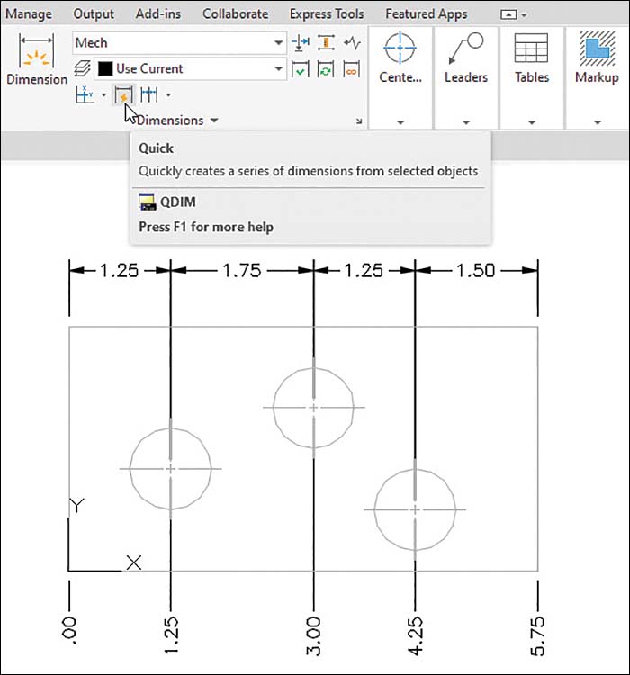
Figure 8-53
Using the Quick Dimension Tool
Select the Quick tool from the Dimensions panel.
Command: _qdim

Select geometry to dimension:
Window select the entire object to be dimensioned—in this example, the rectangle and the three circles—and press Enter.
Specify dimension line position, or [Continuous Staggered Baseline
Ordinate Radius Diameter datumPoint Edit seTtings]<Baseline>:
Right-click.
Specify dimension line position, or [Continuous Staggered Baseline
Ordinate Radius Diameter datumPoint Edit seTtings]<Baseline>:
Choose a dimension type, such as Continuous, from the right-click menu.
In the example in Figure 8-53, the Quick dimension tool was run twice. Continuous was chosen for the top dimension string, and Ordinate was used for the bottom string (after the UCS icon was moved to the desired origin).
Position the dimension lines, right-click, and enter the position.
Notice that the extension lines start from the centers of the circles. You can select the dimensions and drag their extension lines to the endpoints of the centerlines to make a drawing clearer.
8-13 Center Mark
When AutoCAD first draws a circle or an arc, a guideline appears from the center mark; however, as soon as you pick or enter a radius, the circle no longer shows a center mark. Figure 8-54 shows the Circle command in process, a completed circle with no center mark, and a circle with centerlines added with the Center Mark tool.

Figure 8-54
Adding Centerlines to a Given Circle
Open the Dimension Style Manager by clicking the arrow in the lower-right corner of the Dimensions panel of the Annotate tab.
Click Modify.
The Modify Dimension Style: Standard dialog box appears.
Select the Symbols and Arrows tab.
In the Center marks area, select the Line radio button.
The preview display shows a horizontal centerline and a vertical centerline.
Click OK and then Close to return to the drawing.
Select the Center Mark tool from the Dimensions panel.
Select arc or circle:
Select the circle.
Horizontal and vertical centerlines appear. The size of the center mark can be controlled by using the Size edit box in the Center marks area. If the centerline’s size appears to be unacceptable, try different sizes until you get an acceptable size.
8-14 Mleader and Qleader
Leader lines are slanted lines that extend from notes or dimensions to specific features or locations on the surface of a drawing. A leader line usually ends with an arrowhead or a dot. The Radius and Diameter tools, which are flyouts from the Dimension tool on the Dimensions panel, automatically create leader lines. The Multileader and Quick Leader tools can add leader lines to drawing notations not associated with radius or diameter dimensions. Quick Leader creates two objects: a leader line and a text or multiline text object.
Creating a Quick Leader
Type qleader at the command prompt.
Command: _qleader

Specify first leader point, or [Settings]<Settings>:
Select the starting point for the leader line.
This is the point at which the arrowhead appears. In the example shown in Figure 8-55, the upper-right corner of the object is selected.
Specify next point:

Figure 8-55
Select the location of the endpoint of the slanted line segment.
Specify next point:
Draw a short horizontal line segment and press Enter.
Specify text width <0.0000>:
Press Enter.
Enter first line of annotation text <MText>:
Press Enter.
Use the cursor to extend the text box as needed.
Type the desired text (Figure 8-56).

Figure 8-56
Click OK.
The text appears next to the horizontal line segment of the leader line.
Drawing a Curved Leader Line
The Quick Leader tool is used to draw curved leader lines and leader lines that end with dots (Figure 8-57).

Figure 8-57
Type qleader in response to a command prompt.
Command: _qleader

Specify first leader point, or [Settings] <Settings>:
Type s and press Enter.
The Leader Settings dialog box appears (Figure 8-58).

Figure 8-58
Select the Leader Line & Arrow tab.
Select the Spline option in the Leader Line area and then click OK.
Specify first leader point, or [Settings] <Settings>:
Select the starting point for the leader line.
The arrowhead appears.
Specify next point:
Select the next point.
Select next point:
AutoCAD shifts to Drag mode, allowing you to move the cursor around and watch the leader line change shape. You can select more than one point to define the shape.
Complete the leader line, as explained previously.
Drawing a Leader Line with a Dot at Its End
In this example, a leader is created with the Multileader command. The current multileader style is modified to use a dot rather than an arrowhead.
Click the arrow in the lower-right corner of the Leaders panel of the Annotate tab.
The Multileader Style Manager dialog box appears (Figure 8-59).

Figure 8-59
Click Modify.
The Modify Multileader Style: Standard dialog box appears (Figure 8-59).
Click the arrow on the right end of the Symbol box in the Arrowhead area and select the Dot option.
Click OK.
Select Multileader on the Leaders panel of the Annotate tab.
Select an arrowhead location and a leader landing location and then enter text in the Text Editor edit box.
Click anywhere in the drawing area to complete the multileader.
8-15 Text Angle
The Text Angle tool is used to change the angle of existing dimension text.
Changing the Angle of Dimension Text
Select the Text Angle tool from the Dimensions panel.
Select dimension:
Select the dimension text.
Select new location for dimension or [Left Right Center Home
Angle]: _a

Specify angle for dimension text:
Type 90 and press Enter (Figure 8-60).

Figure 8-60
8-16 Tolerances
Tolerances are numerical values assigned with the dimensions that define the limits of manufacturing acceptability for a distance. AutoCAD can create four types of tolerances: symmetrical, deviation, limits, and basic (Figure 8-61). A company may also use a group of standard tolerances that are applied to any dimensional value that is not assigned a specific tolerance (refer to Figure 8-23). Tolerances for numerical values expressed in millimeters are applied using a convention different from the convention used for inches. (Tolerances are discussed in Chapters 9 and 10. The dimensioning tools are also covered in those chapters.)

Figure 8-61
8-17 Dimensioning Holes
Holes are dimensioned by stating their diameter and depth, if any. The symbol Ø is used to represent diameter. It is considered good practice to dimension a hole by using a diameter value because the tooling used to produce the hole is also defined in terms of diameter values. A notation like 12 DRILL is considered less desirable because it specifies a machining process. Manufacturing processes should be left, whenever possible, to the discretion of the shop.
Dimensioning Individual Holes
Figure 8-62 shows three different methods that can be used to dimension a hole that does not go completely through an object. If a hole goes completely through, only the diameter needs to be specified. The Radius and Diameter dimension tools are covered in Section 8-7. Depth values may be specified by modifying the default text using Text override in the Properties or Quick Properties palette, as described in Section 8-3.

Figure 8-62
Figure 8-63 shows two methods of dimensioning holes in sectional views. The single-line note version on the left is the preferred method.

Figure 8-63
Dimensioning Hole Patterns
Figure 8-64 shows two different hole patterns dimensioned. The circular pattern includes the note Ø10 – 4 HOLES. This note serves to define all four holes within the object.
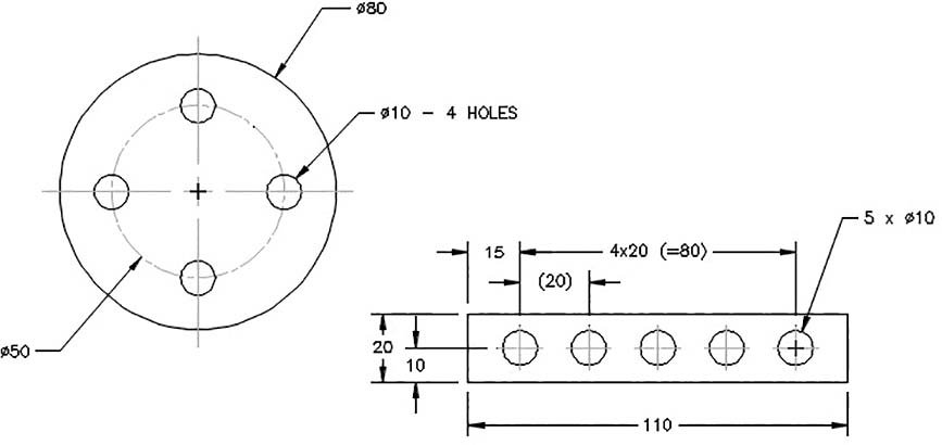
Figure 8-64
Figure 8-64 also shows a rectangular object that contains five holes of equal diameter, equally spaced from one another. The notation 5 × Ø10 specifies five holes of 10 diameter. The notation 4×20 (=80) means 4 equal spaces of 20. The notation (=80) is a reference dimension and is included for convenience. Reference dimensions are explained in Chapter 9, Section 9-10.
Figure 8-65 shows two additional methods for dimensioning repeating hole patterns. Figure 8-66 shows a circular hole pattern that includes two different hole diameters. The hole diameters are not noticeably different from one another and could be confused. One group is defined by indicating letter A; the other is dimensioned in a normal manner.
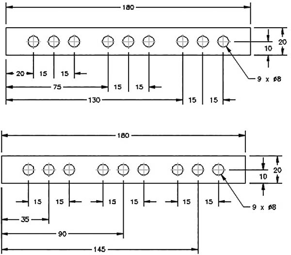
Figure 8-65

Figure 8-66
8-18 Placing Dimensions
There are several general rules concerning the placement of dimensions (Figure 8-67):
Place dimensions near the features that they are defining.
Do not place dimensions on the surface of an object.
Align and group dimensions so that they are neat and easy to understand.
Avoid crossing extension lines. Sometimes it is impossible not to cross extension lines because of the complex shape of the object, but whenever possible, avoid crossing extension lines.
Place shorter dimensions closer to the object than longer ones.
Always place overall dimensions the farthest away from the object.
Do not dimension the same distance twice. Doing so is called double dimensioning. Double dimensioning is discussed in Chapter 9, Section 9-10.
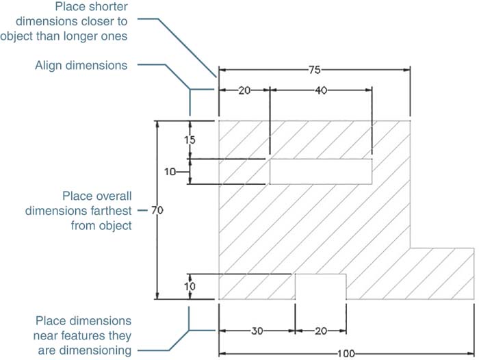
Figure 8-67
8-19 Fillets and Rounds
Fillets and rounds may be dimensioned individually or by using a note. In many design situations, all of the fillets and rounds are the same size, and a note like the one shown in Figure 8-68 is used. Any fillets or rounds that have a different radius from that specified by the note are dimensioned individually.

Figure 8-68
See Section 2-26 in Chapter 2 for an explanation of how to draw fillets and rounds using the Fillet command.
8-20 Rounded Shapes—Internal
Internal rounded shapes are called slots. Figure 8-69 shows three different methods of dimensioning slots. The end radii are indicated by the note R - 2 PLACES, but no numerical value is given. The width of the slot is dimensioned, and it is assumed that the radius of the rounded ends is exactly half of the stated width.
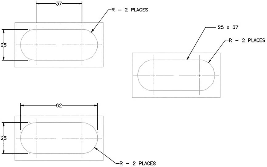
Figure 8-69
Note
You can use AutoCAD’s Fillet command to make a 180° arc by selecting two parallel lines. The arc radius will be precisely half the distance between the lines.
8-21 Rounded Shapes—External
Figure 8-70 shows three examples of shapes with external rounded ends. As with internal rounded shapes, the end radii are indicated, but no value is given. The width of the object is given, and the radius of the rounded end is assumed to be exactly half of the stated width.

Figure 8-70
The second example in Figure 8-70 is an object dimensioned using the object’s centerlines. This type of dimensioning is used when the distance between the holes is more important than the overall length of the object—that is, when the tolerance for the distance between the holes is more exact than the tolerance for the overall length of the object.
The overall length of the object is given as a reference dimension (100). This means that the object will be manufactured on the basis of other dimensions, and the 100 value will be used only for reference.
Objects with partially rounded edges should be dimensioned as shown in Figure 8-70. The radii of the end features are dimensioned. The center point of the radii is implied to be on the object centerline. The overall dimension is given; it is not referenced unless specific radius values are included.
8-22 Irregular Surfaces
There are three different methods for dimensioning irregular surfaces: tabular, baseline, and baseline with oblique extension lines. Figure 8-71A shows an irregular surface dimensioned using the tabular method. In Figure 8-71B, the curve points are defined using baseline dimensions with the extension lines of one dimension obliqued for clarity. The X,Y axes are defined by using the edges of the object. Points are then defined relative to the X,Y axes. The points are assigned reference numbers, and the reference numbers and X,Y coordinate values are listed in chart form, as shown.

Figure 8-71
Figure 8-72 shows an irregular curve fully dimensioned with baseline dimensions. The baseline method references all dimensions back to specified baselines. There are usually two baselines: one horizontal and one vertical.

Figure 8-72
It is considered poor practice to use a centerline as a baseline. Centerlines are imaginary lines that do not exist on an actual object, and having a centerline as a baseline would make it more difficult to manufacture and inspect the finished objects.
Baseline dimensioning is very common because it helps eliminate tolerance buildup (see Section 9-11) and is easily adaptable to many manufacturing processes. AutoCAD has a special Baseline dimension tool for creating baseline dimensions.
8-23 Polar Dimensions
Polar dimensions are similar to polar coordinates. A location is defined by a radius (distance) and an angle. Figure 8-73 shows an object that includes polar dimensions. The holes are located on a circular centerline, and their positions from the vertical centerline are specified by angles.

Figure 8-73
Figure 8-74 shows an example of a hole pattern dimensioned by using polar dimensions.
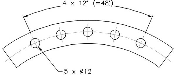
Figure 8-74
8-24 Chamfers
Chamfers are angular cuts made on the edges of objects. They are usually used to make it easier to fit two parts together. They are most often made at 45° angles but may be made at any angle. Figure 8-75 shows two objects with chamfers between surfaces 90° apart and two examples between surfaces that are not 90° apart. Either of the two types of dimensions shown for the 45° dimension can be used. If an angle other than 45° is used, the angle and setback distance must be specified.
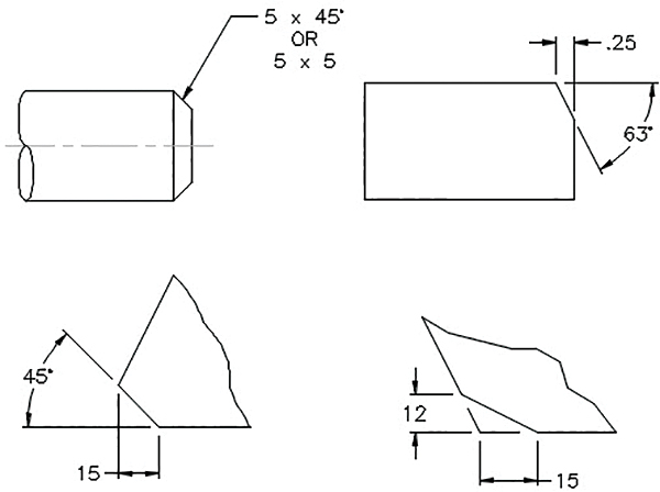
Figure 8-75
Figure 8-76 shows two examples of internal chamfers. Both of them define the chamfers by using an angle and a diameter. Internal chamfers are very similar to countersunk holes (refer to Chapter 5, Section 5-26).
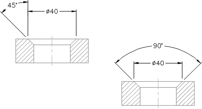
Figure 8-76
8-25 Knurling
Knurls are used to make it easier to grip a shaft or to roughen a surface before it is used in a press fit. There are two types of knurls: diamond and straight.
Knurls are defined by their pitch and diameter (Figure 8-77). The pitch of a knurl is the ratio of the number of grooves on the circumference to the diameter. Standard knurling tools sized to a variety of pitch sizes are used to manufacture knurls for both English and metric units.
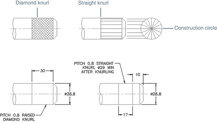
Figure 8-77
Diamond knurls may be represented by using a double-hatched pattern or by an open area with notes. Use the Hatch command with the ANSI37 pattern to draw the double-hatched lines. (Hatching is covered in Section 6-4.)
Straight knurls may be represented using straight lines in the pattern shown in Figure 8-77 or using an open area with notes. The straight-line pattern is created by projecting lines from a construction circle. The construction points are evenly spaced on the circle. Once drawn, the straight-line knurl pattern can be wblocked for use on other drawings. See Section 3-22 for an explanation of Wblock.
8-26 Keys and Keyseats
Keys are small pieces of material used to transmit power. For example, Figure 8-78 shows how a key can be fitted between a shaft and a gear so that the rotary motion of the shaft can be transmitted to the gear.

Figure 8-78
There are many different key styles. The key shown in Figure 8-78 has a rectangular cross section and is called a square key. Keys fit into grooves called keyseats, or keyways.
Keyseats are dimensioned from the bottom of the shaft, or hole, as shown.
8-27 Symbols and Abbreviations
Symbols in dimensioning help accurately display the meaning of each dimension. Symbols also help eliminate language barriers when reading drawings. Figure 8-79 lists a number of dimensioning symbols and their meanings. The height of a symbol should be the same as the text height.
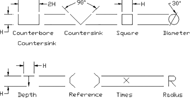
Figure 8-79
Abbreviations should be used on drawings very carefully. Whenever possible, write out the full word, including correct punctuation. Figure 8-80 shows several standard abbreviations used on technical drawings.

Figure 8-80
8-28 Symmetry and Centerline
An object is symmetrical about an axis when one side is an exact mirror image of the other. Figure 8-81 shows a symmetrical object. The symbol comprising two short parallel lines or the note OBJECT IS SYMMETRICAL ABOUT THIS AXIS (centerline) can be used to designate symmetry.

Figure 8-81
If an object is symmetrical, only half of the object needs to be dimensioned. The other dimensions are implied by the symmetry note or symbol.
A centerline is slightly different from the axis of symmetry. An object may or may not be symmetrical about its centerline (Figure 8-81). Centerlines are used to define the center of both individual features and entire objects. Use the centerline symbol when a line is a centerline but do not use it in place of the symmetry symbol.
8-29 Dimensioning to Points
Curved surfaces can be dimensioned by using theoretical points (Figure 8-82). There should be a small gap between the surface of an object and the lines used to define a theoretical point. The point should be defined by the intersection of at least two lines.
There should also be a small gap between the extension lines and the theoretical point used to locate the point.
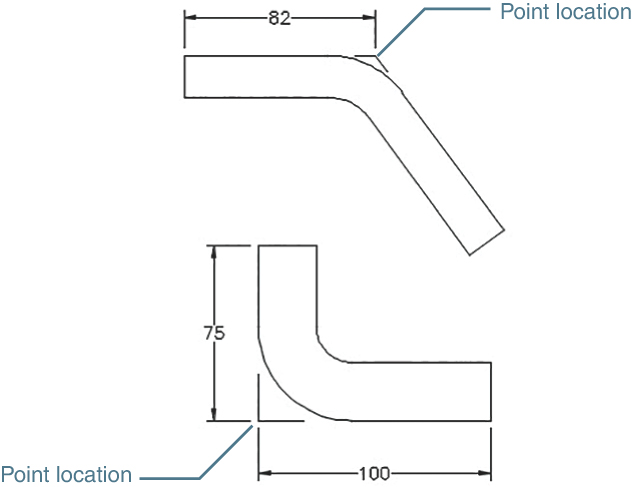
Figure 8-82
8-30 Coordinate Dimensions
Coordinate dimensions are used for objects that contain many holes. Baseline dimensions can also be used, but when there are many holes, baseline dimensions can create a confusing appearance and require a large area on the drawing. Coordinate dimensions use charts that simplify the appearance, use far less space on the drawing, and are easy to understand.
Figure 8-83 shows an object that has been dimensioned with coordinate dimensions rather than dimension lines. Holes are identified on the drawing by letters. Holes of equal diameter use the same letter. The hole diameters are presented in chart form.

Figure 8-83
Hole locations are defined by a series of centerlines referenced to baselines. The distance from the baseline to the centerline is written below the centerline, as shown.
Figure 8-84 shows an object that has been dimensioned using coordinate dimensions in tabular form. Each hole is assigned both a letter and a number. Holes of equal diameter are assigned the same letter. A chart defines the diameter values for the hole letters.

Figure 8-84
Hole locations are defined relative to X,Y axes. A Z axis is used for depth dimensions. A chart lists each hole by its letter – number designation and specifies its distance from the X, Y, or Z axis. The overall dimensions are given by using extension and dimension lines.
The side view in Figure 8-84 does not show any hidden lines because if all of the lines were shown, it would be too confusing to understand. A note such as THIS VIEW LEFT BLANK FOR CLARITY may be added to such a drawing.
8-31 Sectional Views
Sectional views are dimensioned (Figure 8-85). The sectional lines should be drawn at an angle that allows the viewer to clearly distinguish between sectional lines and extension lines.

Figure 8-85
8-32 Orthographic Views
Like sectional views, orthographic views are also dimensioned. Add dimensions to orthographic views where the features appear in contour. Holes should be dimensioned in their circular views. Figure 8-86 shows three views of an object that has been fully dimensioned.
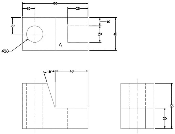
Figure 8-86
The hole dimensions are added to the top view, where the hole appears circular. The slot is also dimensioned in the top view because it appears in contour. The slanted surface is dimensioned in the front view.
The height of surface A is given in the side view rather than run along extension lines across the front view. The length of surface A is given in the front view. This is a contour view of the surface.
It is good practice to keep dimensions in groups. Doing so makes it easier for the viewer to find dimensions.
Be careful not to double dimension a distance. A distance should be dimensioned only once per view. If a 30 dimension were added above the 25 dimension on the right-side view, it would be an error. The distance would be double dimensioned: once with the 25 + 30 dimension and again with the 55 overall dimension. The 25 + 30 dimensions are mathematically equal to the 55 overall dimension, but there is a distinct difference in how they affect the manufacturing tolerances. Double dimensions are explained more fully in Chapter 9.
Figure 8-87 shows an object dimensioned from its centerline. This type of dimensioning is used when the distances between the holes relative to one another are critical.

Figure 8-87
8-33 Very Large Radii
Some radii are so large that it is not practical to draw the leader for the radius dimension at full size. Figure 8-88 shows an example of an object that uses foreshortened leader lines.

Figure 8-88
Creating a Radius for Large Radii
Click the Jogged tool on the Dimensions panel.
Select arc or circle:
Click the large arc.
Specify center location override:
Select a center point for the dimension.
The point selected is not the arc’s true center point, as that is probably off the screen. The Jogged tool overrides the true center point location and substitutes the one selected (Figure 8-88).
Right-click and select Enter.
Select a text location by moving the cursor and then clicking the left mouse button.
Add a center mark to the end of the leader line.
8-34 Exercise Problems
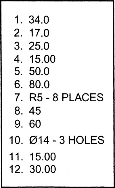
Redraw the shapes shown in Exercise Problems EX 8-1 through EX 8-6. Locate the dimensions and tolerances as shown.
EX8-1 Inches

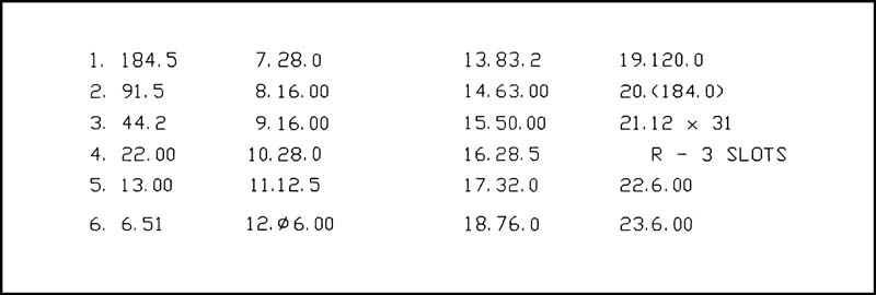
EX8-2 Millimeters

EX8-3 Millimeters

EX8-4 Inches


EX8-5 Millimeters


EX8-6 Millimeters

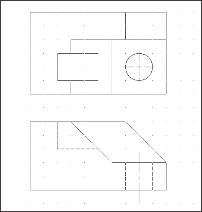
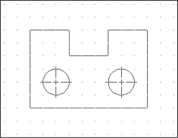
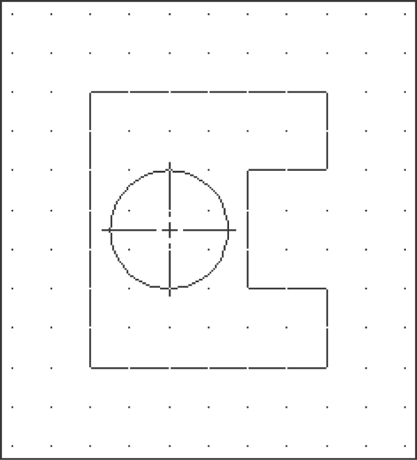
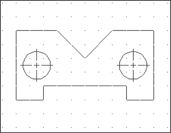
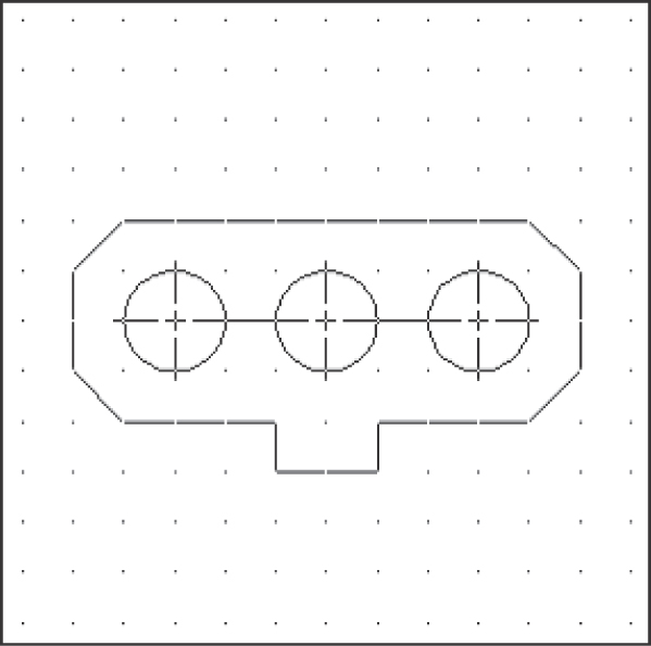
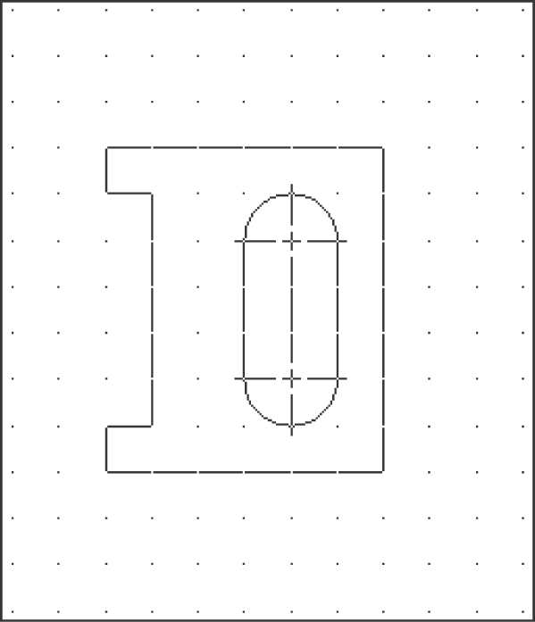
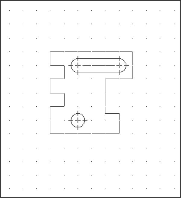
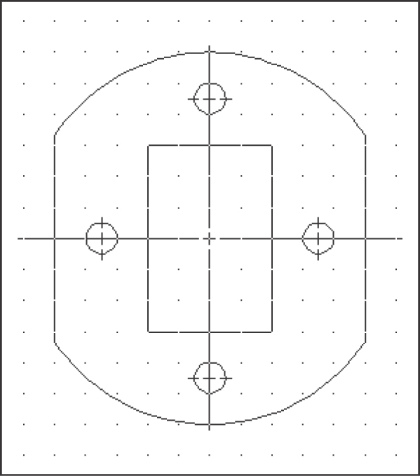
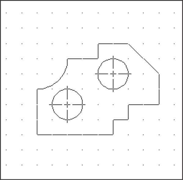
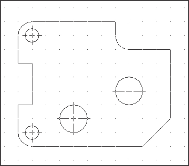
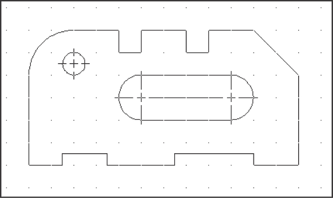
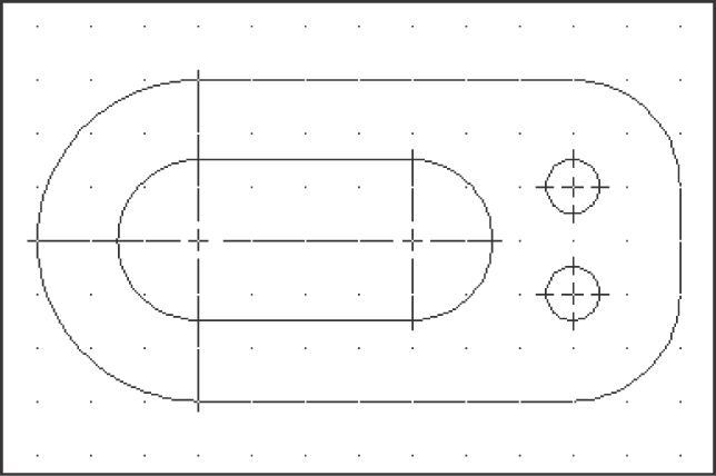
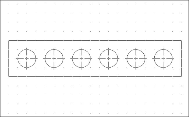
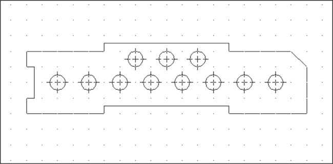
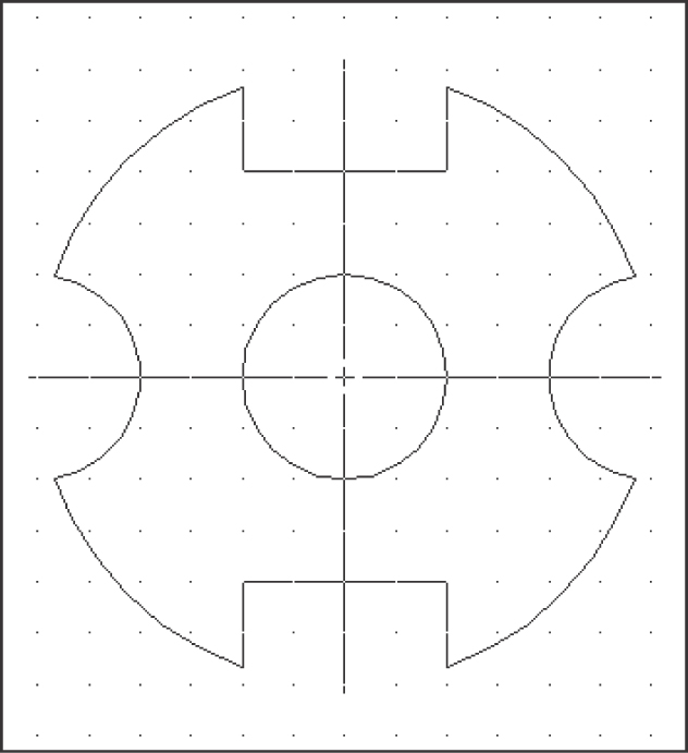
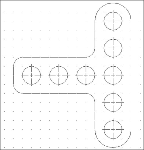
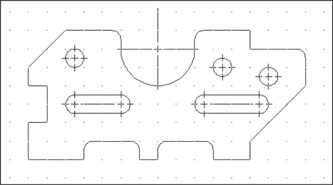
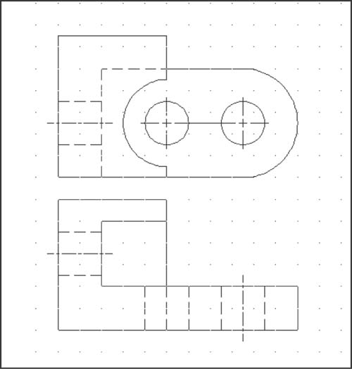
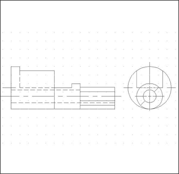
Measure and redraw the shapes in Exercise Problems EX 8-7 through EX 8-53. Add the appropriate dimensions. Specify the units and scale of the drawing. The dotted grid background has either 0.50-inch or 10-millimeter spacing.
EX8-7
EX8-8
EX8-9
EX8-10

EX8-11

EX8-12
EX8-13
EX8-14

EX8-15

EX8-16

EX8-17

EX8-18
EX8-19

EX8-20

EX8-21

EX8-22
EX8-23

EX8-24

EX8-25

EX8-26
EX8-27

EX8-28

EX8-29

EX8-30
EX8-31

EX8-32
EX8-33
EX8-34

EX8-35
EX8-36

EX8-37
EX8-38

EX8-39
EX8-40

EX8-41

EX8-42
EX8-43

EX8-44

EX8-45

EX8-46
EX8-47

EX8-48

EX8-49

EX8-50

EX8-51
EX8-52
EX8-53