
Chapter 12
Working Drawings
12-1 Introduction
This chapter explains how to create assembly drawings, parts lists, and detail drawings. It includes guidelines for titles, revisions, tolerances, and release blocks. This chapter shows how to create a design layout and then use the design layout to create assembly and detail drawings with the Layer command.
12-2 Assembly Drawings
An assembly drawing shows how objects fit together (Figure 12-1). All information necessary to complete an assembly must be included on the assembly drawing. This information may include specific assembly dimensions, torque requirements for bolts, finishing and shipping instructions, and any other appropriate company or customer specifications.
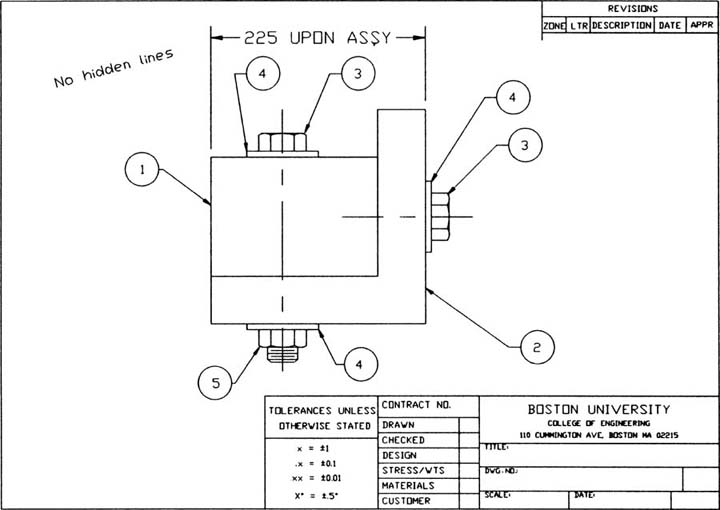
Figure 12-1
An assembly drawing may be called a top drawing because it is the first of a series of drawings used to define a group of parts that are to be assembled together. Such a group of drawings, referred to as a family of drawings, may include subassemblies, modification drawings, detail drawings, and a parts list (Figure 12-2).

Figure 12-2
Assembly drawings do not contain hidden lines. A sectional view may be used to show internal areas that are critical to the assembly. Specific information about the internal surfaces of objects that make up the assembly can be found on the detail drawings of the individual objects (Figure 12-3).

Figure 12-3
Each part of an assembly is identified by an assembly, or item, number. An assembly number is enclosed in a circle or an ellipse, and a leader line is drawn between the assembly number and the part. Assembly numbers are unique to each assembly drawing; that is, a part that is used in several different assemblies may have a different assembly number on each assembly drawing.
If several of the same part are used in the same assembly, each part should be assigned the same assembly number. A leader line should be used to identify each part unless the differences between the parts are obvious. In Figure 12-4, the difference between head sizes for the fasteners is obvious, so all parts need not be identified.

Figure 12-4
Assemblies should be shown in their natural, or neutral, positions. Figure 12-5 shows a clamp in a slightly open position. It is best to show the clamp jaws partially open rather than fully closed or fully open. In general, a drawing should show an assembly in its most common position.
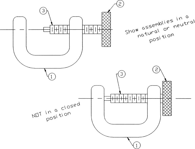
Figure 12-5
The range of motion for an assembly is shown by the use of phantom lines. In Figure 12-6, note how the range of motion for the hinged top piece is displayed by using phantom lines.

Figure 12-6
12-3 Drawing Formats (Templates)
Figure 12-7 shows a general format for an assembly drawing. The format varies from company to company and with the size of the drawing paper.

Figure 12-7
Adding a Drawing Template
AutoCAD includes many different drawing templates that conform to ANSI and ISO standards. A template automatically includes a drawing border, a title block, a revision block, and a partial release block.
Click the Application Menu button in the top-left corner of the AutoCAD window, click New, and click Drawing.
The Select template dialog box appears (Figure 12-8).
Select the Tutorial-iMfg template and click Open.

Figure 12-8
A new, unsaved drawing using the selected template appears on the screen (Figure 12-9). Drawing geometry in previous chapters has been created in model space, the infinitely large, three-dimensional drawing and modeling environment. When you need to create a drawing, you switch to paper space and create your drawing layout.
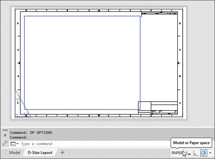
Figure 12-9
Figure 12-9 shows identifiers for the current space. The triangular UCS icon in the lower-left corner of the drawing area indicates paper space, and represents 2D space only.
At the left end of the status bar, tabs let you select model space or a paper space drawing layout. When you start a new drawing with acad.dwt or acadiso.dwt, there are two layout tabs: Layout1 and Layout2. In the drawing template Tutorial-iMfg, one layout tab has been deleted, and the other has been renamed D-Size Layout. Finally, the MODEL/PAPER status bar button tells you which space you are in.
Figure 12-10 shows a completed title block for an iMfg template. It was completed using the Text tool, located on the Annotate tab. An A-size drawing sheet is 8.5 × 11 inches. If an A-size template is selected, the screen units are automatically fitted to the sheet size and are in inches. (A list of standard drawing sheet sizes is included in Section 1-8. Standard metric drawing sheet sizes are also listed in Section 1-8.)

Figure 12-10
The closest equivalent to an A-size inch drawing is an A4-size drawing, which is 210 × 297 millimeters. Figure 12-11 shows the Select template dialog box set to select a Tutorial-mMfg template. The screen units are millimeters.
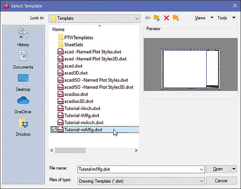
Figure 12-11
12-4 Title Block
A title block is located in the lower-right corner of a drawing and includes the drawing’s name and number, the company’s name, the drawing scale, the release date of the drawing, and the sheet number of the drawing. Other information may be included as well. Figure 12-12 shows a sample title block created from an iMfg template. The text was added using the Multiline Text tool and positioned using the Move tool.

Figure 12-12
Figure 12-13 shows the title block from an mMfg template. The title block appears with a series of XXX inputs. Use the Explode command located on the Modify panel of the Home tab to explode the title block.


Figure 12-13
To replace the XXX inputs with words, erase the XXX and replace them with the appropriate names and numbers.
Drawing Titles (Names)
A drawing title should clearly define the function of the part. It should be presented using the following word sequence:
Noun, modifier, modifying phrase (optional)
For example:
SHAFT, HIGH SPEED, LEFT HAND
GASKET, LOWER
The noun in a title may consist of two words if normal usage includes the two words. For example:
GEAR BOX, COMPOSITE
SHOCK ABSORBER, LEFT
Drawing Numbers
Drawing numbers are assigned by companies according to their usage requirement. Numbering systems vary greatly. Drawing numbers are usually recorded in a log book or an online register to prevent duplication of numbers.
Company Name
The company’s name and logo are preprinted on drawing paper or are included as a block so that they can be inserted on each drawing.
Scale
Define the scale of the drawing.
When the drawing size is the same as the object size, define the scale as follows:
SCALE: FULL, or 1 = 1
When the drawing size is twice as large as the object size, the scale is defined like this:
SCALE: 2 = 1
When the drawing size is half as large as the object size, the scale is defined as follows:
SCALE: 1 = 2
Release Date
A drawing is released only after all persons required by the company’s policy to review it have reviewed it and added their signatures to the release block. Once released, a drawing becomes a legal document. Drawings that have not been officially released are often stamped with a statement such as “NOT RELEASED” or “FOR REFERENCE ONLY.” Stamps are usually created in AutoCAD and saved to a hard drive or network drive so they can be reused in other drawings. Stamps would be removed when a drawing is released.
Sheet
The number of the sheet relative to the total number of sheets that make up the drawing should be stated clearly. For example:
SHEET 2 OF 3
or
SH 2 OF 3
12-5 Revision Block
Drawings used in industry are constantly being changed. Products are improved or corrected, and drawings must be changed to reflect and document these changes. Figure 12-14 shows a sample revision block.

Figure 12-14
Drawing changes are listed in the revision block by letter. A revision block is located in the upper-right corner of a drawing (refer to Figure 12-7). Figure 12-15 shows a revision block from an mMfg template. The text was added with Mtext, and the lines were added with Line.
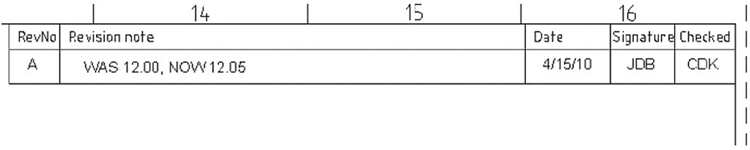
Figure 12-15
Each drawing revision is listed by letter in the revision block. A brief description of the change is also included. It is important that the description be as accurate and complete as possible. Revisions are often used to check drawing requirements on parts manufactured before the revisions were introduced.
The revision letter is also added to the field of the drawing in the area where the change was made. The letter is located within a “flag” to distinguish it from dimensions and drawing notes. The flag serves to notify anyone reading the drawing that revisions have been made.
Most companies have systems in place that allow engineers and designers to quickly make changes to drawings. These change orders are called engineering change orders (ECOs), change orders (COs), or engineering orders (EOs), depending on the company’s preference. Change orders are documented on special drawing sheets that are usually stapled to a print of the drawing. Figure 12-16 shows a change order attached to a drawing.
After a group of change orders accumulates, the change orders are incorporated into the drawing. This process, called a drawing revision, is different from a revision to the drawing. A drawing revision is usually indicated by a letter located somewhere in the title block. Revision letters may be included as part of the drawing number or in a separate box in the title block. Whenever you are working on a drawing, make sure that you have the latest revision and all appropriate change orders. Companies have recording and referencing systems for listing all drawing revisions and drawing changes.

Figure 12-16
12-6 Tolerance Block
Most drawings include a tolerance block next to the title block, which lists the standard tolerances that apply to the dimensions on the drawing. A dimension that does not include a specific tolerance is assumed to have the appropriate standard tolerance.
Figure 12-17 shows a sample tolerance block for inch values, and Figure 12-18 shows a sample tolerance block for millimeter values. In Figure 12-17, the dimension 2.00 has an implied tolerance of ±.01. In Figure 12-18, the 20.0 dimension has an implied tolerance of ±0.1.
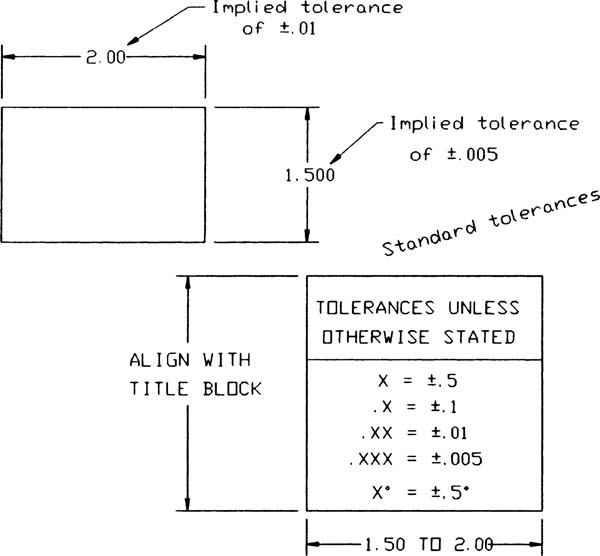
Figure 12-17
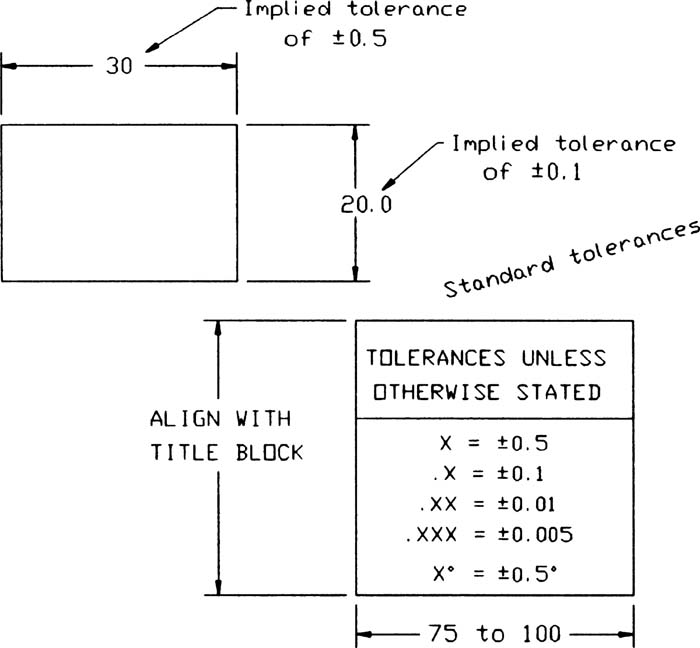
Figure 12-18
12-7 Release Block
A release block contains a list of approval signatures or initials required before a drawing can be released for production (Figure 12-19). The required signatures are generally as follows:

Figure 12-19
Drawn—The person who created the drawing.
Checked—The person or department that checked the drawing. Drawings are checked for errors and compliance with company procedures and conventions. Some large companies have checking departments, whereas smaller companies have drawings checked by a senior person or the drafting supervisor.
Design—The engineer in charge of the design project. The designer and the drafter may be the same person.
Stress/Wts—The department or person responsible for the stress analysis of the design.
Materials—Usually, a person in the production department checks the design and makes sure that the necessary materials and the machine times for the design are available. This person may also schedule production time.
Customer—The customer for the design may have a representative on site at the production facility to check that its design requirements are being met. For example, it is not unusual for the Air Force to assign an officer to a plant that manufactures its fighter aircraft.
12-8 Parts List (Bill of Materials [BOM])
A parts list is a list of all parts used on an assembly. The parts list in Figure 12-20 was created using the Table tool (see Section 2-27). The terms parts list and bill of materials are interchangeable (Figure 12-21).

Figure 12-20
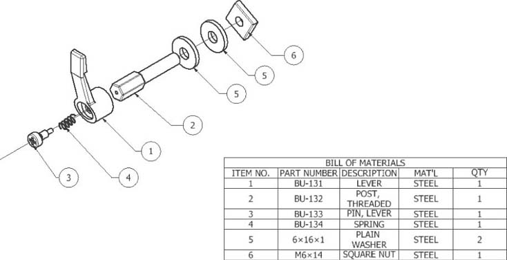
Figure 12-21
A parts lists may be located on an assembly drawing above the title block or on a separate drawing sheet. An assembly drawing made with AutoCAD may include the parts list on a separate layer within the drawing. Use only uppercase letters on a parts list.
Figure 12-22 shows two sample parts list formats, including dimensions. Parts list formats vary greatly from company to company. The dimensions are given in inches. They may be converted to millimeters by the conversion factor 1.00 inch = 25.4 millimeters. The AutoCAD template includes a parts list format that is automatically sized to the sheet size.

Figure 12-22
A parts list provides a way to cross-reference detail drawing numbers to assembly item numbers. It also provides a list of the materials needed for production and is very helpful for scheduling and materials purchasing.
Parts purchased from a vendor and used exactly as they are supplied, without any modification, do not have detail drawings but are included on the parts list. The washers, bolts, and screws listed on the parts list shown in Figure 12-21 would not have detail drawings. This means that the information on the parts list must be sufficient for a purchaser to know exactly what size washers, bolts, and screws to buy. The information used to define an object on the drawing, the drawing callout, is also used on the parts list. See Chapter 11 for an explanation of drawing callouts for fasteners.
12-9 Detail Drawings
A detail drawing is a drawing of a single part. The drawing should include all information necessary to accurately manufacture the part, including orthographic views with all appropriate hidden lines, dimensions, tolerances, material requirements, and any special manufacturing requirements. Figure 12-23 shows a sample detail drawing.
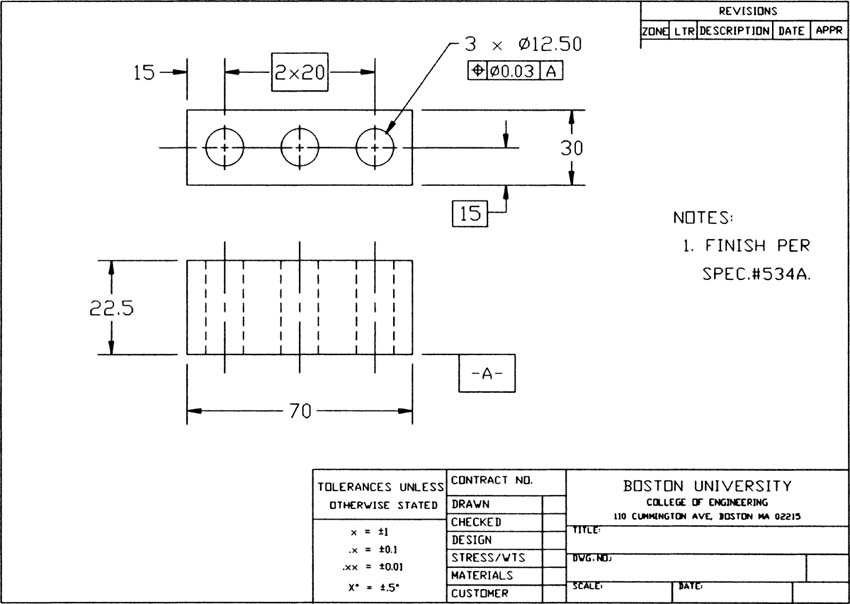
Figure 12-23
Detail drawings include title, release, tolerance, and revision blocks located on the drawing in the same places they are found on assembly drawings.
12-10 First-Angle Projection
The instructions for the creation of orthographic views as presented in this book are based on third-angle projection (see Section 5-36 in Chapter 5). Third-angle projection is used in the United States, Canada, and Great Britain, among other countries. Many other countries such as Japan use first-angle projection to create orthographic views.
Figure 12-24 shows an object and the orthographic views of the object created in first-angle projection. Note that the top view in the first-angle projection is the same as the top view in the third-angle projection, but it is located below the front view rather than above the front view, as in the third-angle projection. Right-side views are also the same but are located to the left of the front view in first-angle projections and to the right in third-angle projections.

Figure 12-24
Many companies now do business internationally. A company may have manufacturing plants in one country and assembly plants in another. Drawings can be prepared in several different countries. It is important to indicate on a drawing whether first-angle or third-angle projections are being used. Figure 12-25 shows the SI (International System of Units) symbols for first-angle projections. The SI symbol is included on a drawing in the lower-right corner above the title block, as shown in Figure 12-24.

Figure 12-25
12-11 Drawing Notes
Drawing notes are used to provide manufacturing information that is not visual—for example, finishing instructions, torque requirements for bolts, and shipping instructions.
Drawing notes are usually located above the title block on the right side of the drawing (Figure 12-26). Drawing notes are listed by number. If a note applies to a specific part of the drawing, the note number is enclosed in a triangle. The note numbers enclosed in triangles are also drawn next to the corresponding areas of the drawing.

Figure 12-26
12-12 Design Layouts
A design layout is not the same as a drawing layout. It is like a visual calculation sheet used to size and locate parts as a design is developed. A design layout allows you to “build the assembly” on paper.
When drawings are created on a drawing board, an initial design layout is made to locate and size the parts. Then the individual detail drawings and the assembly drawing are created from the layout.
The same procedure can be followed with AutoCAD. First, create a design layout on one layer and then either transfer the individual parts and assembly drawing to other layers or create a new drawing from the design layout drawing by using the Save As command.
The drawing problem in the next section demonstrates how to create a design layout and then use it to create the required detail and assembly drawings.
12-13 Drawing Problem
Figure 12-27 shows an engineer’s sketch for a design problem. Prepare an assembly drawing and a detail drawing of the PN123 base and PN124 center plate on the basis of the following information:
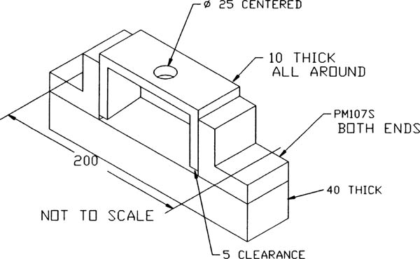
Figure 12-27
The part PM107S end brackets are existing parts and can be used as is. Figure 12-28 shows a detail drawing of PM107S.

Figure 12-28
Place the mounting holes for the two end brackets 200 millimeters apart, as shown in the engineer’s sketch in Figure 12-28.
Establish the size of the base so that it aligns with the end brackets and is 40 millimeters thick.
Determine the size for the center bracket so that it just fits between the end plates and has a 25-millimeter-diameter hole centered in its top surface. The center bracket should extend 10 millimeters above the end brackets and 5 millimeters above the base. The center bracket should be 10 millimeters thick all around.
Mount the end brackets to the base, using M12 flat head screws, and attach the end brackets to the center bracket by M20 bolts with appropriate nuts.
Use only standard-length fasteners.
Creating the Design Layout
Follow the steps below and refer to Figure 12-29 to create the design layout of the part.
Draw horizontal and vertical lines that define the top of the base and the distance between the mounting holes in the end brackets.
Draw front and top views of the end brackets, using the vertical lines drawn in step 1. The vertical lines should align with the centerlines of the mounting holes.
Draw the base 40 millimeters thick.
Size the center brackets.

Figure 12-29
Note that at this stage of the design layout, all lines are drawn according to the same pattern. Lines can be changed to hidden lines or centerlines when the detail and assembly drawings are created.
Add the M12 flat head screws. A length of 20 millimeters is chosen from the tables in the online Appendix. The threaded holes in the base are M12 to match the screws. The tap drill size is included on the layout for reference.
Add the M20 × 60 bolts and nuts.
The bolt length is determined by adding 25 (end bracket) + 10 (center bracket) + 15 (nut thickness = .75D) + 2 thread pitches = 52 millimeters. The next-largest standard bolt length, as listed in the online Appendix, is 60, so an M20 × 60 bolt is specified.
The diameter of the clearance holes is chosen as 14 and 22 and is listed on the design layout.
The design layout is complete. It may be used to create the required assembly drawing and detail drawings in one of two ways: by using the Layer command and including all of the drawings under one file name or by using the Save As command to create separate drawings.
Creating a Drawing Using Layers
Depending on the visibility setting of each layer, when lines are moved from one layer to another, the lines are removed from the original layer. The design layout may be preserved by first making a copy of it, or that part of the design layout that you wish to transfer, and then using the copy for the transfers.
To make a copy of the layout, use the Copy command. Select all the drawing geometry and then select a base point. Select exactly the same point as the second point of displacement, and AutoCAD copies the layout exactly over itself. You can then move the appropriate lines to different layers.
Create a detail drawing of the base by transferring the base from the design layout. Respond to the prompts as follows.
Copy the layout onto itself.
COMMAND:_Copy
Select objects:
Window the entire layout and press Enter.
<Base point or displacement>/Multiple:
Select a point on the screen.
Second point of displacement:
Type @ and press Enter.
You must select exactly the same point as in step 3. Entering the @ symbol tells AutoCAD to use the previous point.
Create the following layers (see Section 3-23):
ASSEMBLY
END
END-DIM
BASE
BASE-DIM
CENTER
CENTER-DIM
PARTSLIST
The “DIM” layers will be used for the dimensions for the detail drawings. This will allow the dimensions to be shut off if they are not needed.
Transfer the base to a layer called BASE. Turn off all of the other layers. The resulting transfer should look like Figure 12-30.
It is difficult to make a perfectly clean transfer—that is, a transfer of only the lines of the base. If other lines appear on the transferred base, erase and trim them as necessary.
Move the views closer together, if necessary.
Turn on the BASE-DIM layer and make it the current layer. Add the appropriate dimensions, tolerances, and callouts.
Create the drawing format and add the necessary information (drawing title, etc.).
The title block and so forth may be saved as a block or as part of a prototype drawing. Figure 12-31 shows the resulting drawing.

Figure 12-30

Figure 12-31
Creating a Drawing from a Layout
Figure 12-32 shows an assembly drawing that was created from the design layout. The procedure is as follows:
Save the design layout.
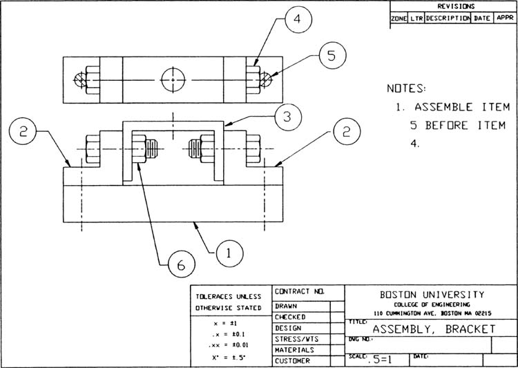
Figure 12-32
Create the assembly drawing from the design layout drawing but use the Save As command to save it under a different drawing name.
Add the appropriate drawing sheet format and notes.
Save the assembly drawing, using its new name.
Figure 12-33 shows a parts list for the assembly.
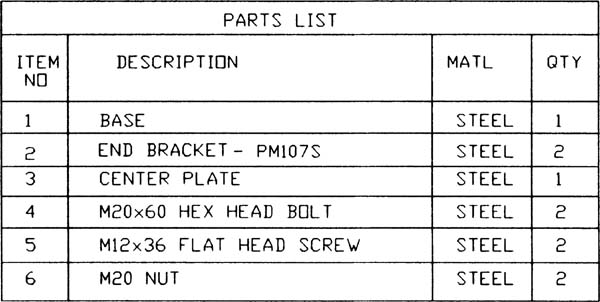
Figure 12-33
12-14 Drawing Problem
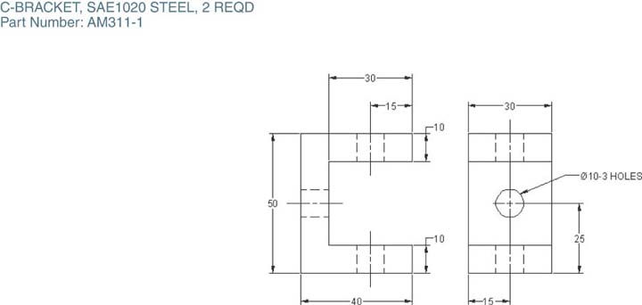
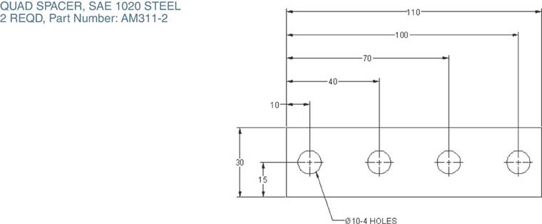
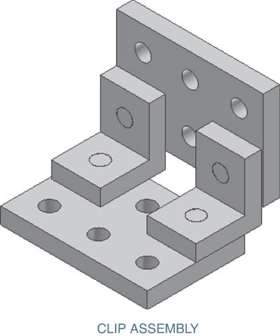
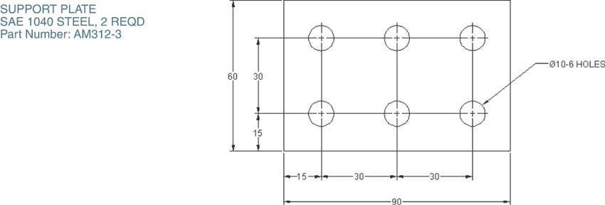
Figure 12-34 shows an assembly made from four different parts: a plate, a bracket, and two posts. The detail drawings of the parts are shown in Figure 12-35 on this and the following page.
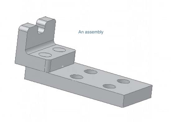
Figure 12-34


Figure 12-35
Creating an Assembly Drawing
Draw orthographic views of the parts in their assembled position (Figure 12-36).
In this example, only a front view and a top view were drawn, as these views are sufficient to define the assembly. The front view orientation was selected to display the profile of the assembled parts. Note that there are no hidden lines in assembly drawings.
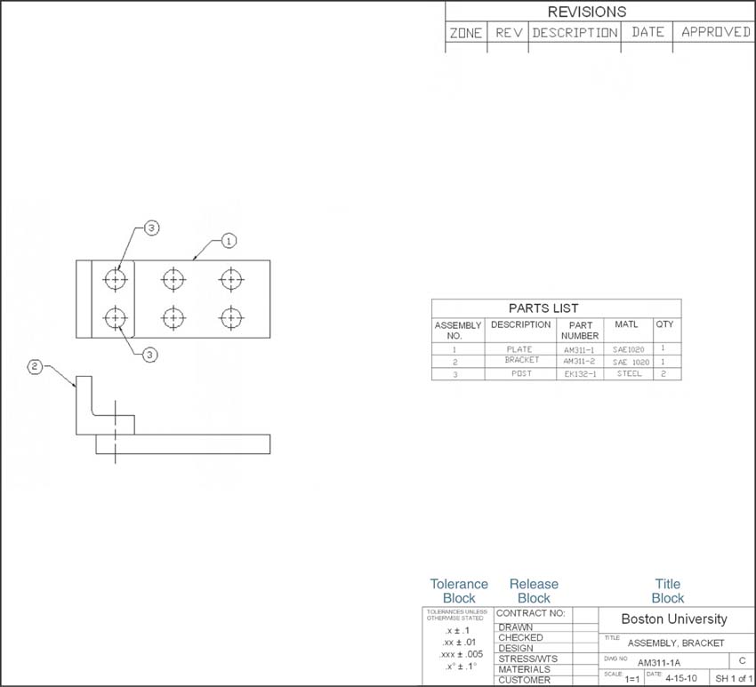
Figure 12-36
Add assembly numbers to the drawing.
Remember that assembly numbers are different from part numbers. A part number is a number assigned to an individual part and remains with that part regardless of what assembly uses the part. An assembly number is unique to each assembly and does not transfer to other assemblies.
Create a parts list for the assembly.
As stated earlier, there is no standard format for parts lists. The example shown represents an average approach. Note the use of assembly numbers and part numbers.
Add a title block, a release block, and a tolerance block.
12-15 Drawing Problem
Figure 12-37 shows another example of an assembly drawing. In this example, a front view, a right-side view, and a bottom view were used to define the assembly. The parts list is located on a second sheet. In general, drawings should not be overcrowded. Parts lists, sectional views, and other drawing information are often located on second or third sheets.
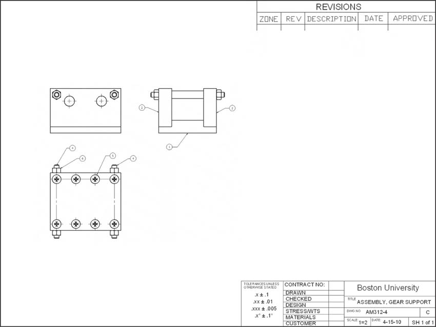
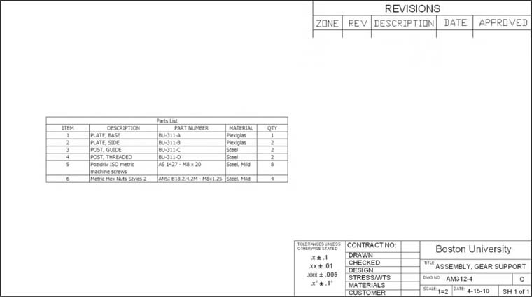
Figure 12-37
12-16 Exercise Problems
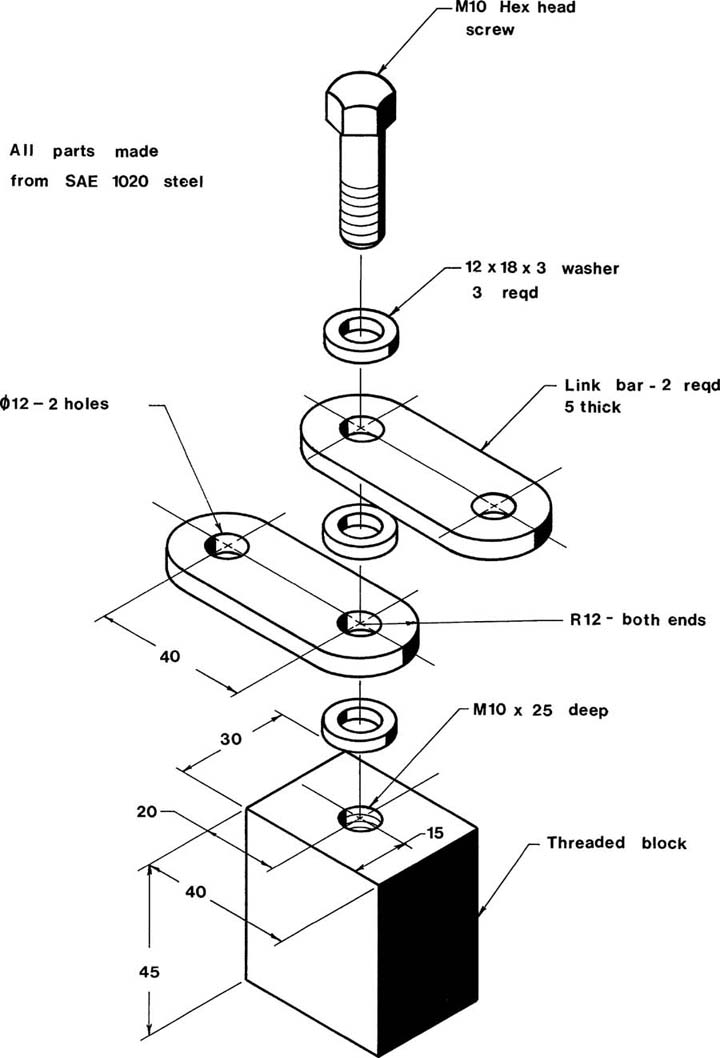
EX12-1 Millimeters
Draw an assembly drawing of the given objects.
Draw detail drawings for all nonstandard parts.
Prepare a parts list. Specify the length for the M10 hex head screw.
EX12-2 Millimeters
Draw an assembly drawing of the given objects.
Draw detail drawings for all nonstandard parts.
Prepare a parts list.

EX12-3 Millimeters
Draw an assembly drawing of the given objects.
Draw detail drawings for all nonstandard parts.
Prepare a parts list.

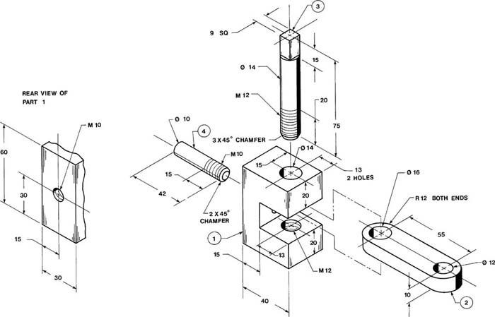
EX12-4 Millimeters
Draw an assembly drawing of the given objects.
Draw detail drawings for all nonstandard parts.
Prepare a parts list.
Replace part 3 with a bolt and an appropriate nut. Add four washers.
EX12-5 Millimeters
Draw an assembly drawing of the given objects.
Draw detail drawings for all nonstandard parts.
Prepare a parts list.

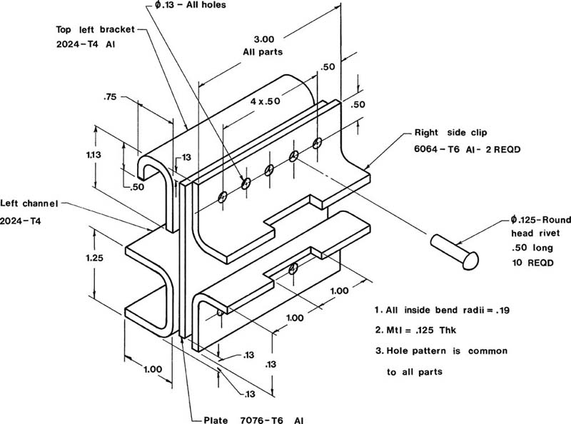
EX12-6 Millimeters
Draw an assembly drawing of the given objects.
Draw detail drawings for all nonstandard parts.
Prepare a parts list.
Replace the rivets with the appropriate screws and nuts.
EX12-7 Millimeters
Draw an assembly drawing of the given objects.
Prepare a parts list.

EX12-8 Inches
Draw an assembly drawing and parts list for the guide assembly.
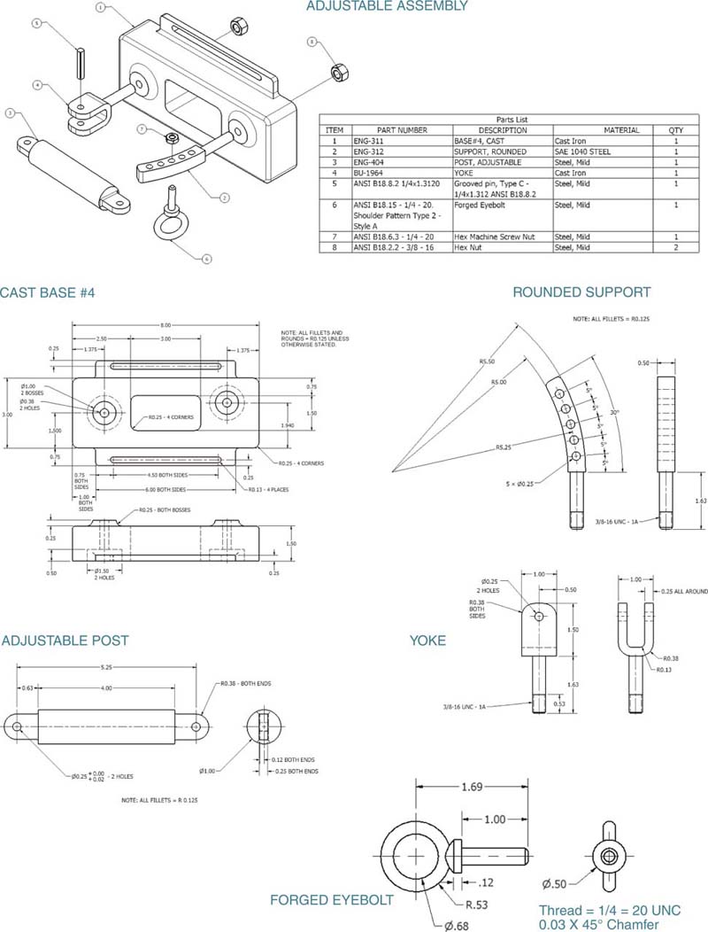
EX12-9
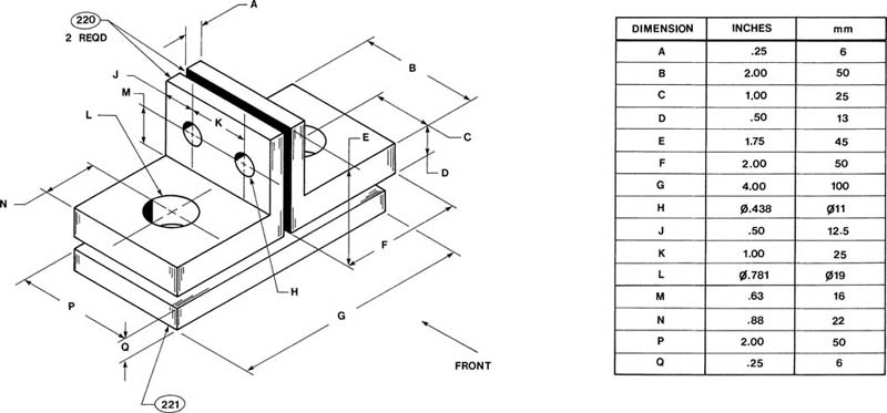
Redraw the given objects as an assembly drawing and add bolts with the appropriate nuts at the L and H holes. Add the appropriate drawing callouts. Specify standard bolt lengths.
Use inch values.
Draw the front assembly view, using a sectional view.
Draw the fasteners, using schematic representations.
Draw the fasteners, using simplified representations.
Prepare a parts list.
Prepare detail drawings for the parts.
Repeat steps 2 through 6 using millimeter values.
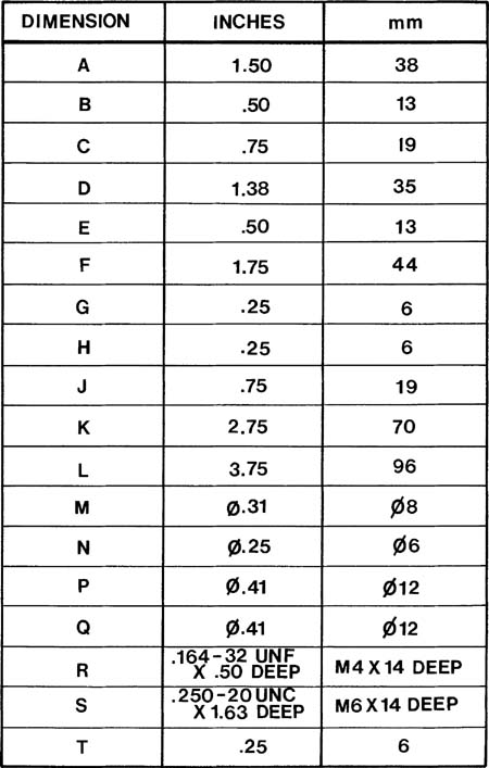
EX12-10
Redraw the given views and add the appropriate hex head machine screws at M and N. Use standard length screws and allow at least two unused threads at the bottom of each threaded hole. Add a bolt with the appropriate nut at hole P.
Use inch values.
Draw the front assembly view, using a sectional view.
Draw the fasteners, using schematic representations.
Draw the fasteners, using simplified representations.
Prepare a parts list.
Prepare detail drawings for the parts.
Repeat steps 2 through 6 using millimeter values.

EX12-11 Millimeters
Draw an assembly drawing and parts list for the circular damper assembly shown.

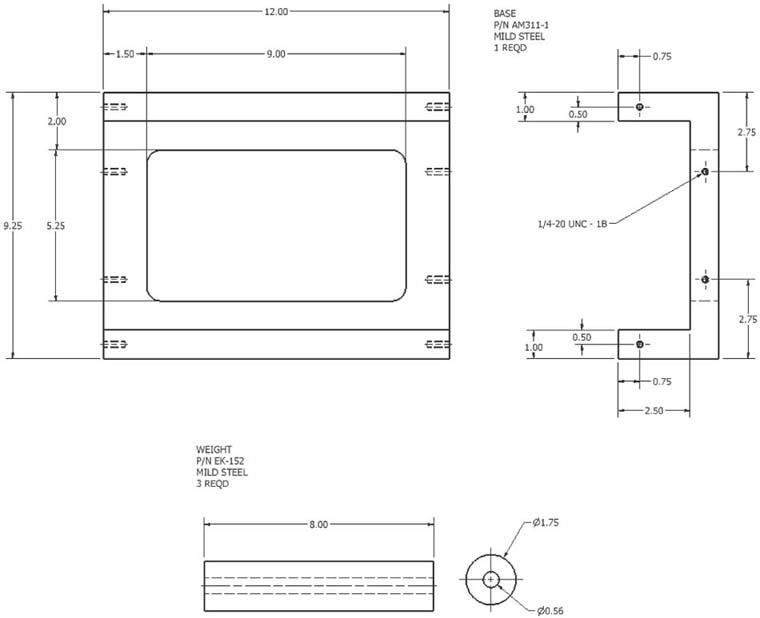
EX12-12 Inches
The objects shown on the pages that follow are to be assembled as indicated. Select sizes for the parts that make the assembly possible. (Choose dimensions for the end blocks and then determine the screw and stud lengths.) The hex head screws (5) have a major diameter of either 0.375 inch or M10. The studs (3) are to have the same thread sizes as the screws and are to be screwed into the top part (2). The holes in the lower part (1) that accept the studs are to be clearance holes.
Draw an assembly drawing.
Draw a detail drawing of each nonstandard part. Include positional tolerances for all holes.
Prepare a parts list.


EX12-13 Inches
Draw an assembly drawing and parts list for the winding assembly.


EX12-14 Inches
Design a hand-operated grinding wheel specifically for sharpening a chisel. The chisel is to be located on an adjustable rest while it is being sharpened. The mechanism should be able to be clamped to a table during operation via two thumbscrews.
A standard grinding wheel is ø6.00 inch and 1/2 inch thick and has an internal mounting hole with a 50 ± 0.03-millimeter bore.
Draw an assembly drawing.
Draw a detail drawing of each nonstandard part. Include positional tolerances for all holes.
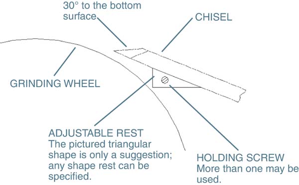
Prepare a parts list.
This is a nominal setup. It may be improved. Consider how the spacers rub against the stationary support and consider using double nuts at each end of the shaft.

EX12-15 Millimeters
Draw an assembly drawing of the given object.
Prepare a parts list.
Select appropriate fasteners to hold the object together.
Define the appropriate tolerances.
Define an assembly sequence, considering the size of any screw heads and nuts, and the tooling required for assembly.

EX12-16 Millimeters
Draw an assembly drawing of the given object.
Prepare a parts list.
Select appropriate fasteners to hold the object together.
Define the appropriate tolerances.
Define an assembly sequence, considering the size of any screw heads and nuts, and the tooling required for assembly.
EX12-17 Millimeters
Draw an assembly drawing of the given object.
Prepare a parts list.
Select appropriate fasteners to hold the object together.
Define the appropriate tolerances.
Define an assembly sequence, considering the size of any screw heads and nuts, and the tooling required for assembly.


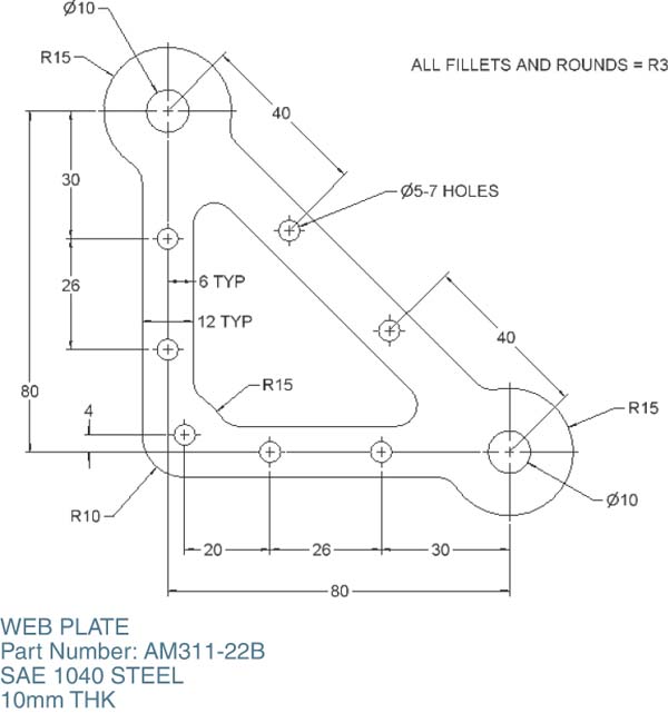
EX12-18 Millimeters
Draw an assembly drawing of the given object.
Prepare a parts list.
Select appropriate fasteners to hold the object together. Note that the fastener used to join the center link and the drive link passes over the web plate as the drive link rotates.
Define the appropriate tolerances.
Use phantom lines and define the motion of the center link and the rocker link if the drive link rotates 360°.
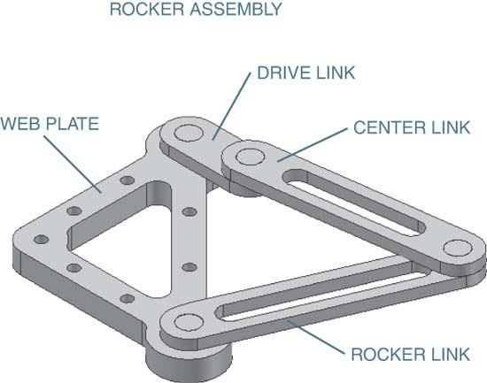


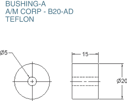
EX12-19 Millimeters
Draw an assembly drawing of the given object.
Prepare a parts list.
Select appropriate fasteners to hold the object together. Note that the fasteners used to join the side links to the holder arm pass over the holder base.
Define the appropriate tolerances. Use an H7/p6 tolerance between bushing-A and the holder base.
Use phantom lines to define the motion of the holder arm, side links, and cross link if the holder arm rotates between +30° and –30°.


EX12-20 Millimeters
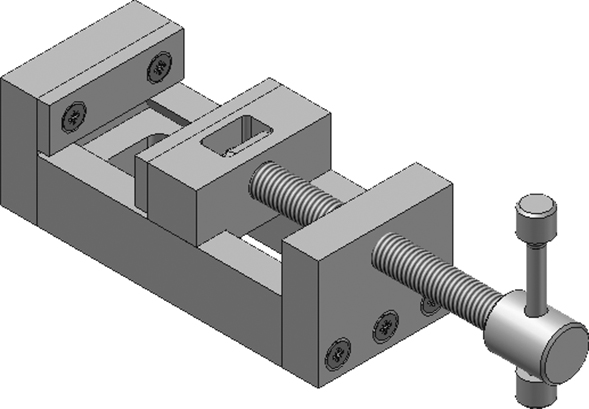
Draw an assembly drawing of the minivise.
Prepare a parts list.
Select the appropriate fasteners to hold the vise together.
Redesign the interface between the drive screw and the holder plate.
Minivise (Assembled View)
Minivise (Exploded View)
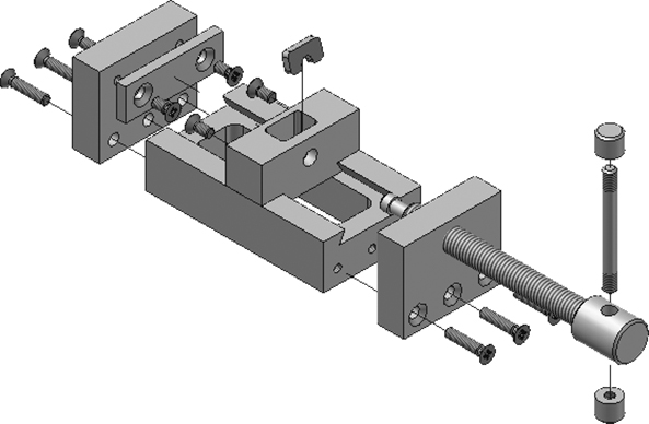
BASE
SAE 1040 STEEL

DRIVE SCREW
SAE 1040 STEEL

END PLATE
SAE 1040 STEEL

SLIDER
SAE 1040 STEEL

HOLDER PLATE
SAE 1040 STEEL

FACE PLATE
SAE 1040 STEEL

HANDLE
SAE 1040 STEEL
END CAP
SAE 1040 STEEL

DRIVE PLATE
SAE 1040 STEEL

M5 × 10 RECESSED COUNTERSUNK
HEAD STEEL
M5 × 22 RECESSED COUNTERSUNK
HEAD STEEL
EX12-21 Inches
Draw an assembly drawing of the rocker assembly.
Prepare a parts list that includes all parts used in the assembly.
Draw a detailed 2D drawing with dimensions of each manufactured part used in the assembly.
Do not create drawings of purchased parts, screws, nuts, washers, or bearings.


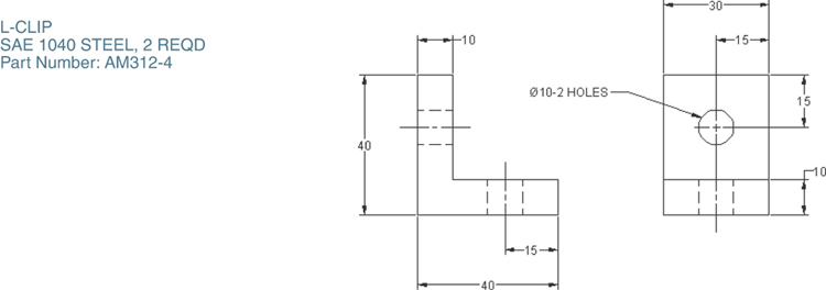
EX12-22 Millimeters
Draw an assembly drawing of the dome assembly.
Prepare a parts list that includes all parts used in the assembly.
Draw a detailed 2D drawing with dimensions of the semisphere.
Include section views as shown.

