IN THIS CHAPTER
Sampling and swapping fills and line styles
Applying the Gradient Transform tool to control gradient and bitmap fills
Using Modify Shape options
Working with the Free Transform tool and the Transform panel: Skewing and rotating
Working with 3D tools: Perspective, Translation, and Rotation
Stacking, grouping, and arranging item types
Combining drawing objects
Using Break apart and Trace bitmap
Creating and managing compound shapes
Autopilot editing with Find and Replace
After becoming familiar with the Flash authoring environment and learning to use the Drawing tools, you are now ready to move on to the fun part: messing with the basic shapes and text elements you have made to achieve custom results.
In this chapter, you revisit some of the core tools to show you new ways to apply them. I also introduce some specialized tools that exist only to transform your artwork. Following a look at how the Eyedropper, Paint Bucket, and Ink Bottle work together to modify strokes and fills, I show you how to use the Gradient Transform tool to create custom fills.
The Modify Shape submenu offers some special commands you can apply to alter lines and fills, whereas the Modify Transform submenu includes various options for skewing, stretching, rotating, flipping, and rotating shapes.
Before explaining the Flash stacking order and how to create compound shapes, I introduce the powerful Free Transform tool and the Envelope modifier that enables you to warp and distort multiple shapes simultaneously. Other features worth exploring include the stepped Break apart command on text and the indispensable Distribute to Layers command — these two features combined make animating text infinitely easier than it was in early versions of Flash.
Note
For coverage of advanced color effects and filters, refer to Chapter 11, "Applying Filters, Blends, Guides, and Masks."
Last but not least, I cover the Find and Replace command and the History panel. I introduce the options for these flexible features and demonstrate some ways you can use them to modify your graphics, without even using any tools!
As I introduce various techniques and tools, I show you how to apply them for modifying artwork and adding the illusion of depth and texture to your 2-D graphics.
You can always use the Selection tool to select a stroke or fill so that you can modify it by using any of the Swatches popups or the Stroke Style menu on the Properties panel. But, what do you do if you want to add a stroke or fill to a shape that was drawn without one or the other? The answer to this dilemma is found in a trio of tools that work nimbly together to provide one of the most unique graphics-editing solutions found in Flash. You use the Eyedropper tool to acquire fill and stroke styles or colors, and use the Paint Bucket and Ink Bottle tools to transfer these characteristics to other shapes.
Note
These tools only apply changes directly to shapes, shape primitives, or drawing objects, so to modify an element that has been grouped or converted into a symbol, you must first access the element in Edit mode.
As I introduced in Chapter 7, "Applying Color," the dropper icon that appears when you use the Selection tool to select colors from any of the popup Swatches menus is similar to the Eyedropper tool available in the Tools panel. However, when pulled out of the Tools panel directly, the Eyedropper tool (I) has slightly different behavior. Although you cannot use the Eyedropper tool to sample colors from elements outside the Document window, you can use it to sample line and fill styles or to simultaneously change the stroke and the fill color chips to the same sampled color.
Note
For more information about this feat, refer to Chapter 7, "Applying Color."
Note
When used to acquire colors, the Swatches panel Eyedropper tool is limited to picking colors from swatches within the panel. However, the droppers that you access from the Swatches popup menus in the Color panel or Tools panel can acquire colors from other visible areas, such as the system background, items on the desktop, or items open in other applications. The functionality of this feature is not totally consistent, so here are some tips to making it work:
When picking colors by using the dropper from the Color panel swatches popup, press and hold the mouse as you roll over color chips in the popup or colors anywhere on your desktop and release the mouse only when you are hovering over the color that you want to sample. The preview in the swatches popup changes as you roll over different colors, and the color chip changes when you release the mouse to load the color that you have selected.
If you are using the dropper from the Tools panel color chip swatches popup, the behavior is a bit different: Click once on the color chip to open the swatches popup, and then move the dropper to roll over any color in the popup or on your desktop and click again to pick the color and load it into the current color chip. The droppers available from the swatches popups for any of the color chips in the Properties panel work the same way as the droppers in the Tools panel swatches popup, but they are limited to picking colors from within the Flash application (or the currently loaded swatches).
The Eyedropper tool doesn't have any options in the Tools panel because they are all built in. As you hover over an item, the Eyedropper tool displays a small icon to indicate whether it is over a line or a fill that can be sampled by clicking. When a line is sampled, the Eyedropper tool automatically converts to the Ink Bottle tool, and when a fill is sampled, the Eyedropper tool converts to the Paint Bucket tool.
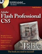
The composite image shown in Figure 9.1 shows the icons that appear when you use the Eyedropper tool to sample a fill (A) and apply it to another shape with the Paint Bucket tool (B), and sample a stroke (C) and apply it to another shape with the Ink Bottle tool (D).

Figure 9.1. The Eyedropper tool used to sample a fill and apply it with the Paint Bucket tool (A, B) and to sample a stroke and apply it with the Ink Bottle tool (C, D)
Any items already selected when the Eyedropper tool samples a stroke or fill immediately acquire the applicable stroke or fill style. This is the quickest way to transfer the fill or line styles of one element to a whole group of elements. Figure 9.2 shows the Eyedropper tool used to sample a fill with one (A) or more (B) elements already selected.

Figure 9.2. The Eyedropper tool also instantly converts selected elements to the sampled fill or stroke style.
Tip
When you press and hold the Shift key while clicking a line or stroke color with the Eyedropper tool, the Fill and the Stroke color chips both convert simultaneously to the newly selected color so that it can be applied with any of the other drawing tools.
You use the Ink Bottle tool (S) — refer to Figure 9.1 (D) — to change the color, style, and thickness of existing outlines. It is most often used in conjunction with the Eyedropper tool. When the Ink Bottle tool is in use, pay attention to the following three options:
The current Stroke Color option on the Tools panel or the Properties panel
The Stroke weight (or thickness) setting in the Properties panel
The Stroke Style setting in the Properties panel
The Ink Bottle applies the current stroke color and line style, either sampled with the Eyedropper tool or chosen from the popup in the Tools panel or the controls in the Properties panel.
Warning
When you click to sample a line with the Ink Bottle tool, all other currently selected lines are changed simultaneously.
The Ink Bottle tool is especially useful for applying custom line styles to multiple lines. You can build a collection of custom line styles either off Stage or in a special custom line palette saved as a single-frame Flash movie. You can then acquire these line styles whenever you want to reuse them.
Tip
You can add Flash files with graphics libraries that you plan to reuse to the application's Libraries folder so that they can be easily accessed from the Window
Note
Depending on the level of zoom, some lines may not appear accurately on the screen — though they print correctly on a high-resolution printer. You may adjust Stroke weight in the Fill and Stroke section of the Properties panel.
You use the Paint Bucket tool to fill enclosed areas with color, gradients, or bitmap fills. Although the Paint Bucket tool is a more robust tool than the Ink Bottle tool, and it can be used independently, it's most often used in conjunction with the Eyedropper tool. As discussed earlier in this chapter, when the Eyedropper tool picks up a fill, it first acquires the attributes of that fill and then automatically changes itself to the Paint Bucket tool. When the Paint Bucket tool is active, shown in Figure 9.3, two options are available from the Tools panel: Lock Fill and Gap size. The Gap size drop-down menu offers four settings to control how Flash handles gaps or open spaces in lines when filling with the Paint Bucket tool.

When you use the Eyedropper tool to acquire a bitmap fill, the Eyedropper tool is automatically swapped for the Paint Bucket tool and a thumbnail of the bitmap image appears in place of the fill color chip. This procedure also automatically engages the Paint Bucket Lock Fill option.
Note
The scale of the bitmap fill is consistent, no matter how it is selected and applied. As described later in this chapter, you can use the Gradient Transform tool to modify the scale of a bitmap fill as needed.
Warning
Using the Paint Bucket to fill with white (or the background color) is not the same as erasing. Painting with white (or the background color) may appear to accomplish something similar to erasing. However, you are, in fact, creating a filled item that can be selected, moved, deleted, or reshaped. Only erasing erases!
Another helpful behavior of the Paint Bucket tool is that the exact location where you click to apply the Paint Bucket tool defines the highlight point for the fill. This has no visible effect when filling with solid colors or bitmap fills, but when filling with gradients it affects how the fill is rendered within the boundaries of the shape. Figure 9.4 illustrates how the highlight of a gradient fill varies based on where it was "dumped" with the Paint Bucket.
Tip
You can also adjust the highlight and the center point of the rendered gradient with the Gradient Transform tool after a shape is filled.

Figure 9.4. The highlight location of gradient fills can be defined by the position of the Paint Bucket tool when the fill is applied to a shape.
As with the Ink Bottle tool, the Paint Bucket tool can be especially useful for applying custom fill styles to multiple items. You can build a collection of custom fill styles either off-screen (on the Pasteboard) or in a special, saved, custom-fills-palette, single-frame Flash movie. You can then acquire these fills whenever necessary.
Warning
If you click with the Paint Bucket tool on one of several selected fills, all the selected fills simultaneously change to the new fill.
As shown in Figure 9.3, the Gap size option drop-down offers four settings that control how the Paint Bucket treats gaps when filling. These settings are Don't Close Gaps, Close Small Gaps, Close Medium Gaps, and Close Large Gaps. These tolerance settings enable Flash to fill an outline if the endpoints of the outline aren't completely joined, leaving an open shape. If the gaps are too large, you may have to close them manually with another drawing tool. Figure 9.5 illustrates how the Gap size option settings affect the Paint Bucket fill behavior.
Tip
The level of zoom changes the apparent size of gaps. Although the actual size of gaps is unaffected by zoom, the Paint Bucket's interpretation of the gap is dependent upon the current Zoom setting. When zoomed in very close, the Paint Bucket tool finds it harder to close gaps; when zoomed out, the Paint Bucket tool finds it easier to close gaps.

Figure 9.5. Paint Bucket fill applied with various Gap size settings: (A) original oval outline with decreasing gap sizes, left to right, with no fill; (B) gray fill applied with Don't Close Gaps; (C) gray fill applied with Close Small Gaps; (D) gray fill applied with Close Medium Gaps; (E) gray fill applied with Close Large Gaps
The Paint Bucket's Lock Fill option is the same as the Brush Lock Fill option — it controls how Flash handles areas filled with gradient color or bitmaps. When this button is turned on, all areas (or shapes) painted with the same gradient or bitmap appear to be part of a single, continuous, filled shape. The Lock Fill option locks the angle, size, and point of origin of the current fill to remain constant throughout any number of selected shapes. Modifications made to the fill in one of the shapes are applied to the other shapes filled by using the same Lock Fill option.
Note
Working with gradient colors is discussed in Chapter 7, "Applying Color."
To demonstrate the distinction between fills applied with or without the Lock Fill option, I created five shapes and filled them with a bitmap with Lock Fill off. As shown in Figure 9.6, on the left, the image was rendered individually from one shape to the next. On the right, those same shapes were filled with the same bitmap, but with Lock Fill on. Note how the image is now continuous from one shape to the next. Bitmap fills are automatically tiled to fill a shape, so the bitmap fill on the right was also scaled with the Gradient Transform tool to make it easier to see the continuation of the image between the various shapes.

Figure 9.6. Fill applied with Lock Fill turned off (left), compared with fill applied with Lock Fill turned on and then scaled by using the Gradient Transform tool (right)
Note
When you use the Eyedropper tool to pick up a fill or gradient from the scene, the Lock Fill button is automatically toggled on.
Warning
If the shapes you are filling with the Paint Bucket tool were created with the Object Drawing option turned on or drawn with one of the Shape Primitive tools, you can use the Lock Fill option to get a fill that continues from one shape to the next, but when you try to adjust the fill with the Gradient Transform tool, you will find that the fills are transformed individually instead of as a group. The workaround for this glitch is to use raw shapes when you apply a locked fill that you plan to transform. If you started with drawing objects or shape primitives, use the Break Apart command before you try to use the Gradient Transform tool to adjust a continuous fill on multiple shapes.
You can find the Gradient Transform tool (F) in a drop-down within the same tile on the toolbar as the Free Transform tool (Q). Gradient Transform is used only to modify bitmap or gradient fills and does not apply to simple color fills. The Gradient Transform tool does many of the same things the Free Transform tool does, but it modifies only the fill of a shape without changing the stroke or outline appearance at all. This type of adjustment is a lot like shifting, rotating, or scaling a larger piece of material behind a frame so that a different portion is visible.
The Gradient Transform tool has only one option in the Tools panel, but, as with the Eyedropper tool, it does apply differently depending on the type of fill selected. To use the Gradient Transform tool, select it in the Tools panel, and then simply click an existing gradient or bitmap fill. A set of three or four adjustment handles appears, depending on the type of fill. The following three transformations can be performed on a gradient or bitmap fill: adjusting the fill's center point, rotating the fill, and scaling the fill. The extra set of adjustment handles appearing on bitmap fills enables them to be skewed. The Magnet option in the Tools panel toggles on Snapping behavior, making it easier to constrain transformations to even adjustment increments. Figure 9.7 illustrates the various adjustment handles on three types of fills.

Figure 9.7. The Gradient Transform tool applied to a radial gradient (A), a linear gradient (B), a tiled bitmap fill (C), and a scaled bitmap fill (D). Each handle type has an icon to indicate its function.
The position of these handles may shift if a fill (or bitmap fill) has been variously copied, rotated, or pasted in any number of ways. The fundamental rules are as follows:
The round center handle moves the center point.
The extra center pointer on radial gradients moves the highlight.
The round corner handle with the short arrow rotates.
The square edge handles scale either vertically or horizontally.
The round corner handle with a long arrow scales symmetrically.
The diamond-shaped edge handles on bitmap fills skew either vertically or horizontally.
Tip
To see all the handles when transforming a large element or working with an item close to the edge of the Stage, choose View
If the fill is not aligned in the shape as you would like it to be, you can easily move the center point to adjust how the shape outline frames the fill. To adjust the center point, follow these steps:
Deselect the fill if it has been previously selected.
Choose the Gradient Transform tool from the Tools panel.
Click the fill.
Bring the cursor to the small circular handle at the center of the fill until it changes to a four-arrow cursor, pointing left, right, up, and down, like a compass, indicating that this handle can now be used to move the center point in any direction.
Drag the center circular handle in any direction you want to move the center of the fill.
Figure 9.8 shows a radial gradient (left) repositioned with the Gradient Transform tool (right).

The Gradient Transform option enables you to adjust the highlight of a radial gradient without moving the center point of the fill. As shown in Figure 9.9, you can drag the extra pointer above the center point circle to move the highlight of the gradient along the horizontal axis. If you want to move the highlight along a vertical axis, use the rotate handle to change the orientation of the fill.

Figure 9.9. The Gradient Transform handle enables you to adjust the highlight of a radial gradient without moving the center point of the fill.
Tip
The Paint Bucket tool is also a handy way to set the highlight point of a gradient fill. Select the gradient that you want to apply, and then click inside the shape where you want the highlight to be. You can keep clicking in different areas of the shape with the Paint Bucket to move the highlight around until you like it.
To rotate a gradient or bitmap fill, find the small circular handle that's at the corner of the fill. (In a radial gradient, choose the lower circular handle.) This circular handle is used for rotating a fill around the center point. Simply click the circular handle with the Rotate cursor and drag clockwise or counterclockwise to rotate the fill. Figure 9.10 shows a bitmap fill (left) as it appears when rotated clockwise (right).
Tip
Activate the Snap to Objects toggle in the Tools panel if you want to use snapping behaviors to help guide rotating or scaling of a fill. (Turn behaviors on or off in the application menu under View

To resize a bitmap fill symmetrically (to maintain the aspect ratio), find the round corner handle with an arrow icon, which is usually located at the lower-left corner of the fill. On rollover, the diagonal arrow icon appears, indicating the direction(s) in which the handle resizes the fill. Click and drag to scale the fill symmetrically. On radial gradients, you use the round-corner handle with the longer arrow icon to scale with the gradient aspect ratio constrained. Linear gradients have only one handle for scaling, and this handle always scales in the direction of the gradient banding.
To resize a fill asymmetrically, find a small square handle on either a vertical or a horizontal edge, depending on whether you want to affect the width or height of the fill. On rollover, arrows appear perpendicular to the edge of the shape, indicating the direction in which this handle resizes the fill. Click and drag a handle to reshape the fill.
Figure 9.11 shows the three fill types with their respective scale options. Linear gradient fills (left) can be scaled only in the direction of the gradient banding, but they can be rotated to scale vertically (lower) rather than horizontally (upper). Radial gradient fills (center) can be expanded symmetrically (upper) with the circular handle, or asymmetrically (lower) with the square handle. As with linear gradients, they can be rotated to scale vertically rather than horizontally. Bitmap fills (right) can be scaled by the corner handle to maintain the aspect ratio (upper), or dragged from any side handle to scale asymmetrically (lower).
Warning
Adjusting bitmap fills with the Gradient Transform tool can be tricky business. On tiled fills, the transform handles are often so small and bunched together that they are difficult to see. On full-size bitmaps, the handles are sometimes outside the Stage, and it can be hard to find the handle that you need. It can also be unpredictable where the handles appear when you select a bitmap fill with the Gradient Transform tool — often they are outside the shape where the fill is visible. Our advice is to use this workflow only when you have no other choice. In general, it is a much better idea to decide on the size for a bitmap and create a Web-ready image that you can use without scaling before you import it to Flash.
Note
The right column of Figure 9.11 is a good example of how changes applied to one tile in a bitmap fill are passed to all the other tiles within the shape.
As you work with scaled gradient fills, you will quickly notice that your shape is always filled from edge to edge but that the fill area may not appear quite how you'd like it to. In early versions of Flash, you were stuck with the solid color fill around the edges when a gradient was scaled smaller inside of a shape. This default behavior is now part of the Overflow menu in the Color panel that gives you some other options for how a gradient renders when it is scaled down. As shown in Figure 9.12, there are three different overflow styles:
Extend: Extends the colors on the outside edge of the gradient to create a solid fill beyond the edge of the rendered gradient
Reflect: Alternates flipped (reflected) versions of the original gradient until the shape is filled from edge to edge
Repeat: Renders the color pattern of the original gradient repeatedly until the shape is filled from edge to edge


To skew a bitmap fill horizontally, click the diamond-shaped handle at the top of the image; arrows appear, parallel to the edge of the fill, indicating the directions in which this handle skews the fill. Drag to skew the image in either direction. Figure 9.13 shows a bitmap skewed horizontally (left) and vertically (right). Note that the skew procedure is still active after it has been applied, meaning that the skew may be further modified — this behavior is common to all functions of the Gradient Transform tool.

Note
Gradient fills cannot be skewed; they can be scaled only on the horizontal or vertical axis.
Tip
If you get carried away with the Gradient Transform tool and you want to get back to the original fill position and size, double-click the center icon of the shape to reset all transformations.
You apply the Gradient Transform tool most often to get a patterned fill or a gradient aligned and sized within its outline shape. A simple way of adding more depth to shapes is to modify gradient fills so that they appear to reflect light from one consistent source. You can choose to emulate a soft light for a more even illumination, or to emulate a hard, focused light that emphasizes dramatic shadows. As you create a composition on the Stage, you can use the Gradient Transform tool to modify individual elements so that they appear to share a common light source. Figure 9.14 illustrates how a default radial gradient (left) can be modified to emulate a soft (center) or hard (right) illumination.

To show how these lighting effects can be applied to create the illusion of 3-D, I created a little scene by using only radial fills that were modified with the Gradient Transform tool. Figure 9.15 shows the radial gradients as they appeared when I drew them with the default settings (left) and how the scene appeared after I modified the gradients with Gradient Transform and some basic shape scaling as I describe later in this chapter.
Note
If you want to deconstruct this example, I have included the file on the CD-ROM with both the unmodified and the final transformed shapes. You will find the file named SphereLighting.fla in the ch09 folder of the CD-ROM.

Three specialized commands found in the application menu (under Modify
Note
I discuss the Selection tool, Subselection tool, and the Smooth, Straighten, and Optimize commands (also found in the Modify Shape menu), in Chapter 5, "Drawing in Flash."
Lines to Fills does exactly what its name implies: It converts lines defined by single points into shapes defined by an outline of editable points. To apply the Lines to Fills command, simply select any lines that you want to convert before choosing Modify
Tip
You can render strokes and lines by using gradients without converting them into fills.
The Lines to Fills command is especially important because it provides the one solution for maintaining line-to-fill ratios when scaling raw graphics that would require lines to appear at smaller than 1 point size. Fills do not have the same display limitation as lines, and they maintain visual consistency as they are scaled larger or smaller. In Figure 9.16, the image on the left was drawn with the Pencil tool to make lines around the eyes and on the whiskers of the cat cartoon. When it was scaled, the lines were not visually consistent with the fills. The image on the right was modified by using the Lines to Fills command before scaling it down to 25 percent size. In this case, the ratio between the outlines around the eyes and the whiskers was consistent with the other filled shapes in the cartoon.
Tip
If you convert your raw graphic into a symbol before you scale it, the ratio of lines to fills also stays consistent.
Note
The stroke scale settings in the Properties panel are discussed in Chapter 5, "Drawing in Flash." These settings are helpful for maintaining a specific stroke weight on graphics that will be scaled horizontally or vertically, but they do not solve the display issue discussed here (and shown in Figure 9.16), when scaled lines need to appear at less than 1 point.

Note
Remember that in Flash, the smallest line size that can be displayed is 1 point. Lines with a height of less than 1 point all appear to be the same size on-screen when viewed at 100 percent scale. The difference in size is visible only when the view is scaled larger (zoomed in). However, the lines print correctly on a high-resolution printer and are visible in the published .swf if the content is zoomed.
The Expand Fill command has two options you can use to size fills up or down evenly on all sides of a shape. To apply the command, select the fill(s) that you want to modify, and then choose Modify
Warning
You cannot apply the Expand Fill command to drawing objects with strokes unless you first break them apart or open them in Edit mode so that you can select the fill without also selecting the stroke.
Figure 9.17 includes a rectangle, a cartoon cat, and a sketch of some grapes. The original shapes are shown on the left, the expanded fills in the center, and the inset fills on the right. As you can see, expanding fills often obscures the strokes surrounding a shape, whereas choosing to inset a fill leaves space between the fill and any surrounding stroke.

Figure 9.17. Modifying an original shape (A) with the Expand Fill command, using the Expand option (B) or the Inset option (C), respectively, bloats or shrinks a fill by a specified pixel amount.
Note
Each of the fills in the graphics shown in Figure 9.17 was added by clicking or Shift+clicking (rather than dragging out a selection marquee) to avoid including any strokes in the final selection that were modified with the Expand Fill command.
You can also use the Expand Fill command to create custom text forms. Figure 9.18 shows how the original text shape (left) can be modified by using either the Expand or Inset option. To create bloated balloon-like text (center), or shrunken, eroded text (right), you first have to apply the Modify

The Soften Fill Edges command was the closest thing to a static blur available before Flash 8. Fortunately, Flash 8 and newer versions support a much more sophisticated Blur filter that renders smoother softened edges and enables you to change the color of the item even after the blur is applied. The only advantages that the Soften Fill Edges command has over the Blur filter are that you can use it to modify raw shapes or drawing objects and choose whether to render it inside or outside the item's original fill boundary. This command, as with the Expand Fill command, can be applied only to fills and gives you the option to expand or inset the shape by a specific number of pixels.
Warning
Flash enables you to select a line and choose the Soften Edges command from the Modify
The blurry effect of Soften Fill Edges is created by a series of banded fills around the original fill that decrease in opacity toward the outermost band. You can control the number and width of these bands by entering values in the Soften Fill Edges dialog box (shown in Figure 9.19) to create a variety of effects, from a very subtle blurred effect to a dramatic stepped appearance around the edges of the fill.

The Soften Fill Edges dialog box controls the following features of the fill modification:
Distance: Defines the number of pixels the original shape expands or shrinks
Number of steps: Sets the number of bands that appear around the outside edge of the fill
Expand or Inset: Controls whether the bands are added to the outside edge of the fill (expand) or stacked on the inside edge of the shape (inset)
Figure 9.20 shows how the original fill (left) appears after Soften Fill Edges is applied with the Expand option (center), or with the Inset option (right).

The width of the individual bands equals the total number of pixels set in Distance divided by the Number of steps. When the edge of the shape is magnified, the individual bands can clearly be seen. Figure 9.21 compares a series of eight bands, each 1 pixel wide, created by using a Distance setting of 8 and a Number of steps setting of 8, compared with the smooth softened edge that results from applying a Blur filter with an X and Y setting of 8.

Figure 9.21. A magnified view of the banded edge of a fill created by applying Soften Fill Edges (left) compared to the smooth softened edge created by applying the Flash Blur filter (right)
As with the Expand Fill command, Soften Fill Edges can create interesting text effects when applied to broken-apart letter shapes. Figure 9.22 shows an effect created by combining the original white text with a "shadow" made by applying the Soften Fill Edges command to a broken-apart copy of the text that was filled with dark gray.
Tip
You can achieve an effect similar to the shadow shown in Figure 9.22 by applying the Glow filter to an editable text field and selecting the knockout option. I cover the various Flash filters in Chapter 12, "Applying Filters, Blends, Guides, and Masks."
The commands you have seen so far in this chapter are generally used for localized modification of lines or fills. In this section, I introduce some commands that are applied to create more dramatic change of whole items or even groups of items.
You can apply the basic transform commands to any element in the Flash authoring environment, but it is important to know that any transformations applied to symbols, groups, drawing objects, or text blocks are saved in the Info panel even if they are deselected and then reselected later. This enables you to easily revert these items to their original appearance. The transform settings for primitive shapes, on the other hand, are reset to the default values in the Info panel as soon as they are deselected. This means that while a primitive shape is actively being modified, you can revert to the original appearance, but as soon as you apply a change and deselect the shape, its modified appearance will be considered original the next time you select it. As shown in Figure 9.23, there are various ways to access the transform commands available in Flash.

Figure 9.23. The various ways to access transform commands in Flash — the Transform panel (lower left), the Modify Transform submenu (center), and the Free Transform tool (right)
The Transform panel (Ctrl+T/
The Copy and Apply Transform button is used to duplicate the selected item with all transformations included. When you select this button, you may not notice that anything has happened to your selected item — this is because Flash places the duplicate exactly on top of the original. To see both the original and the duplicate, drag the duplicate to a new position in the Document window.
The Reset button reverts a transformed symbol, group, or text field to its original appearance and returns all values in the Transform panel to the default settings. You can also achieve this by choosing Modify

The commands found in the application menu under Modify
Rotate 90 degrees CW or Rotate 90 degrees CCW: Used to rotate any selected items by a half-turn in the chosen direction (clockwise or counterclockwise) around the central axis point of the selection.
Tip
You can also use shortcut keys to rotate any selected item in 90-degree increments. To rotate an item 90 degrees clockwise, use Shift+Ctrl+9/Shift+

Flip Vertical or Flip Horizontal: Used to place the item in a mirrored position either on the vertical axis (calendar flip) or the horizontal axis (book flip).
The Free Transform tool (Q), available directly from the Tools panel, enables you to apply transform commands dynamically with various arrow icons. These icons appear as you position the pointer over the control points or handles of the selected item. You can also invoke various transform states from the contextual menu. Although the position of these arrow icons can vary with the position of the pointer, they provide a consistent indication of what transformation will be applied from the closest available handle. To finish any transformation, simply deselect the item by clicking outside of the current selection area.
Move arrow: This familiar arrow indicates that all currently selected items can be dragged together to a new location in the Document window.
Axis point or transformation point: By default, this circle marks the center of shapes as the axis for most transformations or animation. By dragging the point to a different location, you can define a new axis or transformation point for modifications applied to the item. To return the axis point to its default location, double-click the axis point icon.
Skew arrow: This arrow is generally available on any side of an item between transformation points. By clicking and dragging the outline, you can skew the shape in either direction indicated by the arrows.
Rotate arrow: This arrow is generally available near any corner of an item. By clicking and dragging, you can rotate the item clockwise or counterclockwise around the transform axis. Note that if you position the arrow directly over the closest corner handle, the Rotate arrow is usually replaced with the Scale Corner arrow. To rotate around the opposite corner point without moving the axis point, press the Alt (Option) key while dragging. To constrain rotation to 45-degree increments, press Shift while dragging.
Scale Side arrow: This arrow is available from any handle on the side of an item. Clicking and dragging scales the item larger or smaller, in one direction only, relative to the transform axis.
Scale Corner arrow: This arrow appears only on the corner handles of an item and is used to evenly scale the item larger or smaller, in all directions from the transform axis. To constrain the aspect ratio of the shape, press Shift while dragging.
Figure 9.24 shows how a symbol (or drawing object) and a shape appear differently after they have been modified, deselected, and then reselected with the Free Transform tool. The symbol (left) displays transform handles that are aligned with the originally modified item, and the values of the transformation settings are preserved in the Transform panel. The shape (right), however, displays transform handles aligned to default values unrelated to the original modifications, and the values in the Transform panel are reset to their defaults.

Figure 9.24. The Free Transform handles and Transform panel settings that appear for a symbol or drawing object (left) and for a simple shape (right) that have been reselected after an initial modification
The first two options in the Tools panel for the Free Transform tool (shown in Figure 9.23) are toggles to limit the modifications that can be applied to a selected item. It can sometimes be easier to use the Free Transform tool with more specific behavior. When the Rotate and Skew button or the Scale button is toggled on, all other modifications are excluded.
The Rotate and Skew toggle protects the selected item from being scaled accidentally while you're rotating or skewing it. This Tools panel option is equivalent to choosing Modify
The Scale toggle protects the selected item from all other transformations while it is being sized larger or smaller. This Tools panel option is equivalent to choosing Modify
The last two options in the Tools panel for the Free Transform tool — Distort and Envelope — are not available for symbols, groups, or text fields. However, when you're transforming drawing objects or primitive shapes, you can use these two options to create complex modifications not easily achieved with other Flash tools.
Note
Remember that you can access the raw shapes in a group or symbol by entering Edit mode. You can also convert text fields into shapes by applying the Break Apart command (twice).
Distort works by widening or narrowing the sides of the item, or stretching out the corners. This transform option does not bend or warp the shape; it allows sides of the shape to be scaled individually. To apply Distort, first select a shape with the Free Transform tool in the Tools panel, and turn on the Distort toggle in the Options area of the Tools panel. You can then click and drag handles on the sides or corners of the item to stretch or compress individual sides. This is equivalent to selecting a shape with the Selection tool and choosing Modify
Tip
You can also apply the Distort option to a shape that has been selected with the Free Transform tool by pressing Control (
Figure 9.25 shows an original shape being modified with the Distort option (left), and the final shape with distort handles, as they appear when the shape is reselected (right).
The Envelope option enables you to work with control points and handles much the same way you would when editing lines or shapes with the Subselection tool. The powerful difference is that the Envelope can wrap around the outside of multiple items so that the control points and handles curve, scale, stretch, or warp all the lines and shapes contained within the Envelope selection.

To apply the Envelope, first select a shape or multiple shapes with the Free Transform tool and then toggle on the Envelope option in the Tools panel. The Envelope offers a series of control points and tangent handles. The square points are used to scale and skew the shape(s), whereas the round points are actually handles used to control the curve and warp of the shape(s). You can also access the Envelope option by selecting the shapes you want to transform and choosing Modify
Figure 9.26 shows an original shape being modified with the Envelope option (left), and the final shape with Envelope handles, as they appear when the shape is reselected (right).

You can create faux-3D effects by skewing and scaling graphics with the Free Transform tool (as described in the previous section); however, this task has been made a whole lot easier by the new 3D tools available in Flash CS5. Instead of using your math and geometry skills to approximate perspective, you can simply click and drag intuitive handles and Flash applies distortion to your graphics to give them the appearance of existing in 3D space.
The 3D Rotation tool and the 3D Translation tool are both found in the Tools panel just below the Free Transform tool. Settings for these tools can be accessed in the Transform panel when the 3D tools are active or a 3D symbol is selected in your Document window. If you haven't worked with 3D tools before, the various options can be a little disorienting at first, but with a little trial and error you will soon get your bearings.
Note
To use the 3D tools in Flash, the Publish settings of your FLA file must be set to Flash Player 10 and ActionScript 3.0. All elements must be converted into Movie Clip instances to apply 3D Rotation or Translation.
To help you get started, I have included definitions for some of the terms you will come across when working with Flash symbols in 3D space:
x-axis: Sets the position of the symbol in relation to the Stage, tracked from left to right. Rotating (transforming) a symbol around the x-axis is like flipping a Rolodex. Moving (translating) an object along the x-axis makes it appear closer to the left or right side of the Stage.
y-axis: Sets the position of the symbol in relation to the Stage, tracked from top to bottom. Rotating a symbol around the y-axis is like turning a revolving door. Moving an object along the y-axis makes it appear closer to the top or bottom of the Stage.
z-axis: Sets the position of the symbol in relation to the depth of the space. This is the third axis that was added to Flash CS5 to support transformation and rotation of symbols for (faux) 3D. Rotating an object around the z-axis is like spinning a bicycle tire or moving the hands of a clock, although the center point can be adjusted so it is not always in the middle of the symbol. Moving an object along the z-axis makes it appear larger (closer) or smaller (farther away).
3D Translation: Changing the location of a symbol in 3D space is called a translation. The 3D Translation tool provides handles for moving a symbol along the x, y, and z-axis individually.
3D Transformation: Rotating an object in 3D space is called a transformation. The 3D Rotation tool provides handles for rotating a symbol along the x, y, and z-axis individually or along the x and y-axis at the same time — for "free rotation."
3D Center point: By default, the 3D center point is usually the center point of the symbol, but by moving the 3D center point you can change the way 3D transformations (rotations) affect the symbol, in the same way that changing the center point for scaling or rotating an object in 2D space modifies the outcome of any changes.
Global 3D space: This is the default setting for the 3D tools and means that any changes to location or rotation of a symbol are made in relation to the main Stage drawing area.
Local 3D space: This is an alternative setting for the 3D tools (a toggle button at the bottom of the Tools panel appears when 3D tools are active), and it restricts changes to location or rotation of nested symbols to the drawing space of the container symbol.
Note
3D rotations and translations can be animated to create cool effects, but I defer discussion of tweened 3D to Chapter 10, "Timeline Animation and the Motion Editor."
There is only one camera view in the authoring environment for your Flash movie. The camera view consists of a perspective angle and a vanishing point: These global settings are available in the 3D Position and View section of the Properties panel when a symbol with 3-D translation or rotation is selected on the Stage. Changing the settings affects all 3-D symbols in your Flash movie but does not affect other elements.
Note
If you are controlling 3D Movie Clips with ActionScript rather than using the 3D tools in the authoring environment, you can create multiple vanishing points and unique camera views for each Movie Clip.
The perspective angle sets the viewing "lens" for all of your 3D elements. The range of settings for perspective angle is from 1 degree to 180 degrees. The default perspective angle is 55 degrees to approximate a standard camera lens view. Think of the perspective angle setting as the zoom factor of your viewing lens. Smaller numbers move the view farther away and make 3D transformations less dramatic — they flatten the view. Larger numbers move the view closer and make 3D transformations more extreme — they emphasize any changes in the angle or rotation of an element. Figure 9.27 shows the same 3D Movie Clip (a rectangle with a 45-degree y-axis rotation), viewed with three different perspective angle settings.

Figure 9.27. Increasing the perspective angle setting "zooms" the view closer, making 3D transformations look more extreme. The same Movie Clip viewed with three different perspective angle settings (from L-R): 10 degrees, 50 degrees (the default setting), 120 degrees.
Another way to understand this feature is to compare it to our normal perception of objects in real space. If you are looking at a sculpture from a distance of 30 feet and you walk 10 steps to the left or right, your view does not change very much — you still see more or less the same side of the sculpture. However, if you are standing closer to a sculpture, say, 3 feet away, and you walk the same 10 steps to the right or left, your view changes dramatically.
Tip
If you change the Stage size of your Flash document, the perspective angle changes automatically to preserve the appearance of existing 3-D symbols. You can turn this behavior off in the Document Properties dialog box.
The Vanishing point setting determines the endpoint of the z-axis and controls the direction that 3-D symbols travel if they are moved along their z-axis. Imagine it as an invisible anchor point in deep space that has a magnetic pull that makes all of your 3-D translations extend in its direction. In real space, the vanishing point is that place in your field of vision where parallel lines seem to come together. If you were looking down a road on a perfectly flat plain, it would be the spot where the road appeared narrower and narrower until finally it ended in a dot on the horizon — that dot is the location of the vanishing point.
By default, the vanishing point is set in the center of the Stage, but you can modify the setting at any time to a different x, y location — on or off the Stage. To view or set the vanishing point in the Properties panel, a 3-D symbol must be selected on the Stage. Figure 9.28 illustrates the result of a 45-degree x-axis rotation with vanishing points in different locations. Figure 9.29 illustrates how the vanishing point affects the direction that a 3-D symbol travels as it moves along the z-axis.

Figure 9.28. The location of the vanishing point determines the endpoint for the z-axis and the direction that objects recede into space. The same Movie Clip with a 3-D rotation viewed with three different vanishing point locations (from L-R): top-left corner of the Stage, center of the Stage (the default setting), and bottom right corner of the Stage.
The 3D Rotation tool enables you to spin objects around the x, y, or z-axis and creates the illusion of depth by skewing and scaling your graphics based on the degree of rotation and the vanishing point and perspective angle settings. Figure 9.30 shows a simple rectangle with a drop shadow added (top) and the result of a 45-degree rotation applied along the x, y, and z-axis, respectively.

Figure 9.29. The location of the vanishing point determines the direction that 3-D objects travel when they move along the z-axis. The original symbol (top left) looks smaller but remains centered when a 200-pixel translation along the z-axis is applied with the vanishing point in the middle of the Stage (top right). The same translation along the z-axis has a different result when the vanishing point is located in the top-left corner of the Stage (bottom left) or in the bottom-right corner of the Stage (bottom right).
To apply the 3D Rotation tool (W), activate it in the Tools panel, then select a symbol on the Stage. When you select a symbol with the 3D Rotation tool, a target overlay (shown in Figure 9.30) appears, guiding you in moving the symbol in 3-D space. The red vertical crosshair enables x-axis rotation, the green horizontal crosshair enables y-axis rotation, the inner blue circle enables z-axis transformation, and the outer orange circle enables free transformation (around the x- and z-axis at the same time). To rotate an object, click and drag from the guide that represents the axis you want to use — dragging clockwise adds a positive transformation, and dragging counterclockwise adds a negative transformation. An object can be rotated around any axis from 0 degrees to 360 degrees in a positive or negative direction. When you release the mouse, you will notice that the 3D Position in the Properties panel updates, and if you have the Transform panel open (Window
Note
If you rotate an object more than 180 degrees, Flash automatically updates the values in the Transform panel to the smallest equivalent value. For example, applying a positive transformation to rotate an object 190 degrees around the x-axis has the same end result as applying a negative transformation to rotate it −170 degrees, so after you release the mouse and apply the transformation, Flash updates the value in the x-axis field of the Transform panel to be −170 degrees rather than 190 degrees.

Figure 9.30. The same degree of rotation (here 45 degrees) has different visual results when applied to the three different axes of a 3-D Movie Clip (x, y, z). You can rotate an object around just one axis or you can combine two (or even all three) to position a symbol exactly where you want it in the faux 3-D space of the Flash Stage.
The final result of 3-D rotation is affected by the location of the 3-D center point. The 3-D center point is indicated by the white dot at the center of the 3-D target overlay when the 3D Rotation tool is active and a 3-D symbol is selected. The default location for the 3-D center point is at the center of the selected symbol. Click and drag to reposition the center point (or transformation center point) to another location on your current symbol or even outside of the symbol. Moving the 3-D center point away from the center of the symbol increases the arc of any 3-D rotations — this can be helpful for specific effects but it can also make it more likely that your symbol will move dramatically and end up outside the viewable Stage area. Double-click the 3-D center point dot to reset it to the center of the symbol. If you prefer to set rotation values in the Transform panel, select the symbol you want to modify and use the hot text fields for x-, y-, and z-axis in the 3D Rotation section of the panel. You can also modify the location of the 3-D center point by using the hot text fields for x-, y-, and z-axis in the 3D Center point section of the Transform panel. Figure 9.31 shows the difference in result when the same rectangle is rotated around the y-axis with three different 3-D center point locations.

Figure 9.31. The 3-D center point determines the origin point for 3-D transformations. Here you can see how a y-axis rotation applies differently when the 3-D center point is located in the center of the symbol (A), compared to the top-left corner of the symbol (B) or the bottom-right corner (C).
Tip
The Remove Transform button at the bottom-right corner of the Transform panel returns your symbol to its unmodified state with just one click. The Duplicate Selection and Transform button beside the Remove Transform button makes an exact copy of your current selection — but be warned that you won't notice until you move the copy because it will be stacked on top of your original.
Symbols can be rotated in global space (relative to the main Stage drawing area), or if they are nested Movie Clips, they can be rotated in local space (relative to the container Movie Clip's drawing area). The toggle for global or local rotation is at the bottom of the Tools panel when the 3D Rotation tool is selected — the default setting is for global rotation.
Tip
You can temporarily toggle the 3D Rotation tool from global mode to local mode while dragging to move a symbol along any axis by pressing the D key.
To rotate multiple objects simultaneously, activate the 3D Rotation tool (W) in the Tools panel, and then select multiple symbols on the Stage (Shift+click or drag a selection field around multiple items). The Rotation guides/target will be centered on the most recently selected item. All the selected symbols rotate around the 3-D center point, which appears in the center of the guide. To change the position of the 3-D center point, you can do any of the following while you have a selection active on the Stage:
Drag the center point to a new location.
Shift+double-click any of the current symbols to move the center point to that symbol.
Double-click the 3-D center point to auto-position it at the center of the current group of selected symbols.
Change the values for the x, y, z location of the 3-D center point in the Transform panel.
The 3D Translation tool enables you to move objects forward and backward in space along the z-axis, left and right in space along the x-axis, and/or up and down in space along the y-axis. For nested Movie Clips, 3D Translations can be global (relative to the main Stage) or local (relative to the parent Movie Clip's drawing area). To apply the 3D Translation tool (G), activate it in the Tools panel, then select a Movie Clip on the Stage. As shown in Figure 9.32, the 3D Translation tool consists of two arrow guides for moving along the x- and y-axis and a center blue dot for moving along the z-axis. Click the head of the red horizontal arrow and drag your object left or right along the x-axis. Click the head of the green vertical arrow and drag your object up or down along the y-axis. Click the blue dot and drag your object forward or back along the z-axis. To reposition the guides for the 3D Translation tool, press and hold Alt/Option and then click and drag the blue dot to a new location. Double-clicking the center blue dot auto-positions the guides back at the center of your symbol.
Changes to the location of your 3-D symbol updates the x, y, and z values in the Position and View section of the Properties panel. These values are also hot text fields, so you can position your 3-D symbol by changing the values directly in the Properties panel. Moving an object along the z-axis changes its apparent size relative to the Stage. The apparent width and height also appear in the 3D Position and View section of the Properties panel, but these are read-only values, unlike the original width and height values in the Position and Size section of the Properties panel, which are editable hot text fields. You can also move multiple items simultaneously with the 3D Translation tool; Refer to the instructions for the 3D Rotation tool in the previous section.

In previous chapters, I have focused on the features of the timeline and how your Flash projects are ordered in time from left to right. Now you are going to look at the arrangement of items from the front to the back of the Stage, or the stacking order of elements in Flash. In this section, I explain how multiple items can be moved together, and how the Union, Break apart, and Trace bitmap commands are applied to change item types.
Within a single layer, Flash stacks items of the same type in the same order they are placed or created, with the most recent item on top, subject to the kind of item. The rules that control the stacking order of various kinds of items are simple:
Within a layer, ungrouped raw shapes or lines are always at the bottom level, with the most recently drawn shape or line at the top of that layer's stack. Furthermore, unless you take precautions, drawn items either compound with, or cut into, the drawing beneath them.
Groups, drawing objects, and symbols (including bitmaps) stack above lines and shapes in the overlay level. To change the stacking order of several items, it's often advisable to group them first, as I describe in the next section of this chapter.
To change the stacking order within a layer, first select the item that you want to move. Then, do one of the following:
To move the item to the top of the stacking order, choose Modify
To move an item to the bottom of the stacking order, choose Modify
To move the item up one position in the stacking order, choose Modify
To move the item down one position in the stacking order, choose Modify
Remember the stacking-order rules: You won't be able to bring an ungrouped drawing above a group or symbol. If you need that drawing on top, group it and then move it, or place it on a separate layer.
Note
I detail the Align panel (Ctrl+K/
To stack an item in a lower layer above an item in a higher layer, you simply change the order of the layer among the other layers: First, activate the layer, and then drag the Layer bar to the desired position in the layer stack of the timeline.
Tip
Regardless of the number of layers in a Flash project (.fla), neither the file size nor the performance of the final .swf file is adversely affected because Flash flattens layers upon export.
As discussed in Chapter 5, grouping shapes or lines makes them easier to handle. Instead of manipulating a single item, group several items to work with them as a single unit. Grouping also prevents shapes from being merged with or cropped by other shapes. In addition, it's easier to control the stacking order of groups than it is to control ungrouped drawings. Here's how to create groups:
Use Shift+click to select multiple items or drag a selection box around everything that you want to group. This can include any combination of items: shapes, lines, and symbols — even other groups.
Choose Modify
To ungroup everything, select the group and then use Modify
Warning
Be careful when ungrouping. Your newly ungrouped drawings may alter or eliminate drawings below in the same layer.
To edit a group:
Select the group and then choose Edit
Make changes in the same way you would edit individual primitive shapes or symbols. If there are other groups or symbols included in a larger group, you'll have to click in deeper to edit those items. You can keep double-clicking on compound groups to gradually move inside to the deepest level or primitive shape available for editing. You can use the location labels to move back out level by level (or double-click an empty area of the Stage), or go to Step 3 to return to the Main Timeline.
To stop editing the group, choose Edit
The Modify
Text reduced to shapes by using Break apart can be filled with gradients and bitmaps and also modified with the shape Transform options. I show specific examples of using the Break apart command in Chapter 8, "Working with Text," and in Chapter 15, "Importing Artwork." Figure 9.33 illustrates how text is broken apart in two stages so that the original block (left) is first separated into individual letters (center), and then when broken apart a second time, it is reduced to shapes (right).

Warning
Breaking apart complex symbols or large text blocks can add to the file size of your final movie.
Creating Metallic Type
To demonstrate how text characters can be modified after they've been converted to shapes, I have applied some gradient fills to create the illusion of shiny metal letters. The file for this effect is titled metalType.fla and is included in the ch09 folder of the CD-ROM. Start with a document that has a dark gray background.
First type a word or words on the Stage to create a text block. This effect works best if applied to a bold, sans serif font at a fairly large point size. I used Verdana bold set at 50 pt.
Select the text block and apply the Break apart command (Ctrl+B/
With the letter shapes still selected, load a default grayscale linear gradient into the Color panel and then adjust it so the gradient is dark at each end with a highlight in the center. Set the left and far right Color pointers to black (
#000000) and then add a new Color pointer in the center of the Edit bar and set it to white (#FFFFFF), as shown in Figure 9.34.Use the Gradient Transform tool to rotate the gradient fill clockwise to a 45-degree angle in each letter shape. You may also scale each fill slightly or adjust individual center points to align the highlight on each letter, as shown in Figure 9.35.
To create a more three-dimensional look, make a copy of all the letter shapes in a new layer below the current layer. Use the Copy (Ctrl+C/
Select all the copied letter shapes, and using the Color panel, reverse the gradient fill colors. Set the center Color pointer to black and both end Color pointers to white, as shown in Figure 9.36.
Use the Modify
If you turn the visibility of both layers back on, you should see that you now have two opposing gradient fills, and the copied letter shapes are slightly larger than the original letter shapes. Figure 9.37 compares the letters with the original gradient and the letters with the modified gradient.
Lock the original layer, and then select all the copied letter shapes on the lower layer and drag them behind the original letter shapes so that they're aligned just slightly above and to the right of the original shapes. This creates the illusion of a metallic beveled edge on the original letter shapes, as shown in Figure 9.38.


When applied to bitmaps placed in the Document window, Break apart enables you to select the bitmap image with the Eyedropper tool to apply as a fill to other shapes. This is not the same as tracing a bitmap, which reduces the vast number of colors in a bitmap to areas of solid color and converts it to vector format, as described in the section that follows. Figure 9.39 shows an imported bitmap placed on the Stage and sampled with the Eyedropper tool to create a colored fill in the rectangle below (left) compared to the same bitmap broken apart and sampled with the Eyedropper tool to create an image fill in the rectangle below (right).

Figure 9.39. A bitmap and the fill that results from sampling it with the Eyedropper tool when it is intact (left) and when it has been broken apart (right)
It isn't necessary to break apart bitmaps to use as fills because they can be specified with the Mixer panel, as described in Chapter 7. But breaking apart bitmaps enables you to selectively edit them and modify the visible area of the bitmap with the shape Transform options.
Warning
Although you can apply the Distort and Envelope modifiers of the Free Transform tool to a bitmap after it has been broken apart, they may not give you the result you expect. Instead of distorting or warping the actual bitmap image, you'll find that these modifiers reveal how Flash "sees" bitmap fills. The visible area of the bitmap is not really treated as a shape but rather as a mask, or shaped window, that enables a certain part of the bitmap to be visible. You can distort or warp the viewable area, but the bitmap itself is not modified, as it is when you apply the Rotate or Skew modifiers.
Figure 9.40 illustrates a bitmap that has been broken apart (left) so that colored areas in the background of the image can be selected with the Magic Wand option of the Lasso tool (center) and then deleted to leave the flower floating on the white Stage (right). You can clean up any stray areas of unwanted color by using the Lasso tool or the Eraser tool.

You use the Magic Wand option of the Lasso tool (shown at the bottom of the Tools panel in Figure 9.40) to select ranges of a similar color in either a bitmap fill or a bitmap that's been broken apart. After you select areas of the bitmap, you can change their fill color or delete them, without affecting the Bitmap Swatch in the Color panel. You can adjust what pixels the Magic Wand picks up by modifying the Threshold and Smoothing settings in the dialog box opened by clicking the Magic Wand settings button in the Options area of the Tools panel.
The Threshold setting defines the breadth of adjacent color values that the Magic Wand includes in a selection. Values for the Threshold setting range from 0 to 200 — the higher the setting, the broader the selection of adjacent colors. Conversely, a smaller number results in the Magic Wand making a narrower selection of adjacent colors.
A value of zero results in a selection of contiguous pixels that are all the same color as the target pixel. With a value of 20, clicking a red target pixel with a value of 55 selects all contiguous pixels in a range of values extending from red 35 to red 75. (If you're comparing selection behavior with Photoshop, you'll notice a slight difference because in Photoshop a Tolerance setting of 20 selects all contiguous pixels in a tighter range of values extending from red 45 to red 65.)
The Smoothing setting of the Magic Wand option determines to what degree the edge of the selection should be smoothed. This is similar to anti-aliasing. (Anti-aliasing dithers the edges of shapes and lines so that they look smoother on-screen.) The options are Pixels, Rough, Normal, and Smooth. Assuming that the Threshold setting remains constant, the Smoothing settings differ as follows:
You use the Trace bitmap command to convert an imported image from a bitmap to a native Flash vector graphic with discrete, editable areas of color. This unlinks the image from the original symbol in the library (and also from the Bitmap Swatch in the Color panel). You can create interesting bitmap-based art with this command. However, if your intention is to preserve the look of the original bitmap with maximum fidelity, you must work with the settings — and you will most likely find that the original bitmap is actually smaller in file size than the traced vector image. Figure 9.41 includes a selected bitmap image on the left and the final vector image that resulted from the settings shown in the Trace Bitmap dialog box on the right.

Figure 9.41. Select a bitmap (left) and choose settings in the Trace Bitmap dialog box to define the final vector image (right).
Tip
The Trace Bitmap dialog box includes a handy Preview button that enables you to test settings before you apply them. The preview is rendered more quickly than the final trace conversion, and using this option saves you from having to use the Undo command and then reopen the Trace Bitmap dialog box each time you want to try a different setting.
To trace a bitmap, follow these steps:
Use the Selection tool to select the bitmap that you want to trace. It can be in Edit mode or directly on the Stage.
Choose Modify
Color threshold: This option controls the number of colors in your traced bitmap. It limits the number of colors by averaging the colors based on the criteria chosen in Color threshold and Minimum area. Color threshold compares RGB color values of adjacent pixels to the value entered. If the difference is lower than the value entered, adjacent pixels are considered the same color. By making this computation for each pixel within the bitmap, Flash averages the colors. A lower Color threshold delivers more colors in the final vector graphic derived from the traced bitmap. The range is between 0 and 500, with a default setting of 100.
Minimum area: This value is the radius, measured in pixels, which Color threshold uses to describe adjacent pixels when comparing pixels to determine what color to assign to the center pixel. The range is between 1 and 1,000, with the default setting being 8.
Curve fit: This value determines how smoothly outlines are drawn. Select Very Tight if the shapes in the bitmap are complex and angular. If the curves are smooth, select Very Smooth.
Corner threshold: This setting determines how sharp edges are handled; choose Many Corners to retain edges and Few Corners to smooth the edges.
Click OK. Flash traces the bitmap, and the original pixel information is converted to vector shapes. If the bitmap is complex, this may take a while. Depending on the settings you have chosen, the final look of the traced graphic can vary between being very close to the original or very abstracted.
Tip
If your objective is for your traced bitmap to closely resemble the original bitmap, set a low Color threshold and a low Minimum area. You'll also want to set the Curve fit to Pixels and the Corner threshold to Many Corners. Be aware that using these settings may drastically slow the tracing process for complex bitmaps and result in larger file sizes. If animated, such bitmaps may also retard the frame rate dramatically.
As shown in Figure 9.42, the traced bitmap can vary in how closely it resembles the original bitmap. The image in the center was traced with lower settings to achieve a more detailed image: Color threshold of 25, Minimum area of 2 pixels, Curve fit of Pixels, and Corner threshold of Many Corners. The image on the right was traced with higher settings to create a more abstract graphic image: Color threshold of 300, Minimum area of 25 pixels, Curve fit of Very Smooth, and Corner threshold of Few Corners.

Figure 9.42. Bitmap images can be traced to create different styles of vector graphics by using low settings (center) or high settings (right).
Warning
If you drag a bitmap from the Library panel onto the Stage and then attempt to acquire the bitmap fill by first tracing the bitmap and then clicking with the Eyedropper tool, be careful of how selection affects the results. If the traced bitmap is still selected, clicking with the Eyedropper tool acquires the nearest color and replaces the entire traced bitmap with a solid fill of the acquired color. If the traced bitmap is not selected, the Eyedropper tool simply acquires the nearest solid color and loads it into the fill color chip.
Drawing objects were introduced with Flash 8 to make the drawing environment a little more user friendly. In older versions of Flash, you had to take special care to avoid unexpected results when shapes overlapped on the same layer (as described in the section on working with compound shapes). There are times when compound shapes can be helpful, but most people will find it easier to work with drawing objects. If you turn the Object Drawing toggle on (in the Options area of the Tools panel) at any time, it remains on until you turn it back off. This makes it easy to draw in the mode that suits you best without having to remember to turn the toggle on or off all the time.
Tip
If you draw a shape with the Object Drawing toggle turned off and decide that you would prefer to work with a drawing object rather than a raw shape, simply select the shape and use the Modify
In the simplest terms, drawing objects are containers for raw shapes. They cannot hold animation (like symbols can) or even other drawing objects. If you try to add a drawing object to the Stage when you have another drawing object open in Edit mode, you see a warning dialog box when you return to the Main Timeline. As shown in Figure 9.43, Flash automatically converts the original drawing object into a group so that the new drawing object can be nested inside it.

Figure 9.43. Drawing objects cannot contain animation, symbols, or other drawing objects — they are intended as holders for raw shapes only.
If you have worked in Flash before, you may be wondering why you would even bother to use a drawing object instead of just using a simple group to manage raw shapes. Like groups, drawing objects do not show up in the document library and they cannot have filters applied to them. However, unlike groups, you can modify drawing objects without having to open them in Edit mode, and you can animate them by using Classic motion tweens without first converting them into symbols. Another key reason to use drawing objects is to take advantage of the Combine Objects commands (as shown in Figure 9.44). These commands will be familiar to anyone who has used the Pathfinder panel in Illustrator:
Union: Merges the selected objects into one combined object.
Intersect: Deletes everything except the area of the topmost object where it overlaps the lower objects.
Punch: Deletes the topmost object and punches out the area where it overlaps other objects.
Crop: Deletes everything except the areas of the lower objects where the upper object overlaps.

Figure 9.44. Two drawing objects (far left) combined, using various Combine Objects commands to get different final results (from left to right): Union, Intersect, Punch, Crop
There are only a few other things to keep in mind when working with drawing objects:
You can modify drawing objects with the Selection and Transformation tools in the same way as raw shapes, but you cannot select the fill and stroke inside a drawing object individually unless you open it in Edit mode.
You can change the appearance of the fill and stroke separately just by selecting the object and using any of the swatches menus, but if you try to apply the Expand Fill command to a drawing object that contains a stroke, you see the stroke disappear unless you have ungrouped or broken apart (into raw shapes) the drawing object or opened it in Edit mode.
The selection highlight for drawing objects and groups selected on the Stage look exactly alike, but you can tell what type of item you are working with by checking the item description in the Properties panel. Groups and drawing objects share some characteristics, but they are not the same thing.
The Lock Fill option doesn't work with drawing objects in the same way that it works with other filled shapes. Although you can use the Lock Fill command to create a fill that visually continues from one object to another, you will find when you try to apply the Gradient Transform tool that you have to adjust the fills individually for each object.
Note
As described in Chapter 5, you also have the option of creating shape primitives by using the Oval Primitive and Rectangle Primitive tools. Shape primitives have many of the same advantages as drawing objects, but they can be modified by using settings in the Properties panel — including handy controls for rounded corners and precise curves.
Warning
If you try to open a shape primitive in Edit mode, you see a warning dialog box with the option of converting the shape primitive into a drawing object (if you say OK, you lose access to the special settings in the Properties panel).
If you have been drawing and modifying artwork in Flash with the Object Drawing option turned off, you've probably noticed that Flash has a unique way of handling lines and fills that reside on the same layer of your document. Items of the same color merge, whereas items of a different color replace or cut out other items where they overlap. Flash treats lines or strokes as separate items than fills, so these can be selected and moved or modified independently of each other, even if they are the same color. Figure 9.45 shows how Flash allows lines and fills to be selected individually, even if they are the same color.
Tip
By double-clicking an element, you can select all the related segments. This works for selecting the stroke and fill of a shape or for selecting connected sections of a segmented line (such as the four sides of a rectangle).

Figure 9.45. A gray oval fill with a gray stroke may not appear to have a discrete outline, but Flash allows these two elements to be selected separately.
Both lines and fills are divided into segments at points of intersection. Figure 9.46 shows a fill split into two independent shapes by drawing a line on top of it (top) or modified by merging with a fill of the same color and being cut out by a fill of a different color (bottom).

Figure 9.46. A fill split by an overlapping line drawn on the same layer (top). Two fills of the same color merge into a compound shape when they intersect on the same layer (bottom).
These behaviors can be destructive or helpful to your artwork, depending on how you manage individual elements. The key point to remember is that primitive shapes cannot be overlapped on the same layer while deselected without affecting each other. If items are grouped or converted into drawing objects or symbols, they remain independent and are not compounded or deleted by intersection with other items. Items on layers are also autonomous and do not merge with or erase items that exist on other layers.
You can move lines or fills over other primitive shapes without affecting them, as long as they remain selected. As soon as they are deselected, they intersect or merge with adjacent primitive shapes on the same layer. Figure 9.47 illustrates the process of moving a selected shape over and then off of another shape while keeping the two shapes independent (top), and the result if the shape is deselected while it is overlapping another shape, before being reselected and moved, to create a compound shape (bottom).

Although you can use the Movie Explorer to search for some elements in a project file so that they can be modified, it doesn't automate updates in the same speedy way that the Find and Replace panel, shown in Figure 9.48, does.
Note
Find and Replace is opened from the Edit window rather than from the Window menu, but it does open a real panel and not just a dialog box. Although the Find and Replace panel takes up a lot of room on your desktop, you could dock it with other panels for quick access if you prefer that to using the menu or shortcut keys.
If you have used the Find and Replace feature in any other application (even in a basic text-editing program), you will be familiar with the main buttons in the Find and Replace panel (Find Next, Find All, Replace, and Replace All). Open the Find and Replace panel by choosing Edit

The real benefits of using this panel become clearer when you look at the items you can select to search for; these include:
Text: Search for words, partial words, or whole paragraphs in text fields, frames, layers, parameters, strings, or in ActionScript in your current project or current scene.
Font: Search for fonts by name, style, and even size, within your current project or scene.
Color: Pick a color from the popup swatches (or enter a hexadecimal value in the field) to search for fills, strokes, or text where a specific color is used in the current project or scene.
Symbol/Sound/Video/Bitmap: Use the handy drop-down list that lists all symbols (or sounds, or video, or bitmaps) used in your current project to pick a symbol to search for and a symbol to use as a replacement.
As you select each item in the For: drop-down list, options relevant to that item become available in the panel. These options give you very precise control over the type of edits that you want to make. Now that replacing a color or font, or even a specific word in your entire project file, is as easy as making a few quick selections in the Find and Replace panel, those dreaded last-minute revisions might almost seem fun.
Warning
Although any effects or transformations that you have applied to a symbol instance (and any formatting you have applied to text) should be preserved if you change it by using the Find and Replace panel, you have to verify that the newly inserted content appears as you expect it to. If a font is much larger, it might not fit into your layout, or if a replacement bitmap is much larger or smaller than the original, you may have to make some manual adjustments to get everything polished. These are the same kinds of adjustments you would expect to make if you used the Swap symbol feature.
The History panel found in the Other Panels list (Ctrl+F10/

Note
Flash gives you the option of using Document-level Undo (which creates one History/Undo stack for all the items in a current session) or the legacy-style Object-level Undo (which creates a unique History/Undo stack for key editing areas of the Flash authoring environment: Stage, Movie Clip timelines, and the ActionScript panel). The default is set to Document-level Undo, but if you find it helpful to be able to step back through Movie Clip edits individually, you can change this setting in the General section of Flash Preferences. To access the object-level Undo stack, you must open a Movie Clip (not an instance) in Edit mode.
Warning
Making changes to your Undo style or number of saved steps in Flash Preferences clears the History panel, deleting all the Undo steps for your current session.
You can use the History panel as a reminder of the steps taken to create a special graphic effect, or you can use it as a nonlinear authoring control. Should you need to get back to a specific step in your authoring session, you can use Undo (Ctrl+Z/
Tip
Click to the left of a step in the History panel to jump to that point without scrolling. All steps listed after the point that you click will be undone and grayed out until you scroll forward again (or click to the left of an item closer to the bottom of the list).
The options menu and the buttons along the bottom of the History panel are the keys to the more advanced editing tasks that you can accomplish when you take your steps a step farther. (Refer to Figure 9.49 for callouts on the location of History panel controls.)
The Replay Steps control repeat or reapply a series of sequential or nonsequential steps in your current History list:
Select sequential items by dragging or by Shift+clicking the text labels in the list. Select nonsequential items by Ctrl+clicking/
With a step (or series of steps) selected, you can apply the step(s) to a new item — by selecting the item with the Selection tool and clicking the Replay button or choosing Replay Steps from the options menu.
All currently selected steps are applied (in order) to the item, and a new step labeled "Replay Steps" is listed in the History panel. You can use the Replay Steps item in the History list to apply the same steps again without having to select the original steps individually.
This command enables you to move steps from one document to another. Here's how it works:
Select steps from your History panel list (as described in the previous section).
Choose Copy Steps from the options menu.
In the Flash document where you want to reuse the steps, select an item to which you want to apply the steps.
Choose Edit
The editing steps copied from your original file are applied to the item in your current file and a new item is added to the History panel, labeled Paste Steps.
This is a helpful command to use if you want to start from a clean slate before performing a series of editing steps that you plan to save. Clear History deletes all the listings in the History panel of your current document. You can't undo this choice, but you will see a Warning dialog box that gives you the chance to change your mind before it's too late. (Closing a Flash document also clears the History list.) The number of steps listed in the History panel can be limited by the Undo levels set in the General Flash Preferences dialog box. The default setting is 100, but it can be set as high as 300 or as low as 2. Every item recorded in the History panel eats up some memory and disk space, so choose the lowest setting that suits your authoring style.
You should leave this setting on Default unless you plan to use the History panel as a tool for helping you write new JavaScript commands. This is a very exciting potential use of the History panel, but it is beyond the scope of this book. If you are familiar with JavaScript, you can try different View settings to get more information that helps you deconstruct the steps in an editing workflow.
If you're not quite ready to start writing your own JavaScript from scratch, this is a terrific shortcut that makes it easy to save and reuse custom editing workflows:
Select the step(s) from the History panel that you want to save and reuse.
Choose Save As Command from the options menu (or click the small disk icon at the bottom right of the History panel).
In the Save as Command dialog box, give the command a meaningful name. You might call the steps used to create a fancy custom-type treatment "Headline style."
By the magic of Flash, your custom command now appears in the Command menu list.
You can apply your specific editing steps in any document by selecting an item and choosing Commands
The options at the top of the application Command menu give you some controls for managing your custom commands and for using commands from other sources. The Get More Commands menu item loads a link to the online Flash Exchange, where you can find new commands contributed by other Flash developers (look for JavaScript Flash or .jsfl files). If you download a custom command script, you can use the Run Command menu option to browse to the .jsfl file and apply it to an item in your current project. The possibilities are wide open.
After you've mastered the basic drawing tools in Flash, there are innumerable methods for modifying artwork to create custom effects.
You can use the Eyedropper, Ink Bottle, and Paint Bucket tools together to select and apply fill and stroke styles to multiple items or to swap styles between items.
You can use the Gradient Transform tool to modify gradient fills and bitmap fills for precise alignment and appearance inside individual shapes.
The new 3-D tools (3D Rotation and 3D Translation) make it easier to simulate 3-D space by providing intuitive controls for rotating and shifting Movie Clip symbols along the x-, y-, and z-axis (available only in Flash CS5 targeting Flash Player 10 or later).
The Perspective angle and Vanishing point settings (available in the Properties panel when a 3-D symbol is selected) control the view or camera lens for your entire Flash movie (but only have an effect on 3-D symbols).
Drawing objects share some characteristics with raw shapes, groups, and symbols, but they have a unique role in Flash authoring.
Shape primitives must be converted into drawing objects if you want to open them in Edit mode, but this workflow removes access to the settings available in the Properties panel that make it easy to modify Oval or Rectangle primitives.
Drawing objects and shape primitives, like groups and symbols, do not interact when they overlap on the same layer. If you want to merge or crop drawing objects, the Combine Objects commands provide some options that will be familiar to people who have used pathfinder options in other vector drawing programs.
The Free Transform tool has two powerful options that you can apply to shapes or drawing objects only, as well as two options that restrict the Free Transform behavior to make it easier to achieve specific tasks.
Flash organizes artwork with specific parameters, and you can use the Modify
You can use the Break Apart command to convert bitmaps and text so you can edit them like shapes to create special effects.
You use the Trace bitmap command to convert imported bitmaps into vector graphics with varying degrees of detail.