
Chapter 10
Seven-Layer Communication Model
This chapter is intended to provide the reader with an understanding of the ISO/OSI communication model. Any communication between two elements or devices is possible only when they are able to understand each other. The set of rules of interaction is called a protocol and the tasks in the interaction can be grouped under seven layers. At the end of this chapter the reader will have an understanding of the seven layers and the tasks and protocols associated with each layer.
10.1 Introduction
OSI (open system interconnect) seven layer communication model was developed by ISO as a framework for interoperability and the Internet working between devices or elements in the network (see Figure 10.1). The different functions involved in the communication between two elements are split as a set of tasks to be performed by each of the seven layers. Each layer is self-contained making the tasks specific to each layer easy to implement. The layers start with the physical layer at the bottom, followed by data link layer, network layer, transport layer, session layer, presentation layer, and application layer.
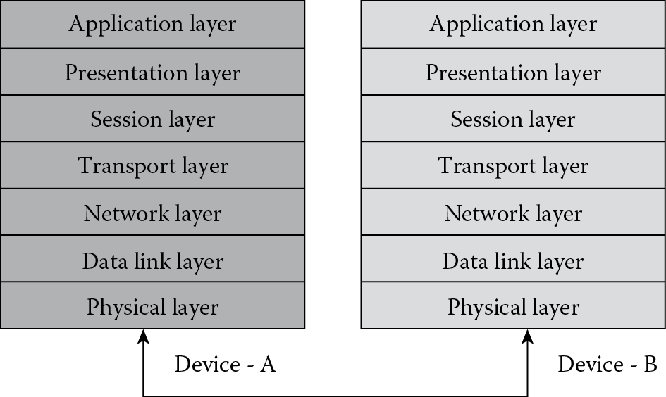
The lowest layer is referred to a layer 1 (L1) and moving up, the top most layer is layer 7 (L7). The physical layer is closest to the physical media for connecting two devices and hence is responsible for placing data in the physical medium. In most scenarios the physical layer is rarely a pure software component and is usually implemented as a combination of software and hardware. The application layer is closest to the end user and is mostly implemented as software. Communication involves transfer of data between devices. There are two key areas of focus here: the data and the device. Layers 7–4 deal with end to end communications between the “data” source and destinations. Layers 3–1 deal with communications between network “devices.” This chapter handles each of the layers in detail along with the protocols used to implement a specific layer. Network management protocols are usually application layer protocols but a basic understanding of the communication mechanism will help in understanding the different tasks involved in communication.
10.2 Physical Layer
This layer handles physical movement of data across the network interface. This layer is not just network cards and cables but defines a number of network functions. In the same way a network device like an Ethernet card is not just restricted to a physical layer but performs functions of both the physical and data link layer. Some of the physical can be of different types like open-wire circuits, twisted pair cables, coaxial cables, or fiber optic cables
Physical layer is the lowest layer in the OSI model concerned with data encoding, signaling, transmission, and reception over network devices.
Some of the functions of the physical layer are:
- Encoding: This would involve transformation of data in the form of bits with the device into signals for sending over a physical medium.
- Hardware specifications: Both the physical and data link layer together detail the operation of network interface cards and cables.
- Data transport between devices: The physical layer is responsible for transmission and reception of data.
- Network topology design: The topology and physical network design is handled by the physical layer. Some of the hardware related issues are caused due to missed configurations in the physical layer.
The encoding can result in conversion of data bits to signals of various schemas. Some of the signaling schemas that the physical layer can encode to are:
- Pulse signaling: Where the zero level represents “logic zero” and any other level can represent “logic one.” This signaling schema is also called “return to zero.”
- Level signaling: A predefined level of voltage or current can represent logic one and zero. There is no restriction that zero should be used to represent the logic zero. This schema is also called “non return to zero”
- Manchester encoding: In this schema “logic one” is represented by a transition in a particular direction in the center of each bit, where an example of transition can be a rising edge. Transition in the opposite direction is used to represent logic 0.
Physical layer also determines the utilization of media during data transmission based on signaling. When using “base band signaling” all available frequencies (the entire bandwidth) is used for data transmission. Ethernet mostly uses base band signaling. When working with “broadband signaling” only one frequency (part of the entire bandwidth) is used, with multiple signals transmitted simultaneously over the same media. The most popular example of broadband signaling is TV signals, where multiple channels working on different frequencies are transmitted simultaneously.
Physical layer also determines the topology of the network. The network can have bus, star, ring, or mesh topology and the implementation can be performed with LAN or WAN specifications. The physical layer should ensure efficient sharing of the communication media among multiple devices with proper flow control and collision resolution. Some examples of physical layer protocols are: CSMA/CD (carrier sense multiple access/collision detection), DSL (digital subscriber line) and RS-232. The physical layer is special compared to the other layers of the OSI model in having both hardware and software components that makeup this layer. There can be sublayers associated with the physical layer. These sublayers further break the functionality performed by the physical layer.
10.3 Data Link Layer
This is the second layer (L2) in the ISO/OSI model. It is divided into two sublayers, the logical link control (LLC) and media access control (MAC) on IEEE 802 local area networks, and some non-IEEE 802 networks such as FDDI. LLC is the upper sublayer and handles functions for control and establishment of connection for logical links between devices in the network. MAC is the lower sublayer in the data link layer (DLL) and handles functions that control access to the network media like cables.
The functions of the data link layer are:
- Frame Conversion: The final data for transmission is converted to frames in the data link layer. Frame is a fixed length piece of data where the length is dependent on hardware.
- Addressing: This involves labeling data with destination information based on hardware or a MAC address. This ensures that the data reaches the correct destination.
- Error detection and handling: Error occurring in the lower layers of the stack are detected and handled using algorithms like cyclic redundancy check (CRC) at the DLL.
- Flow control: Data flow control and acknowledgment in the data link as performed by the LLC sublayer.
- Access control: This is performed by the MAC sublayer and is required to ensure proper utilization of shared media.
The data link layer offers the following types of service to the higher layer:
- Unacknowledged connectionless service: In this type of service there is no logical connection established or released between the source and destination. It is mainly used in scenarios where the error rate and loss of frames is low. A popular example of using this form of service is in streaming audio and video.
- Acknowledged connectionless service: In this type of service there is no logical connection between source and destination, but an acknowledgment message is send by the receiver for each input message received from source. If no acknowledgment is received at the source the corresponding frame is assumed to be lost and the frame is re-sent.
- Acknowledged connection-oriented service: In this type of service there is a connection established between source and destination for data transfer and an acknowledgment is issued by the destination to notify the server that a particular packet was received. The frames are numbered. In this type of service, error and frame loss is minimal.
The elementary data link protocols for simplex unidirectional communication that form the basis to dictate flow control and development of DLL protocol are:
- Unrestricted simplex protocol: The receiver is assumed to have infinite capacity. Sender keeps on sending data to receiver as fast as it can.
- A simplex stop-and-wait protocol: The receiver only has a finite buffer capacity. Care should be taken to ensure that the sender does not flood the receiver.
- A simplex protocol for a noisy channel: The channel is noisy and unreliable hence care should be taken to handle frame loss, errors, and retransmission while implementing this protocol.
The best-known example of the DLL is Ethernet. Other examples of data link protocols are HDLC (high level data link control) and ADCCP (advanced data communication control protocol) for point-to-point or packet-switched networks and Aloha for local area networks.
10.4 Network Layer
This is the third lowest layer (L3) in the ISO/OSI model. While the data link layer deals with devices in a local area, the network layer deals with actually getting data from one computer to another even if it is on a remote network. That is, the network layer is responsible for source to destination packet delivery, while the data link layer is responsible for node to node frame delivery. Network layer achieves end to end delivery using logical addressing.
Addressing performed in data link layer is for the local physical device, while the logical address given in network layer must be unique across an entire internetwork. For a network like the Internet, the IP (Internet protocol) address is the logical address and every machine on the Internet needs to identify itself with a unique IP address.
The functionalities of the network layer are:
- Addressing: Every device in the network needs to identify itself with a unique address called the logical address that is assigned in the network layer.
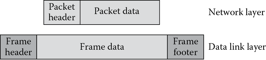
- Packetizing: The data to be communicated is converted to packets in the network layer and each packet has a network header (see Figure 10.2). The data to be packetized is provided by the higher layers in the OSI model. This activity is also referred to as datagram encapsulation. It can happen that the packet to be sent to the data link layer is bigger than what the DLL can handle, in which case the packets are fragmented at the source before it is sent to the DDL and at the destination the packets are reassembled.
- Routing: The software in the network layer is supposed to perform routing of packets. Incoming packets from several sources need to be analyzed and routed to proper destinations by the network layer.
- Error messaging: Some protocols for communication error handling resides in the network layer. They generate error messages about connection, route traffic, and health of devices in the network. A popular error handling protocol that is part of the IP suite that resides in the network layer is ICMP (Internet control message protocol).
Though the network layer protocol is usually connectionless, it can also be connection oriented. That is, the network layer protocol supports both connectionless and connection-oriented protocols. When connectionless protocol like IP is used in the network layer, data consistency and reliability are handled using connection-oriented protocols like TCP in the transport layer.
IP (Internet protocol) is the most popular network layer protocol. There are several other supporting protocols of IP for security, traffic control, error handling, and so on that reside in the network layer. These protocols include IPsec, IP NAT, and ICMP. Another network layer protocol outside the realm of the Internet protocol is IPX (inter-network packet exchange) and DDP (datagram delivery protocol).
10.5 Transport Layer
This is the fourth lowest layer (L4) in the ISO/OSI model. While the physical layer is concerned with transmission of bits, the data link layer with transmission in local area, and the network layer with transition even with remote systems, the transport layer handles transmission of data between processes/applications. There will be multiple applications running on the same system and there would be scenarios when more than one application from a specific source machine wants to send data to multiple applications on a destination machine. Transport layer ensures that multiple applications on the same system can communicate to another set of applications on a different system. This would mean that a new parameter in addition to the destination and source IP address is required for application level communication.
So a transport protocol can have simultaneous connections to a computer and ensure that the receiving computer still knows what application should handle each data packet that is received. This task is accomplished using “ports.” The parameter port is just an internal address that facilitates control of data flow. Ports that have specific purposes and used for generic applications across systems are known as well-known ports. For example data is routed through well-known TCP port 80 while using the Internet. While an IP address can be used to route data to a specific network element and the port number to direct data to a specific application, both of these tasks can be jointly done by an identifier called the socket. A socket is an identifier that binds a specific port to an IP address.
Transport layer supports both connection-oriented protocol and connectionless protocol. Connection-oriented protocol is the more common for reliable data communication as a connection needs to be established before data transfer. It allows for error checking functionality and stability. Connectionless protocol does not require a reliable connection established between the application during the entire duration of data transfer and it lacks extensive error checking. Connectionless protocol is considered to be much faster than connection-oriented protocol and is mainly used in intermittent communication.
The functions of the transport layer are:
- Connection management: In case of a connection-oriented protocol the transport layer ensures establishing the connection, maintaining the connection during data transfer and termination of connection after the transfer is complete.
- Congestion avoidance and flow control: There can be a scenario when the sender transmits data at a rate higher than the value that the receiver can handle. This scenario of flooding the receiver is called congestion. Regulating the flow of data or flow control can avoid congestion. Transport layer can implement flow control.
- Reliable data transfer: Acknowledgments can be used by the receiver to inform the sender about safe delivery or loss of data. Retransmission of lost data can also be implemented in the transport layer.
- Process level communication using ports and sockets.
- Data processing: Data segments from different processes can be combined to a single stream at the sender and again fragmented at the receiver. Also a large bulk of data can be split into segments at the sender and then combined again at the receiver.
The TCP (transport control protocol) and UDP (user datagram protocol) are the most popular transport layer protocols. TCP sends data as packets while UDP sends data as datagrams. TCP is connection oriented and UDP is connectionless. Connection-oriented services can be handled at the network layer itself, though it is commonly implemented at the transport layer.
10.6 Session Layer
This is the fifth lowest layer (L5) in the ISO/OSI model. All the functionality of identifying the destination and application to communicate is done in the layers lower to the session layer. So addressing and data processing is not done in the session layer. As the name suggests, session layer is mainly intended for session management, which includes establishing, maintaining, and terminating a session. Session is a logical linking of software application processes, to allow them to exchange data. A session is usually established between applications to transfer a file, send log-on information and for any type of data transfer.
Session can be of two types:
- Half duplex: In half duplex only one way communication is permitted at any point of time. So when a session is established between two network elements, each element has to communicate in turn as only one element is permitted to send data in half duplex mode.
- Full duplex: In full duplex session, both the network elements that have established a session for interaction can communicate or send data at the same time.
Some of the popular session layer protocols are session initiation protocol (SIP) and AppleTalk session protocol (ASP). Session layer software in most scenarios is more of a set of tools rather than a specific protocol. For instance RPC (remote procedure call) usually associated with the session layer for communication between remote systems gives more of a set of APIs (application program interfaces) for working on remote sessions and SSH (secure shell), another protocol associated with session layer also gives the implemented the ability to establish secure sessions. While the term session is usually used for communication over a short duration between elements, the term connection is used for communication that takes place for longer durations.
Let us consider a typical scenario of how a session layer works when handling a single application. The Web page displayed by a Web browser can contain embedded objects of media, text, and graphics. This graphic file, media file, and text content file are all separate files on the Web server. If the browser is a pure application object that cannot handle multiple objects together then a separate download must be started to access these objects. So the Web browser opens a separate session to the Web server to download each of these individual files of the embedded objects in the Web page. The session layer performs the function of keeping track of what packets and data belong to what file. This is required so that the Web page can be displayed correctly by the Web browser.
10.7 Presentation Layer
This is the sixth lowest layer (L6) in the ISO/OSI model. The role of the presentation layer is to ensure that communication between applications in two different systems occur even when the data representation format is not the same. As the name suggests, a common syntax or format that the two interacting systems can understand is presented to the systems at the presentation layer. The conversion of application specific system to presentation system happens both in the transmitting system and the receiving system. This common presentation syntax is called transfer syntax.
There can be abstract forms to define data types called abstract data syntax and presentation forms for transfer and presentation of data called transfer syntax. In order to ensure that common syntax definitions are available for data recognition, ISO defined a general abstract syntax for the definition of data types associated with distributed applications. This abstract syntax is known as abstract syntax notation number one or ASN.1. The data types associated with ASN.1 are abstract data types. Along similar lines, transfer syntax was defined by OSI for use with ASN.1. This transfer syntax notation developed by OSI is known as basic encoding rules (BER).
The functions performed by the presentation layer are:
- Translation for representing data in a common format: A network will be comprised of machines running on different OS like Windows, UNIX, Macintosh, and so on. These machines differ in characteristics of data presentation. The presentation layer handles translation of data to a known format, thus hiding the differences between machines. This translation includes data transformation, formatting, and special purpose transformations.
- Request for session establishment, data transfer, and termination: Though session management is handled by the session layer, the request to perform session-related operations like the request for establishment of a session, the data transfer, and the final termination originates from the presentation layer.
- Negotiation of syntax: The presentation layer does the job of negation of syntax for data transfer. Multiple negotiations are performed before a common format/syntax is agreed upon between systems that want to communicate.
- Compression and decompression: This function is not usually performed in the presentation layer, but to improve the throughput of data, compression and decompression can be performed in this layer. Some functions, like compression to increase throughput and encryption to increase security, can be performed in almost any layer of the OSI model.
- Encryption of data: Implementing security for the data that travels down the protocol stack is a key functionality of the presentation layer. Encryption is performed on the data at the presentation layer and it can also be performed at the layers below the presentation layer. One of the most popular encryption schema associated with the presentation layer is the secure sockets layer (SSL) protocol.
The presentation layer is not always used in network communication. This is because most of its functionalities are optional. The encryption and compression can be formed at other layers in the OSI model. For data translation to come up with a common format is only required when handling heterogeneous systems. The remaining functions of the presentation layer can be performed by the application layer. Most of the protocol stack implementations may not have a presentation layer.
There are three syntactic versions that are important when two applications interact:
- Syntax of the application entity that requested the connection.
- Syntax of the application entity that receives the connection.
- Syntax used by the presentation entities in giving a common format.
The syntax of the application entity at the transmitting or requesting end is converted to syntax used by the presentation entity at the presentation layer of a requesting system. In the same way, the syntax used by the presentation entity is converted to the syntax used by an application entity at the receiving end at the presentation layer of the receiving system.
Another example of a presentation layer protocol is XDR (external data representation). XDR is used as the common data format mostly when interaction is involved with a system running UNIX OS. For a UNIX system to interact with a heterogeneous system running another OS, using remote procedure calls (RPC), the usual presentation layer format is XDR. XDR has its own set of data types and the application layer types will get converted to XDR format before transfer of data and the response data also needs to be converted to XDR. In a distributed system having heterogeneous systems, the presentation layer plays a key role to facilitate communication.
10.8 Application Layer
This is the top most layer of the OSI model. Being the seventh lowest layer in the ISO/OSI model it is also referred to as L7. The application layer manages communication between applications and handles issues like network transparency and resource allocation. In addition to providing network access as the key functionality, the application layer also offers services for user applications.
Let us consider how the application layer offers services for user applications with an example of World Wide Web (www). The Web browser is an application that runs on a machine to display Web pages and it makes use of the services offered by a protocol that operates at the application layer. Viewing the vast collection of hypertext-based files available on the Internet as well as providing quick and easy retrieval of these files using a browser is made possible using the application layer protocol called hyper text transfer protocol (HTTP).
Some of the other popular application layer protocols include simple mail transfer protocol (SMTP) that gives electronic mail functionality to be implemented in applications through which all kinds of data can be sent to other users of the Internet as an electronic postal system and file transfer protocol (FTP) is used to transfer files between two machines. The network management protocol SNMP is also an application layer protocol as it provides interfaces for network management applications to collect network data.
A program that implements the interfaces provided by the application layer protocol is required in the machine. That is, an FTP client should be running on the machine to transfer files from the FTP server and an SNMP agent should be running on the network element to source data to a network manager using the SNMP protocol.
The user application can operate without an application layer using protocol modules that initialize communication with other application, set up the presentation context, and transfer messages. In this mode of operation the application will interact directly with the presentation layer. In the same manner the application can implement modules that perform the application services offered by the application layer. These modules are called application specific elements.
Application layer protocols are classified into:
- Common application specific elements (CASE)
- Specific application specific elements (SASE)
As the name signifies, CASE elements are the integrated set of functions that are commonly used by an application while SASE elements are written on a need basis for a specific functionality. Some of the CASE related functions include initialization and termination of connection with other processes, transfer of message with other processes, or underlying protocol and recovering from a failure while a task is under execution.
It should be understood that not all applications use the application layer for communication and applications are not the only users of the application layer. The operating system (OS) itself can use the services directly from the application layer.
10.9 TCP/IP Model and OSI Model
The OSI model is the not the only network model available for implementing protocol stacks for communication between network elements. The four layer TCP/IP model was developed before the OSI model and is also one of the most popular models for implementing protocol stack (see Figure 10.3). The functions performed by the four layers in the TCP/IP model can be mapped to the functions performed by the seven layers of an OSI model.

The layers in the TCP/IP Model are:
- Application layer: This is the top most layer of the TCP/IP model and performs functions done by application, presentation, and session layer in the OSI model. In addition to all the processes that involve user interaction, the application also controls the session and presentation of data when required. The terms like socket and port that are associated with the session layer in an OSI model are used to describe the path over which applications communicate in TCP/IP model. Some of the protocols in this layer are FTP, HTTP, SMTP, and SNMP.
- Transport layer: This layer of TCP/IP model performs functions similar to the transport layer of an OSI model. There are two important transport layer protocols, the transmission control protocol (TCP) and user datagram protocol (UDP). While TCP guarantees that information is received as it is a connection-oriented protocol, the UDP works on a connectionless setup suitable for intermittent networks and performs no end-to-end reliability checks. Flow control is also performed at this layer to ensure that a fast sender will not swamp the receiver with message packets.
- Internet layer: This layer of the TCP/IP model performs functions similar to the network layer of an OSI model. The Internet layer is suited for packet switching networks and is mostly a connectionless layer that allows hosts to insert packets into any network and delivers these packets independently to the destination. The work of the Internet layer is limited to delivery of packets and the higher layers perform the function to rearrange the packets in order to deliver them to the proper application in the destination. The Internet protocol defines the packet format for the Internet layer. Routing of packets to avoid congestion is also handled in the Internet layer. This is a key layer of the TCP/IP model and all data has to pass this layer before being sent to lower layers for transmission.
- Network interface layer: The physical layer and data link layer of the OSI model are grouped into a single layer called network interface layer in the TCP/IP model. This layer is used by the TCP/IP protocols running at the upper layers to interface with the local network. The TCP/IP model does not give much detail on the implementation or the specific set of functions to be performed at the network interface layer except it being the point for connection of host to network and use of an associated protocol to transmit IP packets. Protocols like point-to-point protocol (PPP) and serial line Internet protocol (SLIP) can be considered protocols of the network interface layer. The actual protocol used in the network interface layer varies from host to host and network to network. The network interface layer is also called the network access layer. In some implementations of the network interface layer, it performs functions like frame synchronization, control of errors, and media access.
There are some significant differences between the OSI model and TCP/IP model.
- In the TCP/IP model, reliability is mainly handled at the transport layer. The transport layer takes on all functions for handling data transfer reliability, which includes capabilities like error detection and recovery, checksums, acknowledgments, and timeouts.
- The other difference is the presence of intelligent hosts when using a TCP/IP model. This means that an OSI model does not handle management of network operations while most TCP/IP implementations like Internet have capabilities to manage network operations, which make them intelligent hosts.
- OSI model was developed as a standard and serves more as a teaching aid. This is because it clearly demarcates the functionality to the performed when two systems interact over a distributed environment. On the other hand, the TCP/IP model was adopted as a standard due to more widespread application of the model in domains like the Internet. It should be noted that the TCP/IP model was developed before the OSI model.
10.10 Conclusion
The network model is required to have a good understanding of how two network elements communicate whether the elements are in the same network or in two separate networks. The OSI model is the most common model used in text book descriptions to give the reader an understanding of the functionalities in an interaction between elements spit into a set of layers while the TCP/IP is the most popular model for implementing protocol stacks of interaction. It can be seen that TCP/IP is a type of OSI model where a single layer performs multiple layer functions. From a functional model perspective, both the TCP/IP model and OSI model are the same.
Additional Reading
1. Debbra Wetteroth. OSI Reference Model for Telecommunications. New York: McGraw-Hill, 2001.
2. Uyless D. Black. OSI: A Model for Computer Communications Standards. Facsimile ed. Upper Saddle River, NJ: Prentice Hall, 1990.
3. American National Standards Institute (ANSI). ISO/IEC 10731:1994, Information Technology: Open Systems Interconnection: Basic Reference Model: Conventions for the Definition of OSI Services. ISO/IEC JTC 1, 2007.
4. Charles Kozierok. The TCP/IP Guide: A Comprehensive, Illustrated Internet Protocols Reference. San Francisco, CA: No Starch Press, 2005.