Chapter 1
What Is EMS?
This chapter is intended to provide the reader with a basic understanding of Element Management System. At the end of this chapter you will have a good understanding of what is a network element, the need for managing a network element, how an element management system fits into telecom architecture, and some of the major vendors involved in the development of EMS.
1.1 Introduction
Industries are highly dependent on their networking services for day-to-day activities from sending mail to conducting an audio/video conference. Keeping services running on the resource is synonymous with keeping the business running. Any service is offered by a process or set of processes running on some hardware. A set of hardware makes up the inventory required for keeping a service up and running. If the hardware goes down or when there is some malfunction with the hardware, this would in turn affect the service. This leads to the need to monitor the hardware and ensure its proper functioning in order to offer a service to a customer. This hardware being discussed is the element and an application to monitor the same constitutes the element management system. Since the element is part of a network, it is usually referred to as network element or NE.
A network element is the hardware on which a process or set of processes is executed to offer a service or plurality of services to the customer.
EMS is an application that manages a telecom network element.
Most element management systems are available in the market support management data collection from multiple network elements though they cannot be called a network management system. Hence an application is not necessarily a network management system just because it supports data collection from multiple NEs. The functionalities offered by the systems decide whether it is a network management system (NMS) or an element management system (EMS). Let us make this point clear with an example. A topology diagram in an EMS would have the nodes configured in the element while a topology diagram in an NMS will show all the configured network elements managed by the NMS. Again a fault management window on an EMS would show only the logs and alarms generated on the network element it is managing. The functionalities like fault correlation and decision handling based on events from various NEs are shown in an NMS.
The functionalities of an EMS are covered in detail in the chapters to follow. This introduction is intended to only give the reader a feel of what a network element and EMS is in telecom domain. In the sections to follow we will explore the architecture of EMS and take some sample EMS products to gain familiarity with EMS applications available in the market.
1.2 EMS in Telecom
As shown in Figure 1.1, an element manager (EM) collects data from the network elements (NE). An ideal scenario would involve one element manager to collect data from a single network element as in EM-2 and NE-n. It can be seen that this is not the case for an actual EMS product. Almost all the EMS products available in the market support management of a set of elements as shown for element managers other than EM-2 in Figure 1.1.
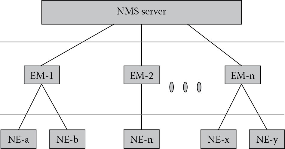
Even when data is collected from multiple NEs, the management system is still an element manager when data collection and processing is handled on a per NE basis and functionalities offered by the EM does not include any function that represents processed output from an aggregate of data collected from different NEs.
It is seen that while enhancing an EMS product or to make the product competitive in the market, many EMS solution developers offer some of the NMS related functionalities that involve processing of collected data from multiple NEs to display network representation of data. This point needs to be carefully noted by the reader to avoid getting confused when handling an actual EMS product that might include some NMS features as part of the product suite.
Figure 1.1 showing layered views closely resembles the TMN model with the network elements in the lowest layer, above which is the element management layer followed by network management layer. The TMN model is handled in much detail in Chapter 2.
The NMS server may not be the only feed that collects data from an EMS server. The EMS architecture is handled in more detail in the next section where the various feeds from an EMS sever are depicted pictorially and explained.
1.3 EMS Architecture
The element management system in Figure 1.2 is the EMS server that provides FCAPS functionality. The FCAPS is short for Fault, Configuration, Accounting, Performance, and Security. Basic FCAPS functionality at element level is offered in EMS layer. The FCAPS is also referred in conjunction with the NMS layer as an enhanced version of these functionalities come up in the NMS layer. While EMS looks at fault data from a single element perspective, an NMS processes an aggregate of fault data from various NEs and performs operations using this data.
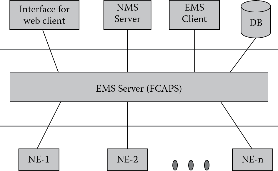
Data collected by the EMS from the network elements are utilized by:
- NMS Server: The NMS uses collected as well as processed data from the EMS to consolidate and provide useful information and functionalities at a network management level.
- EMS Client: If data from EMS needs to be represented in GUI or as console output to a user then an EMS client is usually implemented for the same. The EMS client would provide help in representing the data in a user-friendly manner. One of the functions in ‘F “C” APS’ is configuring the network elements. The EMS client can be used to give a user-friendly interface for configuring the elements.
- Database (DB): Historical data is a key component in element management. It could be used to study event/fault scenarios, evaluate performance of the network elements, and so on. Relevant data collected by EMS needs to be stored in a database.
- Interface for web client: Rather than an EMS client, most users prefer a lightweight, web-based interface to be a replacement for the web client. This functionality is supported by most EMS solutions.
- The EMS output could also be feed to other vendor applications. These external applications might work on part or whole of the data from the EMS.
1.4 Need for EMS
The complexity of new services and the underlying network is increasing exponentially. At the same time there is a lot of competition among service providers offering new and compelling services. This leads to the need for minimizing the cost of network operations. This can only be achieved if the elements in the network are well managed. The increase in complexity can be handled cost effectively only by providing good user interface for managing the service and network thus hiding complexity. The other option of having more trained professionals is both expensive and risky.
Let us try to list the major issues in telecom industry that necessitates the need for a user-friendly and functionality-rich EMS:
- There are an increasing variety of NEs: New network elements are being developed to provide new services. In the network itself there are multiple telecom networks like GSM, GPRS, CDMA, IMS, and so on with independent work being carried out in the development of access and core network.
- Need to support elements from different vendors: Mergers and acquisitions are inevitable in the telecom industry. So a single EMS product might be required to collect data from a family of network elements.
- Increase in complexity of managing NEs: With advances in telecom industry there is a major trend to combine functionalities performed by multiple elements to a single element. For example, most vendors now have a single SGSN performing functionality of U-SGSN and G-SGSN and a media gateway is embedded with functionality to handle signaling protocols.
- Shortage of trained telecommunications technicians: Telecom industry is evolving so rapidly that telecom technicians are not able to keep pace with the same. This leads to a shortage of trained professionals in maintaining the network. With a functionality rich and user-friendly EMS solution, the effort to train technicians is reduced.
- Need to reduce cost of managing network and high-quality innovative services: Cost of managing the network and service is one major area where companies want to cut down cost as they do not directly generate revenue, unlike customer management and research activities that could help to get and retain business.
Meeting these challenges requires element management systems (not just EMS but good NMS, OSS, and BSS also) with the maximum efficiency and flexibility with respect to accomplishing tasks.
1.5 Characteristics Required in EMS
The characteristics required in an EMS solution are:
- User-friendly interface: The interface to work with the EMS (EMS client or web client) needs to be an intuitive, task-oriented GUI to allow operations functions to be performed in the shortest possible time with minimal training.
- Quick launch: This would enable a user working at the NML, SML, or BML to launch any EMS desired (when multiple EMS are involved).
- Troubleshoot NE: It should be possible for a technician to directly log into any NE from the EMS that manages it for ease in troubleshooting an issue. Single-sign-on is a popular capability that allows the same user id and password to be used when logging into the applications involved in different layers of TMN model that will be discussed in the next chapter.
- Low-cost operations platform: This would help in minimizing the total cost to own and operate the computing platform on which the EMS runs.
- Ease of enhancement: New features need to be added to an EMS product and the product might require easy integration and work with another product. Some of the techniques currently adopted in the design of such systems is to make it based on service oriented architecture (SOA), comply to COTS software standards, and so on.
- Context-sensitive help: This reduces the training required for technicians. Context-sensitive help can be associated with any functionality in EMS GUI. With event/fault, a context-sensitive help would involve a quick launch link for information on that fault. Another usual feature in applications is a “?” icon that can be dragged and dropped to any part of the application and a help is launched on how to work on the specific part where the icon is dropped.
- Access anywhere: This would require a person in any remote location to access the EMS. As already discussed most EMS now provide a web-based interface so that with secure connection technique the internet can be used to access company intranet and launch the web-based EMS.
- Effective database: All possible data collected from NE needs to be stored into the EMS database. This will improve service, save time, and save money. There should also be a functionality to generate standard reports and the ability to export data to other application tools that specialize in analysis and reporting.
Above all, the key to being a leader in EMS development is to make the product functionality rich and to ensure that there are key features that differentiate the product from its competitors.
1.6 Popular EMS Products
The data sheet below is a list of popular EMS products available in the market. Some or most of the product has capabilities that span outside the element management layer and might involve some level of network and service management. The information is compiled from data in the World Wide Web and does not present the authors opinion about a specific product. The products are listed in alphabetical order (see Table 1.1).
Some other EMS products from popular network equipment manufacturers are:
- Nortel’s Integrated Element Management System
- Aveon Element Management Software
- Fujitsu’s NETSMART Element Management System
- LineView Element Management System from Alcatel-Lucent
- NMC-RX EMS from Juniper Networks
1.7 Conclusion
This chapter thus provides a basic understanding of an element management system (EMS) and what a network element is from the perspective of EMS. The chapter also helps to understand the role of EMS in the telecom layered view and the EMS architecture. The need for element management systems and the characteristics of an ideal EMS is covered. To give the reader familiarity with the EMS products and functionalities, a data sheet is also provided that shows some of the leading EMS products and their features. The information provided in the data sheet can be obtained from the company Web site that will give more information on the products.
Additional Reading
1. Vinayshil Gautam. Understanding Telecom Management. New Delhi: Concept Publishing Company, 2004.
2. James Harry Green. The Irwin Handbook of Telecommunications Management. New York: McGraw-Hill, 2001.
3. Kundan Misra. OSS for Telecom Networks: An Introduction to Network Management. New York: Springer, 2004.